201 Approach to Optimize Energy Efficiency
Waste Incineration
Approach to Optimize Energy Efficiency
Frédéric Aguesse, Maud Tacci and Damien Lebonnois
1. New energy from waste plants ...202
1.1. Combination of electricity and steam export ...202
1.2. Steam supply to an industrial park produced by wood waste ...203
1.3. Flue gas recirculation ...203
2. Existing energy from waste plants ...207
2.1. Low temperature heat export ...207
2.2. Supply of steam to greenhouse ...208
2.3. Back pressure turbine installation to supply steam to an industrial client ...208
2.4. Use of waste heat and bleeding to supply a district heating or greenhouses, using thermocompressor ...208
2.5. Organic Rankine Cycle (ORC) ...210
2.6. Optimization of boiler efficiency ...211
3. Conclusion ...211
Suez is a worldwide company, present on all five continents. Water and waste manage- ment are the main activities of the group and both are involved in optimizing energy efficiency. However, this paper will focus on Waste activity and more precisely on the energy from waste (EfW) activity.
Suez operates more than fifty EfW plants mainly in Europe but also in Asia. The dif- ferent plants are reported on Figure 1. The size of the plot is proportional to the size of the plant.
R&R UK R&R Asia R&R News R&V France R&R Polska
Figure 1:
Map of worldwide energy from waste plants operated by Suez
Frédéric Aguesse, Maud Tacci, Damien Lebonnois
202
Waste Incineration
An optimized energy efficiency has always been at the center of the operational excellence developed by the French corporation. Recently, this trend has even been reinforced, driven in particular by an increased competition on the waste treatment market and lower electricity selling prices (Figure 2). Tax incentives for higher energy efficiency have also appeared to favor investment on existing plants, for example in France (incineration tax lowered in case of high efficiency).
Spot Electricity Prices EUR/MWh
60 50 40 30 20 10 0
2011 2012 2013 2014 2015 2016
Figure 2:
Spot electricity prices in the last years
This paper reports some of the French operator‘s main achievements in terms of op- timized energy efficiency on EfW plants, both on new and existing plants, through optimized and innovative solutions.
1. New energy from waste plants
1.1. Combination of electricity and steam export
For some years now, the new EfW plants have been designed and built according to a need in steam and/or heat export.
An example is the Wilton plant developed for the Merseyside County (UK). This plant is a way to:
• move up the waste hierarchy and replace landfill,
• reduce greenhouse gas emissions created by landfill and to substitute fossil fuel (CO2 mitigation, around 127.3 kt per year),
• produce and supply electricity and steam,
• offer a long term stability in the steam price thanks to the permanent operation (except the maintenance stop) of the turbine and EfW in general.
To achieve those targets, a set of technologies have been proposed and carried out. The turbine is a 50 MWe electricity production with steam bleeding properly designed to supply an Industrial park. Three pressure stages are supplied all year round:
• high pressure (60 bara), 1.5 MW supplied and 12 GWh per year,
203 Approach to Optimize Energy Efficiency
Waste Incineration
• intermediate pressure (20 bara), 33 MW supplied and 261 GWh per year,
• low pressure (2.3 bara), 8 MW supplied and 62 GWh per year.
Steam export represents 335 GWh per year in total, the Industrial clients supply de- mineralised water in return of the exported steam. Electricity production represents 260 GWh per year. The condenser system is a hybrid one, which combines a water cooled condenser and a cooling tower, to optimize the vacuum/electricity efficiency and lower the water consumption.
1.2. Steam supply to an industrial park produced by wood waste
Another example is the Robin unit, located close to Lyon in France. All the steam produced is supplied to the Osiris platform, a chemical platform of sixteen companies on a 150 ha area.
The unit consists of a 21 MWth vertical fluidized bed boiler with automatic chip wood/waste wood feeding. The steam production is from 25 to 31 t/h at 32 bara and 270 °C. This leads to an 18.7 MW export and around 153 GWh per year with an 8,200 h availability. The heat loss is pretty low (around 11 percent) as all the steam produced is consumed. This fact is well illustrated by the Sankey diagram on Figure 3.
Biomass input 100 %
Total
entrance: 105 %
Furnace and Boiler losses: 11 %
Air heater: 5 %
Steam supply: 89 %
Figure 3:
Robin Sankey diagram
The steam sold represents 14 percent of Osiris needs. The project has been sponsored by the French Environment and Energy Management Agency (ADEME) to promote the use of Biomass heat for Industry, agriculture and service sector (BCIAT). It helps mitigate CO2 emissions, with 56,000 t CO2 per year being avoided.
1.3. Flue gas recirculation
1Flue gas recirculation (FGR) has been implemented on several recent Suez EfW Plants and is an efficient solution when the following criteria have to be respected:
• low oxygen at the boiler outlet,
• low raw NOx required,
1 based on Hitachi Zosen Inova client event presentation 2016
Frédéric Aguesse, Maud Tacci, Damien Lebonnois
204
Waste Incineration
• strong cooling downstream recirculation branch,
• complex flue gas treatment downstream recirculation branch,
• specific conservative combustion requirements (such as adiabatic temperature limits, waste with slagging properties),
• size of the Plant: possibility to reduce the sizing of the equipment downstream the recirculation branch.
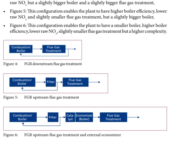
Different configurations can be carried out depending of the needs, as shown on Figures 4, 5 and 6. This list of different configurations is not exhaustive:
• Figure 4: This configuration enables the plant to have higher boiler efficiency, lower raw NOx but a slightly bigger boiler and a slightly bigger flue gas treatment,
• Figure 5: This configuration enables the plant to have higher boiler efficiency, lower raw NOx and slightly smaller flue gas treatment, but a slightly bigger boiler,
• Figure 6: This configuration enables the plant to have a smaller boiler, higher boiler efficiency, lower raw NOx, slightly smaller flue gas treatment but a higher complexity.
Combustion/
Boiler Flue Gas
Treatment
Figure 4: FGR downstream flue gas treatment
Combustion/
Boiler Flue Gas
Treatment Filter
Figure 5: FGR upstream flue gas treatment
Combustion/
Boiler Flue Gas
Treatment
Filter Economizer
(Boiler) Cata-
lyst
Figure 6: FGR upstream flue gas treatment and external economizer
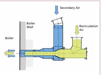
However, common issues have been noticed, here are the appropriate mitigations:
• corrosion in recirculation system
* check sufficient insulation and good quality in assembly (Figure 7),
• blockages of injection nozzles
* ensure sufficient dust reduction before recirculation,
* adequate cleaning possible during operation.
BORSIG Service GmbH
Egellsstraße 21, 13507 Berlin Tel.: 030 / 4301-01
Fax: 030 / 4301-2771 E-mail: info@bs.borsig.de
www.borsig.de/bs
Power Plant Services
BORSIG Service GmbH, Berlin, offers comprehensive services for the power engineering, chemical and petrochemical industries as well as oil, gas and water supply. With more than 160 years of experience in the construction of steam generators, we offer the competence necessary for full-scale services in the field of energy and steam generation plants and systems.
Our services in detail:
- Repair, maintenance and modification work - Ongoing maintenance
- Installation and dismantling
- Co-ordination of external contractors
- Performing measurements, analyses and acceptance procedures
- Supply of spare parts and replacement components according to third-party drawings or our own design
- Design of boiler modifications and retrofits with 2D and 3D CAD - Overseeing boiler and power plant technology investment projects - 24-hour standby service
- And NEW: our so-called „BLITZMOBIL“ - a fully equiped mobile workshop emergency van
Competent, quick and near to the customer - our efficient service and installation team makes this claim reality.
CNIM
35, rue de Bassano, 75008 Paris - France
Tel.: + 33 (0)1 44 31 11 00 - Fax: + 33 (0)1 44 31 11 30 E-mail: contact@cnim.com
www.cnim.com
Waste is a renewable energy source
> Turnkey design & build and services
> For:
• Household waste
• Commercial and industrial waste
• Biomass
• Fuels derived from waste
> To produce:
• Recyclable materials
• Compost
• Energy (heat and electricity)
Ardley Energy-from-Waste plant, Oxfordshire, UK
Courtesy of Viridor - © Julien Goldstein 08/2017 - Agence Huitième Jour
207 Approach to Optimize Energy Efficiency
Waste Incineration
2. Existing energy from waste plants
Most of the oldest existing EfW plants were designed and built to supply electricity only. With the current context, supplying heat and/or steam with the lowest investment cost becomes an important stake.
Boiler
Boiler Wall
Secondary Air
Recirculation Air
Figure 7:
Configuration of secondary air and recirculated flue gas nozzles
2.1. Low temperature heat export
ReEnergy plant, localized in Roosendaal (Netherlands), is now supplying heat to a recently developed low temperature district heating. The exported steam is taken at the exit of the turbine, which has no impact on electricity production. On the contrary it increases the electricity sold to the network, as less steam flow goes to the Air Cooled Condenser, which reduces the plant electricity consumpti- on. The operating temperature is 40 °C, directly used for building heating and upgraded to sanitary conditions (greater than 65 °C) by heat pump. This is a small district heating (5 MWth and around 25 GWh per year), but it enables a CO2 reduction of 50 percent for users. The installation has been operated for a few years now and is being further developed by the City.
Figure 8: Heat exchanger installed on site, ReEnergy
Frédéric Aguesse, Maud Tacci, Damien Lebonnois
208
Waste Incineration
2.2. Supply of steam to greenhouse
Within Suez, two plants are now supplying low temperature fatal heat to recently developed greenhouse projects:
• One in Econotre plant, localized in France. Waste-heat is used to supply a 10 ha Greenhouse at 50 °C. It represents around 5.5 MWth and 30 GWh per year. The heat supplied has a low cost for the users as it is waste-heat and does not impact the electricity production.
• One in ReEnergy plant, localized in the Netherlands. They use a turbine bleed as the temperature needed is 90 °C. It represents around 7.9 MWth and 42 GWh per year.
To optimize the plant energy production and to supply heat even during unplanned stops, a heat buffer has been installed.
Those two greenhouse projects are both currently in operation. They are two good examples of increased environmental synergy with external partners and local accep- tance regarding the plant image. In addition, greenhouse projects are a way to develop employment, with up to seven people per hectare.
Figure 9:
Greenhouse close by econotre plant
2.3. Back pressure turbine installation to supply steam to an industrial client
The industrial client Tereos (sugar producer), close to Le Havre (France), needed superheated steam from 16.8 to 18.6 bara. It was decided to replace the existing con- densation turbine by a back pressure one, designed to be able to supply the desired steam to the industrial client. This enables the plant to supply a large amount of steam (16 MWth up to 41 MWth equivalent to 290 GWh per year) while still producing electricity (3.9 MWe turbine). This green energy supply covers up to 70 percent of Tereos needs.
On this project, it was possible to use this technology (back-pressure turbine) because of stable needs in steam characteristics all year round. Those conditions are also key to maintain a fixed price (not depending on fossil fuel prices) for steam supply all year round.
2.4. Use of waste heat and bleeding to supply a district heating or greenhouses, using thermocompressor
EfW facilities convert 20 to 30 percent of the energy throughput into electricity. About 50 percent of the energy throughput is heat lost at the condenser (Figure 10). The avail- able temperature of this heat is low (40 to 60 °C, depending on external temperature).
209 Approach to Optimize Energy Efficiency
Waste Incineration
Figure 10: Sankey Diagram of conventional EfW
The thermo-compression technology (Suez International Patent, PCT/IB2012/057419, 12/18/2012 – demonstrating Suez commitment to improving Energy efficiency) enables to supply users with higher temperature, minimizing the electricity loss. This technology is suitable for small heat flow export or variable heat export (in power and/or pressure/
temperature) during the year, otherwise back pressure turbine will be promoted.
25 % Electricity production
25 % Heat lost in the process 50 % Waste heat at the condenser
a part of this low T °C heat can be recovered 75 % Turbine
Waste energy thoughput
100 %
Motive Steam Steam at the tubine
Venturi Head chamber
Ejector Discharge Steam To exchanger
Suction steam Exhaust steam of the turbine
Figure 11: Thermo-compressor
CHP + TC Process
Hot water supply 58 °C Turbine
Thermo-compressor Water cooled condensed
Exchanger Water/Water Condensates
42 °C
58 °C 48 °C Condensates
45 °C Condensates 45 °C
50 °C, 125 mbar Exhaust steam
60 °C, 200 mbar
MP steam bleed 160 °C, 5 bar
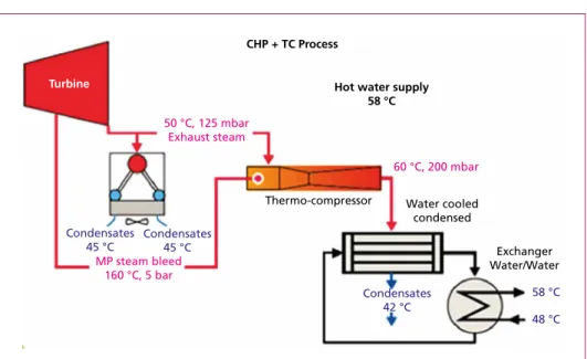
Figure 12: Example of thermo-compressor use
Frédéric Aguesse, Maud Tacci, Damien Lebonnois
210
Waste Incineration
A motive steam (mostly turbine bleeding) is used to elevate exhaust steam (also called suction steam) temperature and pressure (according to users’ needs). The lowest the needed temperature is, the lowest will be the motive steam consumption and therefore the electricity loss. The air-cooled condenser electricity consumption is also lower thanks to the use of turbine exhaust steam. An example is shown on Figure 12.
The utilizations can be:
• to dry biomass, manure, algae and others... ,
• hot water for industries, residential areas, hospitals and swimming pools,
• aquaculture basins,
• others.
The low capital expenditure (CapEx) involved and mostly waste-heat uses enable to sell the heat at a cost effective price, which is very attractive for the local users.
2.5. Organic Rankine Cycle (ORC)
Another example of increased energy efficiency for EfW plants is the use of an Organic- Rankine-Cycle (ORC) to produce electricity from low or medium temperature waste heat. An example of available medium temperature heat is given by the plants designed to supply only heat to a heating district network, where seasonal load variations occur, resulting in a lower energy efficiency (in terms of used energy) during summer time.
To increase the energy efficiency during the low heat-consumption periods, an ORC unit was installed on the SIRAC EfW plant (near Caen, France), using the superhea- ted water (190 °C) as a heat source to produce electricity (2 MWe). In addition to the electricity production, some low temperature heat is recovered from the organic fluid to supply heat to nearby greenhouses.
This ORC unit was supplied by Enertime and is currently under commissioning.
Figure 13:
2 MWe ORC turbine installed in SIRAC EfW plant
211 Approach to Optimize Energy Efficiency
Waste Incineration
2.6. Optimization of boiler efficiency
As part of the continuous search for operational excellence in the Suez EfW plants, optimization of the boiler efficiency was identified as a key parameter.
Having long-term experience about EfW operation with several boiler suppliers, Suez has been able to collect and consolidate REX on all cleaning systems usually available on EfW boilers: soot blower, water cannon, acoustic vibration, rapping, chemical cleaning, water shower, explosion cleaning, shot cleaning. Those REX are key to optimize the cleaning strategy and thus the boiler efficiency.
In addition to that return on experience, the French operator is also able to implement custom-made boiler fouling indicators in order to monitor accurately the boiler fou- ling conditions, leading as well to an optimized cleaning strategy and boiler efficiency together with reduced unplanned stops and operating costs.
3. Conclusion
With more than fifty EfW plants currently in operation, Suez has an extensive expe- rience on energy efficiency optimization, covering the design aspects as well as the optimization of existing assets.
On the design aspects, recent plants operated by the operator are examples of successful integration of the EfW plants in the local energy landscape: for instance the Wilton plant in UK is both an electricity and heat producer (industrial park) and the Robin plant in France supplies all the steam produced to a chemical park.
On the optimization of existing assets, solutions proposed by the French corperation are based on well-known mature technologies (low temperature export, greenhouse…) as well as innovative bricks (Combined heat and power, TC, ORC…).
These examples demonstrate the ability from Suez to use its REX and know-how on mature solutions and to propose innovative solutions to improve energy efficiency.
STANDARDKESSEL BAUMGARTE - Power plants, plant operation and services for generating electricity, steam and heat from residues, primary fuels, waste heat and biomass.
Energy costs are continually rising. Making it all the more important for companies and municipalities to explore cheaper fuel alternatives for their energy supply.
We are experts in them: household and commercial waste, industrial residues and refuse derived fuels. And for many years now, we have been proving how they can be used in thermal recycling processes to produce useable energy for generating electricity, process steam and district heat.
For more information and references, visit:
www.standardkessel-baumgarte.com
TONS OF ENERGY!
ENERGY GENERATION FROM RESIDUES:
EFFICIENT & ECO-FRIENDLY.
Vorwort
4
Bibliografische Information der Deutschen Nationalbibliothek Die Deutsche Nationalbibliothek verzeichnet diese Publikation in der Deutschen Nationalbibliografie; detaillierte bibliografische Daten sind im Internet über http://dnb.dnb.de abrufbar
Thomé-Kozmiensky, K. J.; Thiel, S.; Thomé-Kozmiensky, E.;
Winter, F.; Juchelková, D. (Eds.): Waste Management, Volume 7 – Waste-to-Energy – ISBN 978-3-944310-37-4 TK Verlag Karl Thomé-Kozmiensky
Copyright: Elisabeth Thomé-Kozmiensky, M.Sc., Dr.-Ing. Stephanie Thiel All rights reserved
Publisher: TK Verlag Karl Thomé-Kozmiensky • Neuruppin 2017
Editorial office: Dr.-Ing. Stephanie Thiel, Elisabeth Thomé-Kozmiensky, M. Sc.
Janin Burbott-Seidel and Claudia Naumann-Deppe
Layout: Sandra Peters, Anne Kuhlo, Ginette Teske, Claudia Naumann-Deppe, Janin Burbott-Seidel, Gabi Spiegel and Cordula Müller
Printing: Universal Medien GmbH, Munich
This work is protected by copyright. The rights founded by this, particularly those of translation, reprinting, lecturing, extraction of illustrations and tables, broadcasting, micro- filming or reproduction by other means and storing in a retrieval system, remain reserved, even for exploitation only of excerpts. Reproduction of this work or of part of this work, also in individual cases, is only permissible within the limits of the legal provisions of the copyright law of the Federal Republic of Germany from 9 September 1965 in the currently valid revision. There is a fundamental duty to pay for this. Infringements are subject to the penal provisions of the copyright law.
The repeating of commonly used names, trade names, goods descriptions etc. in this work does not permit, even without specific mention, the assumption that such names are to be considered free under the terms of the law concerning goods descriptions and trade mark protection and can thus be used by anyone.
Should reference be made in this work, directly or indirectly, to laws, regulations or guide- lines, e.g. DIN, VDI, VDE, VGB, or these are quoted from, then the publisher cannot ac- cept any guarantee for correctness, completeness or currency. It is recommended to refer to the complete regulations or guidelines in their currently valid versions if required for ones own work.