* Corresponding author. Tel.: +49 731 5024136
Fax: +49 731 5024134; E-mail: ruediger.pryss@uni-ulm.de
© 2011 International Association for Sharing Knowledge and Sustainability.
The AREA Framework for Location-Based Smart Mobile Augmented Reality Applications
Rüdiger Pryss*, Philip Geiger, Marc Schickler, Johannes Schobel, Manfred Reichert
Institute of Databases and Information Systems, Ulm University, Ulm, Germany, 89081Abstract
During the last years, the computational capabilities of smart mobile devices have been continuously improved by hardware vendors, raising new opportunities for mobile application engineers. Mobile augmented reality can be considered as one demanding scenario demonstrating that smart mobile applications are becoming more and more mature. In the AREA (Augmented Reality Engine Application) project, we developed a powerful kernel that enables location-based, mobile augmented reality applications. On top of this kernel, mobile application developers can realize sophisticated individual applications. The AREA kernel, in turn, allows for both robustness and high performance. In addition, it provides a flexible architecture that fosters the development of individual location-based mobile augmented reality applications. As a particular feature, the kernel allows for the handling of points of interests (POI) clusters.
Altogether, advanced concepts are required to realize a location-based mobile augmented reality kernel that are presented in this paper. Furthermore, results of an experiment are presented in which the AREA kernel was compared to other location-based mobile augmented reality applications. To demonstrate the applicability of the kernel, we apply it in the context of various mobile applications. As a lesson learned, sophisticated mobile augmented reality applications can be efficiently run on present mobile operating systems and be effectively realized by engineers using the AREA framework. We consider mobile augmented reality as a killer application for mobile computational capabilities as well as the proper support of mobile users in everyday life.
Keywords: Mobile Augmented Reality, Location-based Algorithms, Mobile Application Engineering, Augmented Reality
1. Introduction
The proliferation of smart mobile devices on one hand and their continuously improving computational capabilities on the other have enabled new kinds of mobile applications [3].
So-called millennials, people born after 1980, pose demanding requirements with respect to the use of mobile technology in everyday life. Amongst others, they want to be assisted by mobile technology during their leisure time. For example, when walking around in Rome with its numerous ancient spots, the smart mobile device shall provide related information about these spots in an intuitive and efficient way.
In such a scenario, location-based mobile augmented reality is useful. For example, if a user is located in front of the St.
Peter's Basilica, holding his smart mobile device towards the Basilica with its camera switched on, the camera view shall provide additional information (e.g., worship times).
The AREA (Augmented Reality Engine Application) kernel we developed supports such scenarios More precisely, AREA is able to detect predefined points of interest (POIs)
within the camera view of a smart mobile device, to position them correctly, and to provide relevant information on the detected POIs. This additional information, in turn, may be accessed interactively by mobile users. For this purpose, they touch on the detected POIs and related information is then displayed. Three technical issues were crucial regarding the development of AREA. First, POIs must be correctly displayed even if the device is held obliquely. Depending on the attitude of the device, the POIs may have to be rotated with a certain angle and moved relatively to the rotation. Second, displaying POIs correctly to the user must be accomplished efficiently. To be more precise, even if multiple POIs are detected, the kernel shall enable their display without any delay. Third, the POI concept shall be integrated with common mobile operating systems (i.e., iOS, Android, and Windows Phone). To tackle these challenges, the LocationView concept was developed.
Additionally, an architecture was designed, which shall enable the quick development of location-based mobile augmented applications on top of the kernel [1,2,11].
The AREA project started five years ago. Already one year after releasing its first kernel version (AREA Version 1), AREA was integrated with various mobile applications. In the
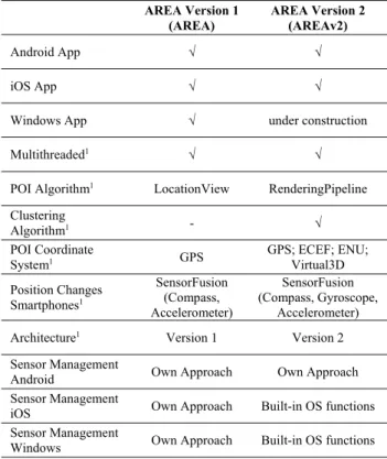
context of respective development projects, three fundamental issues, not properly covered by the first version of the AREA kernel, emerged. First, the heterogeneous characteristics of the various mobile operating systems need to be taken into account more explicitly. Second, a potentially large number of POIs need to be handled more efficiently. Third, additional features demanded by mobile users are required. These insights, in turn, resulted in the development of AREA’s second kernel version (i.e. AREA Version 2). Table 1 summarizes the evolution of AREA from its first to its second version.
Table 1. AREA Versions
AREA Version 1 (AREA)
AREA Version 2 (AREAv2)
Android App √ √
iOS App √ √
Windows App √ under construction
Multithreaded1 √ √
POI Algorithm1 LocationView RenderingPipeline Clustering
Algorithm1 - √
POI Coordinate
System1 GPS GPS; ECEF; ENU;
Virtual3D Position Changes
Smartphones1
SensorFusion (Compass, Accelerometer)
SensorFusion (Compass, Gyroscope,
Accelerometer) Architecture1 Version 1 Version 2 Sensor Management
Android Own Approach Own Approach
Sensor Management
iOS Own Approach Built-in OS functions Sensor Management
Windows Own Approach Built-in OS functions ENU=East-North-Up Coordinate System, ECEF=Earth-Centered Earth-Fixed Coordinate System, GPS=Global Positioning System,
1= all mobile OS
The heterogeneous characteristics of the mobile operating systems as well as performance issues with many POIs are addressed by the development of a new kernel and architecture called AREA Version 2 (AREAv2) (cf. Table 1, AREAv2).
Moreover, AREAv2 provides three new features. The first one deals with so-called POI clusters. If a huge number of POIs causes many overlaps on the camera view, it is difficult for users to precisely interact with single POIs inside such cluster.
In order to precisely select a single POIs inside a cluster, a new feature was developed. The second feature we developed connects POIs through lines in order to visualize tracks. For example, such a track may be used as the cycle path a user wants to perform in a certain area. The third feature highlights areas (e.g., football fields). From a technical perspective, the added features are demanding if they shall be supported in the same manner on different mobile operating systems.
This work presents fundamental concepts developed in the context of AREA Version 2 (AREAv2). Section 2 discusses related work. Section 3 presents the architecture of AREAv2. In Section 4, the coordinate system used by AREAv2 is introduced, while Sections 5 and 6 present the algorithms for POI and cluster handling. Conducted performance tests with AREAv2 are presented in Section 7, while Section 8 illustrates the use of AREAv2 in practical scenarios. Section 9 concludes the paper.
2. Related Work
Previous research related to the development of a location- based augmented reality application in non-mobile environments is described in [4]. In turn, [5] uses smart mobile devices for developing an augmented reality system. The augmented reality application described in [6] allows sharing media data and other information in a real-world environment and enables users to interact with this data through augmented reality. However, none of these approaches share insights regarding the development of location-based augmented reality on smart mobile devices as AREAv2 does. Only little work exists, which deals with the engineering of mobile augmented reality systems in general. As an exception, [7] validates existing augmented reality browsers. Moreover, [8] discusses various types of location-based augmented reality scenarios.
More precisely, issues that have to be particularly considered for a specific scenario are discussed in more detail. However, engineering issues of mobile applications are not considered.
In [9], an authoring tool for mobile augmented reality applications, which is based on marker detection, is proposed.
In turn, [12] presents an approach for indoor location-based mobile augmented reality. Furthermore, [13] gives an overview of various aspects of mobile augmented reality for indoor scenarios. Another scenario for mobile augmented reality is presented in [17]. The authors use mobile augmented reality for image retrieval. However, [9, 12, 13, 17] do not address engineering aspects of location-based mobile applications. In [10], an approach supporting pedestrians with location-based mobile augmented reality is presented. Finally, [14] deals with a client and server framework enabling location-based applications. Altogether, neither software vendors nor research projects provide insights regarding the engineering of a location-based mobile augmented reality kernel.
3. Architecture
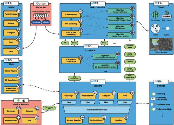
The AREAv2 architecture, which significantly enhances the architecture of the first kernel version [1, 2, 11], is depicted in Fig. 1. The architecture comprises nine major components (cf.
Fig. 1). The Model component manages POIs, POI categories (e.g., all POIs that represent restaurants), POI clusters, POI tracks (e.g., cycle paths), and POI areas (e.g., football fields).
Developers may use this component to integrate application- specific POI categories as well as to change the visualization of the provided POI features. The Places API component, in turn, allows displaying POIs provided by Google or other remote APIs. Note that this component was integrated to be able to test the kernel with large numbers of POIs or POI clusters more easily. As AREAv2 shall also work without online connection, the used POIs are locally stored on the smart mobile device. The local database, however, may be synchronized with a remote database. Due to lack of space, the components for storing POIs locally and synchronizing them with a remote database are excluded here and, hence, are not depicted in Fig. 1. The Math component, in turn, provides functions for calculations in the coordinate systems used.
Compared to AREA, AREAv2 uses a novel sensor fusion approach that provides a more precise positioning of POIs through the Sensor component. In this context, four sensors are considered on all supported mobile operating systems, i.e., gyroscope, compass, accelerometer, and GPS (cf. Fig. 1). The Location component provides algorithms for handling the different coordinate systems. Their results, combined with the ones of the Sensor component, are used by the Main component. The latter provides algorithms that enable the handling of the POI-related features.
Fig. 1. AREAv2 Architecture
Furthermore, the View component enables required visu- alizations, i.e., visualizations of POIs, POI labels, POI clusters, POI tracks, POI areas, a POI radar, and a POI radius. The radar can be used to check whether POIs, which are currently not displayed on the screen of the smart mobile device, can be accessed when pointing with the smart mobile device towards another direction. The radius, in turn, can be used to specify the maximum distance the mobile user may have to the POIs that shall be displayed. By calculating the distance between the device and the POIs based on the coordinate system, AREAv2 can determine the POIs located inside the chosen radius and, hence, the POIs to be displayed on the screen. Finally, the Settings component realizes functions enabling users to customize AREAv2 features (cf. Fig. 1).
4. Coordinate System
AREAv2 is based on a coordinate system that differs from the one used in the first kernel version, which was solely based on GPS coordinates. More precisely, in AREA, the GPS coordinates of mobile users were calculated by using the GPS sensor of their smart mobile devices, whereas the GPS coordi- nates of the POIs were retrieved from the local database. Based on the comparison of mobile user and POI coordinates as well as proper calculations (e.g., to determine whether the device is held obliquely), the POIs can be correctly displayed in the camera view of the smart mobile device. The core idea of AREAv2, in turn, is based on five aspects necessitating the use of another coordinate system. First, a virtual 3D world is used to relate the user's position to the one of the POIs. Second, the user is located at the origin of this world. Third, instead of the
physical camera, a virtual 3D camera is used that operates with the created virtual 3D world. Therefore, the virtual camera is placed at the origin of this world. Fourth, the sensor charac- teristics of the supported mobile operating systems need to be properly covered in order to enable the virtual 3D world.
Regarding iOS, sensor data of the gyroscope as well as the accelerometer are used, whereas for Android sensor data of the gyroscope, accelerometer and compass of the mobile device are used to position the virtual 3D camera correctly. Fifth, the physical camera of the mobile device is adjusted to the virtual 3D camera by analyzing sensor data. In order to realize the 3D world of AREAv2, a complex coordinate system, which consists of three sub-systems, is required. The first sub-system uses GPS, ECEF (Earth-Centered, Earth-Fixed), and ENU (East, North, Up) coordinates.1 The second one, in turn, relies on a virtual 3D space with the user being located at the origin.
Finally, the third sub-system uses a virtual 3D camera located at the origin of the 3D world. Note that the first sub-system (with GPS, ECEF, and ENU coordinates) constitutes a prerequisite (cf. Fig. 2) for transforming sensor data of the smart mobile device into data that can be used for the virtual 3D world.
As illustrated in Fig. 2, the user is located at the ECEF origin (0, 0, 0). The POIs, in turn, are located on the surface of the earth, again using ECEF coordinates. To use this metaphor for the virtual 3D world, two additional transformations became necessary. As a smart mobile device can only sense GPS coordinates, first of all, the GPS coordinates of the user and the POIs need to be transformed into ECEF coordinates.
Second, as a user cannot be physically located at the origin of the earth, ECEF coordinates need to be transformed into ENU coordinates. The latter, in turn, allow for the described
1See https://en.wikipedia.org/wiki/ECEF and https://en.wikipedia.org/wiki/East_north_up
metaphor of the virtual 3D world. More precisely, ENU coordinates are transformed into coordinates for the virtual 3D world through a transformation of axes. Finally, the distance between a user and the POI based on ENU coordinates must be calculated. The three algorithms accomplishing the required conversions can be found in [11].
Fig. 2. ECEF and ENU Coordinate Systems
5. Points of Interest Algorithm
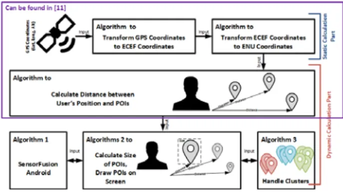
Although AREAv2 uses a virtual 3D world for displaying POIs, the direction in which a user holds his smart mobile device must be properly determined. For example, if the smart mobile device is held obliquely, the POI needs to be correctly positioned within the virtual 3D world. As the algorithm to correctly position POIs (the POI algorithm) requires calculations from other algorithms, Fig. 3 illustrates the dependencies to them. Note that Algorithm 2 constitutes the POI algorithm. It establishes the coordinate system on one hand and is the base for the clustering algorithm on the other.
In general, Algorithm 2 depends on three Algorithms presented in [11]. On Android, Algorithm 2 additionally depends on Algorithm 1. Algorithm 2 uses the following inputs: First, the list of POIs poiList (i.e., the ENU coordinates), locally stored on the smart mobile device, is used. Each time a user changes the position of his smart mobile device, all POI ENU coordinates are recalculated.
Fig. 3. Algorithm Dependencies
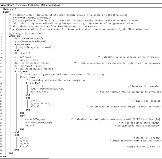
Second, a rotation matrix rotationMatrix RM is used that manages relevant sensor data. Regarding iOS, for example, the data of the gyroscope and accelerometer are used, whereas on Android the data of the gyroscope and accelerometer, plus additional compass data, are utilized. More precisely, in order to obtain the attitude of the mobile device relative to true north as a rotation matrix, we utilize the CMMotionManager API provided by Apple iOS. Regarding Android, however, we were unable to retrieve any reliable data when using the Android standard API. Hence, we decided to develop a more reliable sensor fusion algorithm to obtain a similar rotation matrix like on iOS (cf. Algorithm 1). Algorithm 1 accomplishes this task:
First, the Android gyroscope provides inappropriate (i.e., inaccurate) values. As a consequence, when using (a) the values of the gyroscope for a user that (b) frequently changes the position of his Android smart mobile device, the POIs on the screen of his smart mobile device oscillate badly. To obtain better user experience, we smooth the gyroscope values by using the SLERP algorithm [16] (cf. Algorithm 1, Line 28).
Second, the rotation vector provided by the Android mobile OS is very precise on one hand, but it is prone to (1) frequent position changes, (2) slow position changes, and (3) magnetic interference sources on the other. Therefore, we use the gyroscope instead of the rotation vector to calculate rotationMatrix RM as the gyroscope provides more appropriate values (cf. Algorithm 1, Lines 9-13).
Algorithm 2: Rendering pipeline with redraw up to 60 times per second Data: poiList, rotationMatrix RM, cameraView CM
1 begin
2 P ← CM ·RM; / * Multiply camera matrix with r o t a t i o n matrix t o r e t r i e v e r o t a t e d camera p r o j e c t i o n ma t r i x . * /
foreach poi ∈ poiListdo 3
4 ← [poi.ENU.E, poi.ENU.N, poi.ENU.U, 1] ; / * Create homogeneous v ec t o r out o f t h e POI’s ENU c o o r d i n a t e .
* /
5 ← ·P ; / * M u l t i p l i c a t i o n o f v ec t o r with p r o j e c t i o n matrix t o p r o j e c t t h e p o s i t i o n o f t h e POI onto t h e camera view frustum. * /
/ * Normalize v e ct o r components t o 0 . . . 1 * / / * Normalize v e ct o r components t o 0 . . . 1 * / z ← .z
if .z< −1 then
trans f ormAndMovePOI(poi,x,y); poi.visible =true;
/ * POI i s lo c a te d i n f r o n t of t h e camera. * / / * P o s i t i o n POI on t h e screen o f t h e u s e r and make i t v i s i b l e . * / end
else
poi.visible = f alse end
6 7 8 9 10 11 12 13 14 15
16 end
17 end
x← ( ( . / . ) + 1.0) * 0.5 y←( ( . / . ) + 1.0) * 0.5
In turn, the gyroscope poses the so-called DRIFT effect2 over time. To cope with the latter effect, every 10 seconds the rotation vector is set as the new reference position (cf.
Algorithm 1, Lines 14-38). Within these 10 seconds, we check whether the gyroscope and the rotation vector differ too much.
In the latter case, we increase a counter. Based on a threshold that is compared to the counter, we either use the gyroscope or the rotation vector for the rotationMatrix RM. On Android, this approach for displaying POIs results in similar user experiences compared to iOS. Third, the rotationMatrix RM is used to adjust the virtual camera managed with the matrix cameraView CM. This matrix, in turn, is used to decide which POIs are actually displayed on the camera view. Based on the poiList, the rotationMatrix RM, and the cameraView CM, Algorithm 2 works as follows3: A view called areaview is created and shown to the user. Next, each POI in poiList is created as a separate view. These POI views are then placed on the areaview and are initially marked as invisible. In the following, they will be only displayed if Algorithm 2 indicates that they shall be visible (cf. Algorithm 2, Lines 9-15). Note that the entire view structure is pre-calculated and will not be changed afterwards by Algorithm 2. The latter makes POIs visible or invisible taking the position changes of the user into account. The position, in turn, is determined through the rotation matrix rotationMatrix RM (cf. Algorithm 2, Lines 2- 8). Changes in rotationMatrix RM are evaluated up to 60 times per second. Hence, the pre-calculation of the view structure with respect to performance is indispensable.
6. Cluster Algorithm
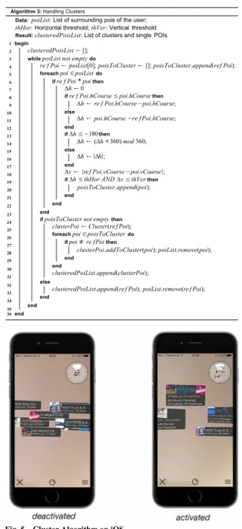
Algorithm 3 presents the calculation how POI clusters are handled. The algorithm utilizes parameters thHor and thVer to identify POI clusters contained in poiList. These two parameters, in turn, are defined by the mobile users themselves and are applied as follows: all POIs being inside an area spanned by thHor on the horizontal and thVer on the vertical course (i.e., in the ENU coordinate system) are considered as POIs belonging to the same cluster. Figs. 4 and 5 illustrate how cluster handling looks like from the perspective of the mobile user. More precisely, in both figures the screens marked deactivated show POIs without using Algorithm 3.
Consequently, the POIs are difficult to select for mobile users.
In turn, the screens marked activated in Figs. 4 and 5 show Algorithm 3 in practice; i.e., a cluster was detected and the POIs are arranged more conveniently to the mobile user.
Fig. 4. Cluster Algorithm on Android OS
2 http://sensorwiki.org/doku.php/sensors/gyroscope
3 Note that parts of the algorithm concept can be related to perspective transformation and clipping in the context of rendering pipeline in 3D computer graphics.
Algorithm 3: Handling Clusters
Data: poiList: List of surrounding pois of the user;
thHor: Horizontal threshold; thVer: Vertical threshold Result: clusteredPoisList: List of clusters and single POIs 1 begin
clusteredPoisList ←[]; while poiList not emptydo
re f Poi ← poiList[0]; poisToCluster ← []; poisToCluster.append(ref Poi); foreach poi ∈ poiListdo
if re f Poi *poi then
∆h ←0
if re f Poi.hCourse ≤ poi.hCoursethen else
∆h ← re f Poi.hCourse− poi.hCourse;
∆h ← poi.hCourse − re f Poi.hCourse;
end
if ∆h ≤ −180then else
∆h ← (∆h +360) mod 360;
∆h ←|∆h|;
end
∆v ← |re f Poi.vCourse− poi.vCourse|; if ∆h ≤ thHor AND ∆v ≤ thVerthen
poisToCluster.append(poi);
end end end
if poisToCluster not emptythen clusterPoi←Cluster(re f Poi);
foreach poi ∈ poisToClusterdo if poi ≠re fPoi then
clusterPoi.addToCluster(poi);poiList.remove(poi);
end end
clusteredPoiList.append(clusterPoi);
else
clusteredPoiList.append(re f Poi);poiList.remove(re f Poi);
end 2
3 4 5 6 7 8 9 10 11 12 13 14 15 16 17 18 19 20 21 22 23 24 25 26 27 28 29 30 31 32 33 34
35 end
36 end
Fig. 5. Cluster Algorithm on iOS
7. Experimental Results
In order to evaluate various performance indicators of AREAv2 and to compare them with the ones of competitive location-based mobile augmented reality applications, we conducted an experiment obeying the following steps:
(1) Determine performance indicators for both the Android and the iOS version of AREAv2: CPU usage, memory usage, and battery consumption.
(2) Compare the performance indicators with the ones of well-known smart mobile applications providing location-based mobile augmented reality as well.
(3) Define an experiment setting for using the smart mobile devices in two different scenarios: (a) Holding the smart mobile device without performing any position change; (b) Continuously moving the smart mobile device.
Concerning (1), we use an Apple iPhone 5c (iOS Version 9.3.5) for the AREAv2 iOS version and a Google Nexus 5 (Android Version 6.0.1) for the AREAv2 Android version.
Concerning (2), in turn, we compared AREAv2 with the smart mobile applications depicted in Table 2.
As further shown in Table 2, we also determined the aforementioned performance indicators for the camera as well as the main menu of the two smart mobile devices. Camera means that solely the camera function of the smart mobile device was started without using a particular smart mobile application. Main menu, in turn, means that the main menu of AREAv2 was opened without using the augmented function.
These two measurements were accomplished to enable a better comparison of the three performance indicators.
Table 2. Experimental Mobile Applications
iPhone 5c Nexus 5
Static (a) Moving (b) Static (a) Moving (b)
AREAv2 x x x x
Yelp [15] x x - -
Wikitude [18] x x x x
Augmented3D [19] x x x x
Camera x o x o
Main Menu x o x o
"x": performed, "o": not performed, "-": not available Concerning (3), the following experimental setting was established: for the static Scenario (a), a vice was used (cf. Fig.
6) to simulate a user holding the smart mobile device without any position change.
Fig. 6. Simulation of Static Scenario (a)
For simulating a user continuously moving his smart mobile device (Scenario (b)), we used a ventilator (cf. Fig. 7).
Fig. 7. Simulation of Moving Scenario (b)
For properly measuring the above mentioned three performance indicators, we used the SystemPanel App [20] for Android and the Instruments Framework [21] for iOS.
Based on this overall setting, each application was evaluated using the same experiment procedure:
1. The smart mobile device was set to factory defaults.
2. The smart mobile application and the monitoring app were downloaded.
3. All other mobile applications that may be manually closed by a user (i.e., except the background processes) were terminated.
4. The battery was loaded to 100%.
5. The smart mobile device was mounted to the vice or ventilator.
6. The two mobile applications (i.e., test and monitoring application) were started.
7. The experiment was conducted over a period of 30 minutes.
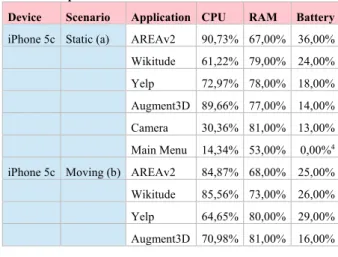
Table 3 shows the results of the experiment. For each tested application, the average value of a performance indicator during the 30-minutes experiment is shown. Note that the three applications AREAv2, Wikitude and Yelp provide the same location-based mobile augmented reality functions, whereas Augmented3D uses 3D models in the augmented view (i.e., the camera view). The latter application was evaluated to obtain insights into location-based mobile augmented reality applications in comparison to object-based mobile augmented reality applications.
Experimental results indicate that AREAv2 shows a better performance than the tested commercial location-based mobile augmented reality applications Wikitude and Yelp as well as Augmented3D. Only for the static iOS scenario, AREAv2 shows a higher CPU usage compared to the commercial applications. We currently conduct further tests to evaluate this issue in more detail. Regarding the RAM performance indicator, AREAv2 performs best in all scenarios. Regarding the CPU indicator, in turn, AREAv2 only shows weaker results for the iOS static scenario and the iOS moving scenario (when comparing it with Yelp). Concerning battery consumption, AREAv2 performs worse than the other mobile augmented reality applications. To address the latter aspect, we currently work on AREAv3. As shown in Table 3, we have implemented a first version of AREAv3 on Android. First results indicate that AREAv3 performs better than AREAv2 as well as all other mobile augmented reality applications with respect to the overall battery consumption.
Table 3. Experiment Results
Device Scenario Application CPU RAM Battery iPhone 5c Static (a) AREAv2 90,73% 67,00% 36,00%
Wikitude 61,22% 79,00% 24,00%
Yelp 72,97% 78,00% 18,00%
Augment3D 89,66% 77,00% 14,00%
Camera 30,36% 81,00% 13,00%
Main Menu 14,34% 53,00% 0,00%4 iPhone 5c Moving (b) AREAv2 84,87% 68,00% 25,00%
Wikitude 85,56% 73,00% 26,00%
Yelp 64,65% 80,00% 29,00%
Augment3D 70,98% 81,00% 16,00%
4Reported by the Instruments Framework [21] to 0,00%
Camera 30,36% 81,00% 13,00%
Main Menu 14,34% 53,00% 0,00%5 Nexus 5 Static (a) AREAv2 67,20% 46,00% 34,00%
AREAv3 41,52% 40,00% 19,00%
Wikitude 67,44% 48,00% 32,00%
Augment3D 70,28% 50,00% 25,00%
Camera 22,37% 49,00% 14,00%
Main Menu 8,91% 41,00% 6,00%
Nexus 5 Moving (b) AREAv2 59,22% 50,00% 34,00%
AREAv3 49,72% 73,00% 23,00%
Wikitude 64,93% 48,00% 30,00%
Augment3D 70,45% 48,00% 33,00%
Camera 22,37% 49,00% 14,00%
Main Menu 8,91% 41,00% 6,00%
5Reported by the Instruments Framework [21] to 0,00%
8. AREAv2 in Practice
Table 4 summarizes examples of mobile applications that were developed with the AREAv2 framework. As can be seen, AREAv2 has been applied in various scenarios of everyday life (cf. Table 4). Considering the high number of mobile applications implemented with AREAv2, the practical applicability of the latter could be demonstrated. The numbers of POIs considered by the respective mobileapplications vary among the scenarios, but in all scenarios AREAv2 revealed same performance experience.
Table 4. AREAv2 in Practice Apps
using AREAv2 Cate-
gory iOS Android #POIs Cluster Handl.
Abfallinfo
HOK I √ √ 190 √
Altenahr C √ √ 964 √
Bad Waldsee C √ √ 624 √
Bühlerzell C √ √ 306 √
Gaildorf C √ √ 457 √
Goldpartner F √ √ 205 √
Algorithm 1: Determine 3D-Rotation Matrix on Android Data: , , R
1 begin
/ * RotationVector: Rotation o f t h e smart mobile device with angle θ t o t h e t h r e e a x e s:
x∗sin(θ/2),y∗sin(θ/2),z∗sin(θ/2).
/ * GyroscopeVector: Vector with r o t a t i o n o f t h e smart mobile device t o t h e t h r e e axes i n rad/s / * Mg : Matrix r e p r e s e n t a t i o n o f t h e gyroscope v e c t o r , qg : Quaternion o f t h e gyroscope v ec t o r / * Mr : Matrix r e p r e s e n t a t i o n o f t h e Rot at ionVector, t: timestamp
/ * qr Quaternion o f t h e RotationVect or, R: Smart mobile device r o t a t i o n provided by t h e 3D r o t a t i o n matrix
* /
* /
* /
* /
* / Mg ← 0, qg ← 0 ,t ← 0, f ←0
while 1do
Mr ←MatrixFromVector( ) qr ←QuaternionFromVector( ) if first runthen
Mg ← Mr , qg ← qr , t ←now() end∆t ← now() −t
/ * Ca l c u l at e t h e angul ar speed o f t h e gyroscope * / s2 ← sin s1 , s3 ← coss1
∆qg ← (s2 ∗gˆ x , s2 ∗gˆy , s2 ∗gˆz , s3 ); / * Create a quaternion from t h e angular r o t a t i o n o f t h e gyroscope * /
2 3 4 5 6 7 8 9 10 11 12
13 qg ← ∆qg ∗qg , d ← qg ·qr
/ * Time t h re sh o l d not reached * /
14 if t < εt then
* /
15
/ * Di r e c t i o ns o f gyroscope and r o t a t i o n v ec t o r d i f f e r t o st ro ng . . . if d < εd then
/ * . . . b u t they did not d i f f e r o ft e n enough ye t * / if f < εf then
f ← f + 1; / * In cr e as e f a i l counter * /
∆Mg ← MatrixFromVector(∆qg)
R ← ∆Mg ∗Mg; / * Set 3D Rotation Matrix according t o gyroscope * /
end else
f ← 0; / * Reset f a i l count er * /
qg ← qr , Mr ←Mg
R ← Mr; / * Set 3D Rotation Matrix accordi ngly t o r o t a t i o n v e c t or * / end
end else
← S LERP(qg,qr) ; R ← MatrixFromVector( ) ; Mg ← R;
/ * C a l c u l at e t h e i n t e r p o l a t e d o r i e n t a t i o n with SLERP algorithm [1 6 ] * / / * Assign t h e 3D r o t a t i o n Matrix * / / * Set gyroscope matrix accordingl y * / end
end else
f ← 0; qg ← qr;
/ * Reset f a i l counter * / / * Align gyroscope with r o t a t i o n v e c t o r * / Mg ←Mr
R ← Mr; / * Assign 3D r o t a t i o n matrix * /
end 16
17 18 19 20 21 22 23 24 25 26 27 28 29 30 31 32 33 34 35 36 37 38
39 end
40 end
s1← ( * ∆t) ∕ 2
Hinterzarten C √ √ 297 √
Liveguide
Muswiese E √ √ 97 √
Mühlenbecker
Land C √ √ 496 √
Liveguide
Gaildorf E √ √ 44 √
Rechberghausen C √ √ 331 √
Riedlingen C √ √ 781 √
Renningen C √ √ 1048 √
9. Summary and Outlook
This paper gave insights into the development of a powerful augmented reality kernel for smart mobile devices. In turn, this kernel serves as the core of an engineering framework for mobile augmented reality applications. We discussed complexity issues emerging in this context, showing that the development of mobile augmented reality applications constitutes a challenging endeavor. As a particular lesson, we learned that fundamental components of the kernel needed to be evolved over time in order to keep pace with the frequently changing requirements of mobile operating systems. In addition, novel functions like POI cluster handling were presented. In general, the development of mobile applications is demanding when considering the peculiarities of the different mobile operating systems. To cope with this heterogeneity, AREAv2 is based on a modular architecture.
We further showed that sophisticated business applications can be realized on top of AREAv2. Furthermore, experimental results demonstrated that AREAv2 had shown a good performance compared to competitive location-based mobile augmented reality applications.
Altogether, mobile augmented reality enables scenarios demonstrating that mobile applications are becoming increasingly mature. However, suitable concepts are needed to enable comprehensive and efficient mobile assistance in everyday life.
References
[1] Schickler, M., Pryss, R., Schobel, J., Reichert, M.. An engine enabling location-based mobile augmented reality applications. In: 10th Int’l Conf on Web Information Systems and Technologies (Revised Selected Papers); no.
226 in LNBIP. Springer; 2015, p. 363–378.
[2] Geiger, P., Schickler, M., Pryss, R., Schobel, J., Reichert, M.. Location-based mobile augmented reality applications: Challenges, examples, lessons learned. In:
10th Int’l Conf on Web Information Systems and Technologies. 2014, p. 383–394.
[3] Jabeur, N., Haddad, H., Boulkrouche, B.. Cyber-Physical Spatial Decision Support System for Road Traffic Management. International Journal of Ubiquitous Systems and Pervasive Networks; 2016; 7(2) :1–7.
[4] Kooper, R., MacIntyre, B.. Browsing the real-world wide web: Maintaining awareness of virtual information in an ar information space. Int’l Journal of Human-Computer Interaction 2003;16(3):425–446.
[5] Kähäri, M., Murphy, D.. Mara: Sensor based augmented reality system for mobile imaging device. In: 5th IEEE and ACM Int’l Symp on Mixed and Augmented Reality;
vol. 13. 2006.
[6] Lee, R., Kitayama, D., Kwon, Y., Sumiya, K..
Interoperable augmented web browsing for exploring virtual media in real space. In: Proc of the 2nd Int’l Workshop on Location and the Web. ACM; 2009, p. 7.
[7] Grubert, J., Langlotz, T., Grasset, R.. Augmented reality browser survey. Technical Report; Graz University of Technology; 2011.
[8] Kim, W., Kerle, N., Gerke, M.. Mobile augmented reality in support of building damage and safety assessment.
Natural Hazards and Earth System Sciences 2016;16(1):287.
[9] Yang, Y., Shim, J., Chae, S., Han, T.. Mobile augmented reality authoring tool. In: 10th IEEE Int’l Conf on Semantic Computing. IEEE; 2016, p. 358–361.
[10] Chung, J., Pagnini, F., Langer, E.. Mindful navigation for pedestrians: Improving engagement with augmented reality. Technology in Society 2016;45:29–33.
[11] Pryss, R., Geiger, P., Schickler, M., Schobel, J., &
Reichert, M. (2016). Advanced Algorithms for Location- Based Smart Mobile Augmented Reality Applications.
Procedia Computer Science, 94, 97-104.
[12] Paucher, R., & Turk, M. (2010). Location-based augmented reality on mobile phones. In 2010 IEEE Computer Society Conference on Computer Vision and Pattern Recognition-Workshops (pp. 9-16). IEEE.
[13] Reitmayr, G., & Schmalstieg, D. (2003). Location based applications for mobile augmented reality. In Proceedings of the Fourth Australasian user interface conference on User interfaces 2003-Volume 18 (pp. 65-73). Australian Computer Society, Inc.
[14] Capece, N., Agatiello, R., & Erra, U. (2016, July). A client-server framework for the design of geo-location based augmented reality applications. In Information Visualisation (IV), 2016 20th International Conference (pp. 130-135). IEEE.
[15] Yelp. https://www.yelp.com/mobile. [Online; accessed on 06-January-2017]
[16] Shoemake, K. (1985, July). Animating rotation with quaternion curves. In ACM SIGGRAPH computer graphics (Vol. 19, No. 3, pp. 245-254). ACM.
[17] Lee, Y. H., & Rhee, S. B. (2015). Efficient Photo Image Retrieval System Based on Combination of Smart Sensing and Visual Descriptor. Intelligent Automation & Soft Computing, 21(1), 39-50.
[18] Wikitude. http://www.wikitude.com/. [Online; accessed on 30-April-2017]
[19] Augment3D. Google Android Store Mobile Application:
https://play.google.com/store/apps/details?id=com.ar.aug ment&hl=de; Apple iOS Store Mobile Application:
https://itunes.apple.com/de/app/augment-3d-augmented- reality/id506463171?mt=8. [Online; accessed on 30-April- 2017]
[20] SystemPanel Smart Mobile Android Store Application:
https://play.google.com/store/apps/details?id=nextapp.syst empanel.r1&hl=de. [Online; accessed 30-April-2017]
[21] Instruments performance-analysis and testing tool.
https://developer.apple.com/library/content/documentation /DeveloperTools/Conceptual/InstrumentsUserGuide/
[Online; accessed on 30-April-2017]