Trapping of dilute quantum-degenerate gases in ultra-shallow magnetic traps under microgravity conditions
DISSERTATION
zur Erlangung des akademischen Grades doctor rerum naturalium
(Dr. rer. nat.) im Fach Physik eingereicht an der
Mathematisch-Naturwissenschaftlichen Fakultät I Humboldt-Universität zu Berlin
von
Herr Dipl.-Phys. Wojciech Lewoczko-Adamczyk geboren am 01.07.1979 in Koszalin (Polen)
Präsident der Humboldt-Universität zu Berlin:
Prof. Dr. Dr. h.c. Christoph Markschies
Dekan der Mathematisch-Naturwissenschaftlichen Fakultät I:
Prof. Dr. Lutz-Helmut Schön Gutachter:
1. Prof. Dr. Achim Peters 2. Prof. Dr. Ernst Rasel 3. Prof. Dr. Hanspeter Helm
eingereicht am: 19.12.2007
Tag der mündlichen Prüfung: 16.03.2009
Recently, cooling, trapping and manipulation of neutral atoms and ions has become an especially active field of quantum physics. The main motiva- tion for the cooling is to reduce motional effects in high precision measure- ments including spectroscopy, atomic clocks and matter interferometry. The spectrum of applications of these quantum devices cover a broad area from geodesy, through metrology up to addressing the fundamental questions in physics, as for instance testing the Einstein’s equivalence principle. However, the unprecedented precision of the quantum sensors is limited in terrestial laboratories. Freezing atomic motion can be nowadays put to the limit at which gravity becomes a major perturbation in a system. Gravity can sig- nificantly affect and disturb the trapping potential. This limits the use of ultra-shallow traps for low energetic particles. Moreover, free particles are accelerated by gravitational force, which substantially limits the observation time.
Targeting the long-term goal of studying cold quantum gases on a space platform, we currently focus on the implementation of a Bose-Einstein con- densate (BEC) experiment under microgravity conditions at the drop tower in Bremen. Special challenges in the construction of the experimental setup are posed by a low volume of the drop capsule as well as critical decelerations up to 50g during recapture at the bottom of the tower. All mechanical and electronic components were thus been designed with stringent demands on miniaturization and mechanical stability.
This work reports on the observation of a BEC released from an ultra- shallow magnetic potential and freely expanding for one second. Both, the low trapping frequency and the long expansion time are not achievable in any earthbound laboratory. This unprecedented time of free evolution leads to new possibilities for the study of BEC-coherence. It can also be applied to enhance the sensitivity of inertial quantum sensors based on ultra-cold matter waves.
Keywords:
Bose-Einstein condensate, microgravity, magnetic trap, atom-chip
Ultra-kalte atomare Gase werden in zahlreichen Laboren weltweit untersucht und finden unter anderem Anwendung in Atomuhren und in Atominterferom- eter. Die Einsatzgebiete erstrecken sich von der Geodäsie über die Metrologie bis hin zu wichtigen Fragestellungen der Fundamentalphysik, wie z.B. Tests des Äquivalenzprinzips. Doch die beispiellose Messgenauigkeit ist durch die irdische Gravitation eingeschränkt. Zum einen verzerrt die Schwerkraft das Fallenpotential und macht damit die Reduktion der atomaren Energie unter einem bestimmten Limit unmöglich. Zum anderen werden die aus einer Falle frei gelassenen Teilchen durch die Erdanziehung beschleunigt und so ist deren Beobachtungszeit begrenzt.
Im Rahmen dieser Arbeit werden die Ergebnisse des Projektes QUAN- TUS (Quantengase Unter Schwerelosigkeit) dargestellt. Auf dem Weg zur Implementierung eines Quantengasexperimentes im Weltraum wurde inner- halb einer deutschlandweiten Zusammenarbeit eine kompakte, portable und mechanisch stabile Apparatur zur Erzeugung und Untersuchung eines Bose- Einstein-Kondensats (BEC) unter Schwerelosigkeit im Fallturm Bremen en- twickelt. Sowohl die Abbremsbeschleunigung von bis zu 50 g als auch das begrenzte Volumen der Fallkapsel stellen hohe Ansprüche an die mechanische Stabilität und die Miniaturisierung von optischen und elektronischen Kom- ponenten. Der Aufbau besteht aus einer im ultra-hoch Vakuum geschlosse- nen magnetischen Mikrofalle (Atomchip) und einem kompakten auf DFB- Dioden basierenden Lasersystem. Mit diesem Aufbau ließ sich das erste BEC unter Schwerelosigkeit realisieren und nach 1 Sekunde freier Expan- sion zu beobachten. Weder die schwache Krümmung des Fallenpotentials noch die lange Beobachtungszeit würden in einem erdgebundenen Experi- ment realisierbar.
Die erfolgreiche Umsetzung des Projektes eröffnet ein innovatives Forschungs- gebiet - degenerierte Quantengase bei ultratiefen Temperaturen im pK-Bereich, mit großen freien Evolutions- und Beobachtungszeiten von mehreren Sekun- den.
Schlagwörter:
Bose-Einstein Kondensat, Schwerelosigkeit, magnetische Falle, Atom-Chip
Dla kochanych rodziców.
iv
1 From Quantum to Cosmos 1
1.1 Introduction . . . 1
1.2 Bose-Einstein condensate . . . 3
1.3 Disadvantages of the gravity . . . 5
1.3.1 Short observation time . . . 5
1.3.2 Deformation of the trapping potential . . . 5
1.3.3 Limited trap flatness . . . 6
1.4 Advantages of the space environment . . . 7
1.4.1 Atomic clocks . . . 8
1.4.2 Atom interferometers . . . 9
1.4.3 Benefits for the fundamental research . . . 11
1.5 Existing cold atom platforms in microgravity . . . 13
1.5.1 Experiments in the parabolic flights . . . 13
1.5.2 ACES / PHARAO . . . 13
1.5.3 QUANTUS . . . 14
1.6 Composition of this thesis . . . 16
2 Cold atom experiment at the Drop Tower in Bremen 18 2.1 The drop tower Bremen . . . 18
2.2 Requirements on the experiment . . . 21
2.3 Quantus experimental setup . . . 23
2.3.1 Drop capsule overview . . . 23
2.3.2 Vacuum . . . 24
2.3.3 Chip trap and mirror MOT . . . 25
2.3.4 Laser system . . . 26
2.3.5 Drop capsule board computer . . . 39
2.4 Time sequence . . . 39
2.4.1 Doppler cooling in the magneto-optical trap . . . 40
2.4.2 Optical molasses . . . 42
2.4.3 Optical pumping . . . 43
2.4.4 Magnetic Z-trap . . . 44 v
2.4.7 Decompression . . . 46
2.4.8 Holding trap and free expansion . . . 48
3 Atom chip 49 3.1 Magnetic trapping of neutral atoms . . . 49
3.1.1 Magnetic potential . . . 50
3.1.2 Harmonic approximation . . . 51
3.1.3 Majorana losses . . . 51
3.2 Microchip traps . . . 52
3.2.1 Principle of operation . . . 53
3.2.2 Ideal H-trap . . . 57
3.2.3 Z-trap . . . 62
3.2.4 Quantus chip . . . 62
4 First observation of the Bose-Einstein condensate in micro- gravity 66 4.1 Evolution of the BEC in a time dependent trap . . . 66
4.1.1 Thomas-Fermi approximation . . . 67
4.1.2 Time dependent potential . . . 68
4.1.3 Generalization to a rotating trap . . . 69
4.2 Evolution of the trapping potential . . . 69
4.2.1 Adiabatic decompression of the trap . . . 69
4.2.2 Shift of the trap center by decompressing . . . 71
4.2.3 Collective oscillation of the BEC in the decompressed trap . . . 73
4.3 Free expansion of the BEC in microgravity . . . 76
4.3.1 Center-of-mass motion . . . 76
4.3.2 Systematic errors . . . 76
4.3.3 Free (?) expansion . . . 81
5 Future perspective 85 5.1 BEC in a magnetic insensitive state . . . 85
5.2 Bragg diffraction of the condensate . . . 87
5.3 The QUANTUS II project . . . 89
Appendix 85
A Harmonic frequencies in a three-dimensional trap 93
vi
B.2 Infinitely flat conductor . . . 96 B.3 Approximating an arbitrary shape conductor with a chain of
thin straight wires . . . 97
C Technical drawings 99
vii
1.1 BEC released from the trap, falling in the gravity . . . 6
1.2 Deformation of a trap by the gravity . . . 6
1.3 BEC after 50 ms free expansion . . . 7
1.4 Atomic clock . . . 8
1.5 Mach-Zender atom interferometer . . . 10
1.6 First BEC in microgravity . . . 15
1.7 1 s expansion of the BEC . . . 16
2.1 Drop tower Bremen . . . 19
2.2 Waterfall amplitude spectrum of g . . . 20
2.3 Drop tower acceleration . . . 20
2.4 Schematic of the drop capsule . . . 21
2.5 QUANTUS drop capsule . . . 24
2.6 Vacuum chamber . . . 24
2.7 Mirror MOT . . . 25
2.8 D2 transition in rubidium . . . 27
2.9 Schematic of the laser system . . . 28
2.10 Mechanical mount of the laser system . . . 28
2.11 Linewidth of a DFB diode . . . 29
2.12 Master laser and MOPA . . . 31
2.13 AOM module . . . 32
2.14 Laser lock bandwidth . . . 33
2.15 Laser lock test on the mini drop tower . . . 34
2.16 Laser test at ZARM drop tower . . . 35
2.17 Block laser . . . 36
2.18 Laser lock test by the catapult launch . . . 37
2.19 U-MOT . . . 42
2.20 Initial magnetic trap . . . 44
2.21 Evaporative cooling . . . 45
2.22 Enhancement in phase-space density . . . 47
3.1 Larmor precession in a magnetic field . . . 50 viii
3.4 U- and Z-trap . . . 56
3.5 H-trap . . . 57
3.6 Cigar-like potential of the H-trap . . . 59
3.7 Tilt of the trap principal axis . . . 60
3.8 H-trap magnetic field . . . 60
3.9 Potentials of extremely decompressed H- and Z-trap . . . 62
3.10 Quantus chip . . . 63
3.11 Biot-Savart law . . . 64
3.12 Magnetic trap depth . . . 65
4.1 Validity of the Thomas-Fermi approximation . . . 68
4.2 Chip current and bias field by the decompression . . . 70
4.3 Trap decompression . . . 70
4.4 Adiabatic decompression of the trapping potential. . . 72
4.5 Calculated dipole oscillations . . . 73
4.6 Measured dipole oscillation . . . 75
4.7 Measured dipole oscillation in microgravity . . . 76
4.8 Center-of-mass position of the BEC during 1 s TOF . . . 77
4.9 Residual acceleration due to air friction . . . 78
4.10 Residual magnetic field in the drop tower . . . 79
4.11 Inaccuracy of a Helmoholtz coil . . . 80
4.12 Expansion of the BEC during 1 s TOF . . . 82
4.13 Expansion of a thermal cloud . . . 84
5.1 Adiabatic rapid passage . . . 87
5.2 Bragg scattering of the BEC . . . 88
5.3 Hybrid MOPA . . . 90
5.4 The next generation of the vacuum chamber . . . 91
B.1 A finite piece of a thin wire . . . 95
B.2 A finite piece of a flat wire . . . 96
B.3 Magnetic field of a finite piece of a flat wire . . . 98
B.4 Approximating a flat conductor with a chain of thin wires . . 98
C.1 Wire structure of the Quantus chip . . . 99
C.2 Lockbox circuit 1 . . . 100
C.3 Lockbox circuit 2 . . . 101
C.4 Scheme of the AOM module . . . 102
C.5 Optical components of the Quantus laser system . . . 104
C.6 MTS master laser . . . 105 ix
2.1 Dimensioning of the drop capsules . . . 22 2.2 Cooling phases . . . 41 3.1 IP coil trap from Amsterdam vs. Quantus chip . . . 53
x
From Quantum to Cosmos
1.1 Introduction
Human’s curiosity to go beyond the current frontiers is the main catalyst of progress. During one of his ”post-Nobel” lectures, Wolfgang Ketterle told a story of the people of a tropical tribe. They suffer from an awful heat, so they invent a fridge. Their motivation was just to cool drinking water, but to their surprise, they discover ice - a novel state of water!1
There are many examples in everyday life showing that technological im- provements revealed new phenomena, inspired new ideas, confirmed or de- throned well established theories. In physics, two such particularly rewarding trends have determined the way of making fundamental research in the last decades. The first is to still increase the energy of a system. New constituents of matter are sought for by colliding known particles accelerated to enormous energies in the TeV range. Incessant attempts to find the Higgs boson is an illustrative example here. On the other end of the energy scale there is a quest for achievement of ever lower temperatures. It was marked with im- portant discoveries in the last centuries, like gas to liquid phase transitions, superfluidity or superconductivity.
Recently, cooling, trapping and manipulation of neutral atoms and ions has become an especially active field of quantum physics. The main motiva- tion for the cooling is to reduce motional effects in high precision measure- ments including spectroscopy, atomic clocks and matter interferometry. The high speed of the atoms makes measurements difficult. The Doppler shift causes displacement and broadening of the spectral lines of thermal atoms.
1Based loosely on the lecture: ”Ultrakalte Quantengase: die kälteste Materie im Uni- versum” held by W. Ketterle in 2004 by a colloquium of the Physical Society of Berlin (PGzB).
1
Furthermore, the high atomic velocities limit the observation time and thus the spectral resolution. To give some numerical examples, air molecules at room temperature move with speeds on the order of 300 m/s. At this speed it takes the particles only 3 ms to pass through a 1 m long detecting device.
Cooling to 4 K, the temperature of liquid helium, would reduce the mean speed roughly 9 times only. Laser cooling allows one to slow neutral atoms to a speed as low as a few cm/s and the corresponding temperatures are in the µK range. Other powerful cooling technique, evaporative cooling can reduce this speed by another order of magnitude. At this low temperature some re- markable new phenomena appear: the wave nature of the particles becomes apparent. The de Broglie matter wavelength, given by λDB =h/p, where p is atomic momentum andhthe Planck constant, becomes comparable to the mean atom-atom separation and a phase transition to the Bose-Einstein con- densate occurs. Quantum degenerate matter of Bose-Einstein condensates forms the coldest objects in the universe with effective temperatures in the low nK range.
However, further reduction of the atomic energy is hardly possible. Freez- ing atomic motion can be nowadays put to the limit at which Earth’s gravity becomes a major perturbation in a system. Unlike electromagnetic forces, gravity cannot be controlled by experimentalists. Rather, it is a constant accompanying potential which has to be accounted for when trapping mas- sive particles. Inside of a closed trapping volume a trapping potential must feature a gradient that is larger than the gravitational force on the trapped atoms. This limits the usefulness of ultra-shallow traps for low energetic particles. In contrast, microgravity offers a significant potential to further extend the physics of degenerate quantum gases towards nowadays inaccessi- ble regimes of low energies and macroscopic dimensions of coherent matter- waves. Physics at the lower end of the energy scale might result in a dis- covery of ”ice in the fridge”. New phases of matter could be observed and physical phenomena, like weak, long-range magnetic dipole-dipole interac- tions [Stuhler et al., 2005; Schmaljohann et al., 2004], could be studied in the reduced-gravity environment. Moreover, in the absence of gravity the trapping potential can be completely switched off. This will allow for an enhancement of the free evolution time of the released sample by many or- ders of magnitude. Longer observation times are crucial for increasing the precision of some measurements. For example, accuracy of the atomic clocks in space could be improved by a factor of ten compared to the currently most precise earthbound clocks [Laurent et al., 1998].
After a brief introduction to the issues of ultra-cold quantum degenerate matter, this chapter gives an overview of how particularly this field of modern physics can benefit from space environment. Advantages of weightlessness
are discussed and the state-of-the-art on the way to a quantum laboratory in space is presented.
1.2 Bose-Einstein condensate
Bose-Einstein condensate (BEC) is an unusual state of matter in which bosons collectively occupy the energetic ground state of a quantum system.
Millions of atoms loose their identity and form a single macroscopic wave function. This property makes the BEC to a great extent similar to a laser in which large number of photons occupy the same mode of the electro- magnetic field. Due to the resulting coherence of the wave function, BEC applications in matter-wave interferometry (atom optics) are very promising in terms of enhanced contrast. Experiments based on single particle interfer- ence with thermal ensembles features a coherence length typically well below a µm. The phenomenon of Bose-Einstein condensation allows to create for the first time a macroscopically occupied matter wave with coherence length up in the mm range.
BEC is a purely statistical phenomenon. In 1924, S.N. Bose derived an energy distribution function for photons closed in a finite volume [Bose, 1924].
He based just on a very few general assumptions, which are foundation of the statistical physics (for derivation of the Bose statistic see for instance [Alonso and Finn, 2005]). One year later, Einstein generalized Bose’s approach to massive particles of an ideal noninteracting gas [Einstein, 1925]. Moreover, he recognized for the first time the phase transition in the occupancy number of the ground state when the temperature approaches the absolute zero.
Some physical effects, like superfluidity or superconductivity are explained by a partial Bose-Einstein condensation. Observation of BEC in excitons has also been reported in 1990 [Snoke et al., 1990]. However, first after the re- alization of the BEC in dilute atomic gases in 1995 [Davis et al., 1995a;
Anderson et al., 1995; Bradley et al., 1995], the subject undergoes a renais- sance as confirmed by the Nobel prize in 2001. The ”golden era” of BEC is associated with dramatically increased number of publications covering a broad theme spectrum like matter wave interference, superfluidity and vortex lattices, solitons and four-wave mixing in matter waves, matter wave amplif- cation and atom lasers, quantum phase transitions such as the superfuid to Mott insulator transition, quantum gas magnetism and controlled cold molecule production, to name only a few points. The physics of BEC has already been summarized in several review articles, e.g. [Ketterle et al., 1999;
Bongs and Sengstock, 2004] and textbooks, e.g. [Pethick and Smith, 2002;
Pitaevskii and Stringari, 2003]. Here, following the notation of [Pethick and
Smith, 2002], a brief summary of the most important issues will be pointed out.
At a given temperature T the mean occupation number of the single particle state ν is given by the Bose distribution function:
f(ν) = 1
eν−µkT −1, (1.1)
where k is the Boltzmann constant, ν the energy of the state ν and µ the chemical potential. µ is determined from the normalization of the distribu- tion 1.1 to N and its physical meaning is the energy required to add one particle to the system. As the temperature decreases, µrises and approaches min, the energy of the ground state. If µ = min, the occupation of the ground state f(min) goes to infinity: the condensation occurs.
For a three-dimensional harmonic trap characterized by the oscillation frequencies ωi (i= 1,2,3) and confiningN particles the condensation begins at the critical temperature Tc:
kTc≈0.94~ωN¯ 1/3 (1.2)
with ¯ω = (ω1ω2ω3)1/3. If the temperature further decreases, e.g. when the cooling process proceeds, the fraction of condensed particles increases as
NBEC(T)
N = 1−
T Tc
3
. (1.3)
For noninteracting gases with large N, condition 1.2 can be equivalently expressed in terms of the phase-space density ρps. This is defined as the product of the atomic density n and the cube of the thermal de Broglie wavelength λdB:
ρps =nλ3dB =n 2π~2 mkT
!3/2
, (1.4)
where mis the atomic mass. The BEC transition appears when ρps = 2.612.
A phase-space density close to unity means that the de Broglie wavelength is comparable to the mean distance n−1/3 between the atoms. The waves associated with the individual atoms begin to overlap and form a giant single wave, a condensate.
One important issue of the BEC is its extremely narrow velocity distribu- tion compared to that of the thermal atoms. This holds even in the presence of repulsive interatomic interactions in the BEC. The interaction strength de- pends on the atom density, thus it decreases in a shallow trap, whose ground state is considerably extended in space. In the limiting case of an extremely
decompressed trap, in which interactions could be neglected, the spreading of the BEC released from the trap results from the Heisenberg uncertainty principle and thus from the initial density distribution. It follows, that in- creasing the size of the ground state of the trap, that is decreasing its energy, slows down the expansion speed. The experiment described in this thesis allowed for the observation for the first time of a freely evolving BEC for a time scales of the order of 1 s. Both, the low steepness of the trap and the unprecedented time of the free evolution would not be achievable in an earthbound laboratory due to a disturbing effect of gravity.
1.3 Disadvantages of the gravity
1.3.1 Short observation time
Consider a sample of87Rb atoms cooled to a few nK - the critical temperature at which the Bose-Einstein condensation occurs. At this temperature the corresponding average energy per atom is equal to the gravitational potential energy of a single Rb atom at the height of 100 nm, much smaller than a typical physical extension of the condensate. Moreover, the atoms have, on average, a speed of less than 2 mm/s. If the confining potential is switched off the atoms accelerate pulled by the gravity. After just one tenth of a second their velocity exceeds the initial velocity by a factor 50. After another tenth of a second they have dropped by 20 cm and have usually hit the bottom of the vacuum chamber in which they were cooled. In practice the observation time is limited to the time of flight through the view field of the imaging device. A typical series of absorption images of the condensate taken on the ground for increasing time of flight (TOF) is shown in figure 1.1. After 30 ms TOF the atoms fly out of the 5 mm view field of the CCD-camera chip.
1.3.2 Deformation of the trapping potential
The destructive influence of the gravity on a trapping potential is shown in figure 1.2. If the trap was harmonic, the addition of the linear term −mgz would pull down2 the potential minimum by ∆z = g/ω2, where m is an atomic mass and g the gravitational acceleration. This effect is known as the
”gravitational sag”. However, real trapping potentials can be approximated by harmonic only (if at all) in the vicinity of the minimum (see appendix A).
In the space region where the gradient of the trapping potential is smaller than mg, that is where gravity dominates over the trapping force, the trap is
2Note that throughout this work thez-axis points down, just as~g.
Figure 1.1: A series of absorption images of the condensate released from the trap (left). Since the measurement is destructive, each image represents a new experiment with TOF increasing in 1 ms steps. Vertical position as a function of TOF (right). The red solid line represents the expected acceleration due to the Earth gravity.
open. Particles with energies higher than the potential barrier ∆U can leave the trap.
Gravity is also a disturbing factor for the trapping of cold gas mixtures.
Atoms with different masses experience different gravitational forces and therefore can not be equally well held by the trapping potential.
Figure 1.2: Linear gravity potential (central graph) opens the trap and leads to the losses of particles.
1.3.3 Limited trap flatness
It is obvious that a shallow trap is more affected by the gravity3. In the lim- iting case the gradient of the trapping potential is nowhere larger than the
3For the magnetic trap used for the purpose of this thesis the effect of gravity is quantitatively discussed in section 3.2.4 (Fig. 3.12).
gravitational force and the potential minimum does not exist. Typical har- monic trapping frequencies in the earthbound experiments are of the order of tens of Hz. Leanhardt et al. [Leanhardt et al., 2003] used a sophisticated levitation technique to compensate the gravity. They managed to adiabati- cally reduce the average trapping frequency to ¯ω= 2π×1.12 Hz and reached a sample temperature of 500 pK.
Advantage of the free-fall environment is the possibility to use weaker confining forces on the atoms without the need of (noisy) levitational fields to compensate for the gravity. Sub-Hertz trapping frequencies and the corre- sponding temperatures in the femto-Kelvin range could be easily realized in space. Decompression of the trap is motivated by the need to slow down the expansion of atoms released from the trap. The expansion speed depends on the initial energy and thus on the trapping frequency. As an example, absorption images of the BEC released from traps with different curvatures are shown in figure 1.3. Both pictures were taken after 50 ms of the free ex- pansion, a time hardly achievable on the Earth. Obviously the matter wave released from the shallower trap spreads much slower.
Figure 1.3: Absorption images of a BEC released from traps characterized by the average harmonic trapping frequency ω¯ = 2π ×110 s−1 (left) and
¯
ω = 2π×20 s−1 (right). Both pictures were taken after 50 ms of the free expansion.
1.4 Advantages of the space environment
”From Quantum to Cosmos” - the title of this chapter - is the name of an international workshop on the space-based research in fundamental physics and quantum technologies. The meeting was first held at the Airlie Center in Warrenton, Virginia on May 2006 and has since that time become an yearly event. Its main scope is to demonstrate if (and how) the laboratory exper- iments in space can provide the knowledge needed to address outstanding
questions at the intersection of physics and astronomy.
There are two approaches to the physical research in space: one can de- tect and study signals from remote astrophysical objects or one can perform carefully designed in-situ experiments. The two methods are complemen- tary and the latter has the advantage of utilizing a well-understood and controlled laboratory environment in space. Currently available technologies in conjunction with existing space capabilities offer unique opportunities to take advantage of the variable gravity potentials, large distances, and high velocity and acceleration regimes accessible in space. Furthermore, space is an ideal low noise environment for high precision measurements. As a result, new techniques in quantum physics can achieve their full measurement po- tential in space and therewith address some fundamental questions. Two of these tools: astoundingly accurate atomic clocks and matter-wave interfer- ometers based on ultra-cold atoms have already been recognized as certain candidates for a space mission and therefore they will be briefly introduced here.
1.4.1 Atomic clocks
Figure 1.4: a) Cs beam clock; b) fountain clock
Atomic clocks are the most accurate time and frequency standards known (see [Sullivan et al., 2001] for a review). They use an atomic resonance frequency as the timekeeping element. The radio frequency from a short- time very stable source is synthesized in a frequency chain and tuned near the resonance of a two-level atom. The atomic resonance curve is probed and used to stabilize the source frequency to the peak of the resonance. The narrower the resonance curve the more precise the clock will work. Since 1967, the second is defined as the duration of 9 192 631 770 periods of the radiation corresponding to the transition between the two hyperfine levels of the ground state of the 133Cs atom. Since both levels involved do not
decay, the width of this transition is determined by the time the atoms spend in the radio-frequency interaction zone. The method proposed by Ramsey [Ramsey, 1990] contributed a major improvement to the clock performance.
In Ramsey’s method the microwave excitation occurs in the two spatially separated zones, that are driven in phase (Fig. 1.4 a) ). The width of the resonance is inversely proportional to the time T the atoms need to cross the area between the two zones. In modern clocks with the fountain geometry (Fig. 1.4 b) ) there is only one microwave cavity and the Ramsey excitations are separated temporarily rather than spatially. Laser cooled atoms are launched upwards and they cross the interaction zone twice, once on the way up and once on the way down.
Cesium- and rubidium-fountain clocks belong nowadays to the most ac- curate frequency standards. The best fountains have a relative frequency instability of only a few parts in 1016 [Santarelli et al., 1999]. The separation timeT between the two excitations is up to 0.7 s and the resonance linewidth is about 1 Hz [Sullivan et al., 2001]. T increases only as the square root of the fountain height H. Therefore to reduce the clock linewidth by one order of magnitude one would have to construct a fountain with a height of 100 m, which is unrealistic with respect to some technical aspects such as com- pensation of the residual electromagnetic fields. In space, on the other hand, separation times T of several seconds could be easily realized with a simple and compact device giving the resonance width of 0.05 Hz [Laurent et al., 1998].
Another point is that for the fountain frequency standards the trans- verse temperature of the atoms is a key parameter. During the flight of the atoms through the device, a large fraction of them (usually 90%) gets lost before they return to the detection region (Fig. 1.4 b) ). In contrast, the wavefunction of a Bose-Einstein condensate spreads much slower and nearly 100% of the initial number of atoms can still be visible after 1 s of expansion (Fig. 1.7). Due to their high densities, the condensates suffer from the colli- sional level-shift and therefore have not been used in the atomic clocks so far.
However, after several tens of ms, the density of the expanding condensate decreases to a level that is comparable to that in a fountain clock based on thermal atoms. Moreover, the collisional shift in Rb is 50 times smaller than in Cs [Sortais et al., 2000]. This makes the Rb-BEC a potential candidate to drive the future clocks in space with separation times T of several seconds.
1.4.2 Atom interferometers
Atom interferometers use most commonly optical fields to coherently split and recombine de Broglie matter waves. In the particle picture, each atom is
Figure 1.5: Scheme of a basic Mach-Zender type atom interferometer in the absence of gravity
placed into a superposition of two momentum states, that separate spatially in time. Each of these states accumulates a quantum-mechanical phase. If they are brought back together, the phase difference between the two arms of the interferometer leads to the occurrence of an interference pattern.
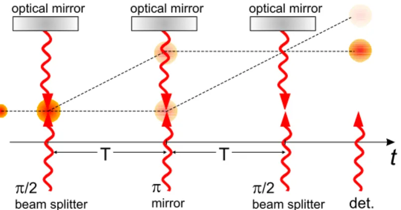
Figure 1.5 shows schematically a common interferometric sequence. The Raman two-photon transition transfers the atom to the other internal ground state and simultaneously changes the momentum of the center-of-mass of the atom’s wave function. This process is coherent and can be performed with any efficiency between 0 and 100% depending on the duration of the Raman pulse. In particular the π2 (π) pulse changes the atomic state with 50% (100%) probability and thus acts as a beam splitter (mirror). A combination of
π
2−π−π2 pulses forms a basic Mach-Zender interferometer. At the end of the sequence the probability to find the atom in one of the states depends on the phase difference ∆φwhich, among other things, depends on the gravitational acceleration g and the square of the time separation T between the Raman pulses:
∆φ= m
~vrecgT2 (1.5)
with the atomic mass m and the photon recoil velocity vrec.
Atom interferometers do not merely demonstrate the wave nature of mat- ter. Due to their unprecedented sensitivity to external forces, they are widely used as inertial sensors in a variety of measurements, whose accuracy is com- parable to, or better than the competing measurements using macroscopic objects. Currently the best known interferometric measurement ofghas been performed with an absolute uncertainty of ∆g/g≈3×10−9 after one minute of integration time and 1×10⁻¹⁰ after two days [Peters et al., 1999, 2001].
The geometry of the cold atoms gravimeter resembles that of the fountain
clock - the atoms are launched vertically - and thus, similar restrictions are put on the maximum height of the setup. Therefore, the interrogation time T is limited by the free fall of the cloud in the vacuum tube. Since the sensitivity of an interferometric measurement scales with the square root of the number of detected particles, low density of the expanding cloud is also a limiting factor. In microgravity T could be easily increased to a few seconds gaining two orders of magnitude in the sensitivity. Nevertheless, it will still be possible to detect the atoms due to much slower expansion of the ultra-cold samples achievable in space.
1.4.3 Benefits for the fundamental research
Two great theories of 20th century, the quantum mechanics and the general relativity, have no common ground: there has been no successful quantiza- tion theory of gravity so far. Almost all modern theories searching for the unification of gravitation with the three other fundamental interaction types, assume violations of Einstein’s equivalence principle (EEP). Some theoretical studies [Lämmerzahl, 2006; Damour and Polyakov, 1994] predict these vio- lations to be in the range 10−13 to 10−21, which could be measurable in the near-future experiments. This motivates for trying to improve the accuracy of various experimental tests of EEP by several orders of magnitude.
EEP, which is a foundation of the general relativity, includes the local position invariance stating that in all local freely falling frames, the outcome of any nongravitational experiment is independent of where and when in the universe it is performed. One consequence of this statement is the time constancy of all nongravitational fundamental constants, such as the fine structure constant α. Another implication is the gravitational redshift of the clock frequency ∆ν/ν0 = ∆U/c2, where c is the vacuum speed of light and
∆U is the difference in Newtonian potential between the actual location of the clock and a reference value for which the clock frequency is ν0. This shift should be independent of the atomic species involved as a reference in the clock. Finally, the local position invariance imposes that all bodies, regardless of their internal composition, fall in the gravity with the same acceleration. This effect, probably the most familiar issue of the EEP, is also known as Einstein’s weak equivalence principle (WEP) or as the equivalence of the inertial and the gravitational mass.
All three above mentioned consequences of the EEP have come under precision tests searching for a tiny deviations from Einstein’s predictions. To give a few examples, the analysis of the Oklo natural nuclear reactor showed that two billion years ago α did not differ from the present value by more than a few parts in 10−7 [Damourb and Dyson, 1996]. A similar upper bound
on a possible fractional time variation of the quantity (µRb/µCs)α−0.44, where µRb,Cs are the magnetic dipole moments of rubidium and cesium respectively, has been measured by comparing the hyperfine frequencies of 133Cs and87Rb using atomic fountain clocks [Marion et al., 2003]. On the other hand, ob- servation of the spectra of distant quasars indicates that α differed in the early universe from the present value by (−7.2±1.8)×10−6 [Webb et al., 2001]. This until now unexplained discrepancy could be further explored with high-precision clocks in space.
Measurements of the gravitational redshift can also benefit from enhanced accuracy of the space clocks. The accuracy of atomic clocks has recently improved to the point at which it has become possible to measure the gravi- tational redshift on Earth over an altitude of one meter. The best up-to-date redshift measurement has been performed in 1976 with an H-maser by the NASA Gravity Probe A rocket [Vessot and Levine, 1979; Vessot et al., 1980].
Predictions of the general relativity have been confirmed at the 2×10⁻⁴ level of accuracy. In another experiment [Bauch and Weyers, 2002] a cesium foun- tain has been compared to an H-maser in a varying gravitational potential caused by the Earth’s annual elliptical motion around the sun. A possible frequency variation of the two standards has been estimated to be less than 2×10⁻⁵∆U/c2.
Since the famous drop attempts of Galileo Galilei in the late 16th century, the weak equivalence principle has been most commonly tested with macro- scopic objects including celestial bodies. Laser lunar ranging [Williams et al., 2004] provides currently the most sensitive test of the WEP with the precision of 3×10⁻¹³. An even more precise test is planed within the STEP mission (Satellite Test of the Equivalence Principle) [Sumner, 2004]. This cryogenic instrument will contain four pairs of macroscopic proof-mass cylinders freely falling inside a satellite. STEP aims at 1 part in 1018 sensitivity.
However, unprecedented precision of atom interferometers will soon lead to laboratory tests of general relativity at levels exceeding those reached by macroscopic bodies and astrophysical observations. One kind of such tests is basing on a comparison of the effect of gravity on macroscopic bodies and on single atoms. So far the most precise measurement of this kind has been performed by A. Peters and S. Chu [Peters et al., 1999, 2001].
The authors measured the difference between the value for g obtained by a falling corner-cube optical interferometer and atomic Cs interferometer to be (7±7)×10−9g. Another sort of experiments deals with microscopic objects only. In an interferometric experiment done by the group of T. W. Hänsch [Fray et al., 2004] the gravitational acceleration of the two isotopes 85Rb and
87Rb was compared, yielding a difference ∆g/g = (1.2±1.7)× 10−7. In the same experiment a free fall measurement of atoms in two different spin
states was performed, giving a result of ∆g/g= (0.4±1.2)×10−7. The most promising experiment of this kind has been recently proposed by the Stanford group of M. Kasevich [Dimopoulos et al., 2007]. With the worldwide highest atom interferometer (H ≈10 m, T = 1.34 s) it should be possible to initially test the equivalence principle to 1 part in 1015 and 1 part in 1017 in the near future. Interferometers in space could further break these limits.
1.5 Existing cold atom platforms in micro- gravity
1.5.1 Experiments in the parabolic flights
The first cold atoms experiment under the condition of reduced gravity is dated to 1993 by Lounis et al. [Lounis et al., 1993]. The authors observed cesium atoms released from a magneto-optical trap and ballisticaly expand- ing for 0.2 s. This simple experiment demonstrated that the fragile optical equipment for the laser cooling can be constructed portable and capable of being used under high-vibration conditions. The free falling reference was provided by a jet plane executing parabolic flights. During such a flight the gravity level is reduced to less than 2 ×10⁻² g for about 20 s. Up to 30 successive parabolas can be made during one flight.
Another French collaboration I.C.E. (Interférométrie Cohérente pour l’Es- pace) aims at the construction of an atom interferometer for inertial sensing in microgravity [et al., 2006a]. A compact and transportable apparatus has been designed to be used during the parabolic flights. A mixture of quantum degenerate gases, bosonic87Rb and fermionic40K will be trapped in a crossed optical dipole trap. Subsequently a series of Raman light pulses will be implemented to form the beam splitters and mirrors for the matter wave interferometer. The I.C.E. interferometer should serve for the acceleration measurements. Currently the lasers and the vacuum system are under tests [et al., 2006a]. Acceleration fluctuations (vibrations) of up to 2×10⁻²g during the parabolic flight have been identified as the main drawback limiting the sensitivity of the interferometer. Therefore implementation of a vibration- isolation system is required.
1.5.2 ACES / PHARAO
ACES: Atomic Clock Ensemble in Space is a project selected by the Euro- pean Space Agency (ESA) to fly on the International Space Station (ISS).
The payload of ACES includes two atomic clocks: a hydrogen maser and a
cold cesium atom clock PHARAO (Projet d’Horloge Atomique à Refroidisse- ment d’Atomes en Orbite). The relative frequency stability of the PHARAO clock on board the ISS is expected to be better than 10−13 for one second measurement time and 3×10⁻¹⁶ for one day. Target accuracy is 10−16.
The goal of the ACES mission is to operate the two kinds of atomic clocks and to make a direct frequency comparison between them on board the ISS.
Moreover, frequency comparison between PHARAO and the ground clocks should be performed with a relative accuracy of 10−16, a factor of 100 better than the best current GPS measurements. These features will give rise to increased precision of some fundamental physics test. The gravitational red- shift, for example, will be measured with a 3×10⁻⁶accuracy. This is a 25-fold improvement compared to the measurement of the Gravity Probe A mission.
Another scientific objectives of ACES include the search for a possible time variation of the fine structure constant as well as an improved test of special relativity. For a review of the ACES mission see reference [et al., 2001].
Concerning the technology readiness for the operation in microgravity, PHARAO is up-to-date the most advanced among the cold atoms projects for space. The satellite version of PHARAO, developed by the French Space Agency (CNES) has entered the industrial development in June 2001. The clock is currently being characterized on the Earth and tested in the reduced gravity environment of the parabolic flights. The details of design and the first test results of the PHARAO clock can be found in reference [et al., 2006b].
1.5.3 QUANTUS
The QUANTUS (Germ.: Quanten Gase unter Schwerelosigkeit) project joined the space-oriented cold atom research community in spring 2004. The mem- bers of the collaboration are the Institutes of Physics from the Universities of Hannover, Ulm, Hamburg, Bremen (ZARM), and the Humboldt University of Berlin, as well as the Max-Planck Institut für Quantenoptik in Garching.
The project is supported by the German Space Agency (DLR) with funds provided by the Federal Ministry of Economics and Technology (BMWi) un- der grant number DLR 50 WM 0346.
Targeting the long-term goal of studying cold quantum gases on a space platform, we currently implemented a 87Rb BEC experiment under micro- gravity condition at the drop tower facility of the Center of Applied Space Technology and Microgravity (ZARM) in Bremen. The Bremen drop tower offers a significant compensation of the Earth gravity down to the 10−6 g level. Duration of microgravity is 4.5 s in the drop-mode and it can be doubled when using the catapult. This time is fairly enough for prelimi-
Figure 1.6: The first BEC realized in mi- crogravity. Absorption image taken after 16 ms TOF. Color scale represents varia- tion in the optical density and the lower graph is integrated optical density along the vertical axis. The condensed part is fitted with an inverted parabola (green) and the residual thermal background with the Gaussian (cyan). From the fit we read N ≈6000 condensed atoms.
nary experiments aiming at the preparation and subsequent observation of the ultra-cold freely falling matter waves. The possible free expansion time of up to 7 seconds represents a gain of factor 100 compared to earthbound experiments.
Within 3 years from the beginning of the project we have designed, built and extensively tested a compact and robust BEC setup suitable for the op- eration in the drop tower. Special challenges in its construction were posed by a low volume of the drop capsule (<1 m3) as well as critical vibrations during capsule release and peak decelerations of up to 50 g during recapture at the bottom of the tower. All mechanical, optical and electronic compo- nents have thus been designed with stringent demands on miniaturization and mechanical stability. Additionally, the system provides remote control capability as it is not manually accessible during the drop. To the best of our knowledge the setup described in chapter 2 is, up-to-date, the only portable BEC apparatus worldwide.
For the sake of chronological completeness, the first laboratory Bose- Einstein condensation with the Quantus drop capsule was realized in Febru- ary 2007. In that year in October we dismounted the setup almost completely and moved from Hannover to Bremen. Just one day after, we were able to reproduce the results from Hannover, which can also be seen as a kind of world record in the speed of a complete rearrangement of an quantum op- tics experiment. This demonstrates the high flexibility and reliability of our hardware.
On 06.11.2007 we succeeded in the first realization of the BEC in micro- gravity (Fig. 1.6). Since that time we have performed over 160 successful
Figure 1.7: Absorption images of the BEC for TOFs 50, 100, 500 and 1000 ms.
drops. The experiment has been optimized to increase the number of atoms in the BEC to roughly 104. The trap steepness has been systematically reduced so that during the last drop campaign we worked with the mean trapping frequency ¯ω = 2π×10.9(±1) Hz. Note that this trapping frequency is not available in any earthbound experiment without levitation. Finally, we increased the time of free evolution to the unprecedented 1 second! (Fig.
1.7). After 1 s the size of the BEC reaches 1 mm with the peak density 3×107 cm−3. By an average expansion speed as low as 1 mm/s, all con- densed atoms are expected to remain within the view field of the camera for 5 s. However, further increasing of the expansion time is currently limited by the low initial number of atoms in the condensate and a poor signal to noise ratio by the detection. The work to reduce the trapping frequencies to the sub-Hz regime is currently in progress.
1.6 Composition of this thesis
The results described in this thesis is an effect of a collaborative effort of the whole QUANTUS team. The author’s contribution to the teamwork includes the design, assembly, characterization and drop tower tests of the complete laser system, including the relevant electronic components. After the com- pletion of all individual components of the experimental setup the author took actively part in their integration into the drop capsule. Afterward he assisted by the most relevant project-milestones, like the generation of the BEC in laboratory, moving the setup to Bremen and operating it at the drop tower, finally by the first realization of the BEC in free fall. Furthermore, cal- culation and characterization of the time dependent trapping potential was done by the author. Simulation of the time evolution of the Boes-Einstein condensate wave function in this potential followed in close cooperation with
the theoretical group in Ulm.
The experimental setup is described in detail in chapter 2. Since the drop tower environment is to a large extent similar to that of a space platform, special emphasis is put on the strict requirements on the experiment to make it drop-tower-qualified.
The central part of the setup is the magnetic micro trap (atom-chip). Its principle of operation, characteristic of generated magnetic field and possible design modifications are the issues of chapter 3.
Chapter 4 contains a complementary, quantitative discussion of the re- sults. It begins with a theoretical treatment of the time dependent evolution of the condensate wave function. An analysis of the time variation of the trapping potential, which drives the evolution of the condensate, follows. Fi- nally, a detailed analysis of the result sketched in figure 1.7 is given in that chapter.
Last, the near future perspective including both further steps with the existing setup and the next generation of the Quantus experiment is briefly illuminated in chapter 5.
Cold atom experiment at the Drop Tower in Bremen
2.1 The drop tower Bremen
The Bremen drop tower is a facility of the Center of Applied Space Technol- ogy and Microgravity (ZARM1) at the University of Bremen. The research is concentrated mainly on the investigation of fluid mechanics phenomena under microgravity conditions and questions related to space technology. Within the scope of QUANTUS, the first quantum physics experiment at ZARM, the properties of a freely falling Bose-Einstein Condensate have been regularly investigated since November 2007.
The tower has a total height of 145 m and provides the possibility to drop experiments inside an evacuated steel drop tube (Fig. 2.1) with an altitude of over 100 m. This allows for approximately 4.7 s free-fall time, which can be doubled if one launches the experiment with a catapult. There are two basic reasons for evacuation of the drop tube. The first is to reduce the air friction during the drop. Second, friction in the deceleration container leads to the accumulation of electrostatic charge on the cover of the capsule. The presence of oxygen could lead to ignition and consequently to a flame. Evacuating the tube takes 2 hours on average and is one of the main factors limiting the repetition rate of the experiment to 3 drops per day. Weightlessness (or zero-g) is only an idealized state that does not exist. In fact any experiment is exposed to residual accelerations: those induced by the mass distribution of the experiment itself, and those caused by the residual vibrations of the experimental apparatus. The residual accelerations (microgravity quality) during the flight are as low as 10−6to 10−5g in the acoustic Fourier frequency
1Germ.: Zentrum für angewandte Raumfahrttechnologie und Mikrogravitation
18
Figure 2.1: Cross-section of the drop tower in Bremen (figure from reference [Dro, 2007]).
range 0-500 Hz (Fig. 2.2). The velocity dependent DC deceleration caused by air friction is of the order of 10−5 g at the end of the flight (measured at the residual pressure in the drop tube of <20 mbar [Sellig, 2007]). This µ-g level is the best one amongst the microgravity facilities and is reached already after 1.5 s after capsule release or after 2 s after catapult launch (for a more detailed analysis of the acceleration in the capsule see theDrop Tower Bremen User Manual [Dro, 2007]).
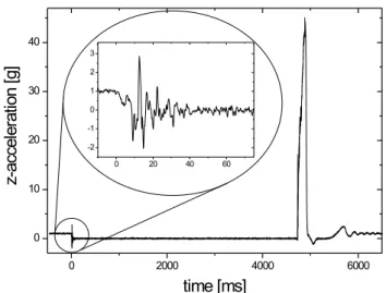
At the bottom of the tower the freely falling drop capsule has a velocity of 166 km/h when it is captured in a deceleration unit. The deceleration container has a height of 5 m and is filled with polystyrene pellets. Despite of the macroscopic (5 mm) diameter of the granulate, the dynamics of the capturing process resembles that of submerging in a viscose fluid. The mea- sured acceleration in vertical direction is shown in figures 2.3 and 2.15. The duration of the impact is 200 ms with an average deceleration value of ap- proximately 25 g. The peak value of the impact deceleration reaches 50 g and
puts one of the most stringent requirements on the mechanical stability of the experimental setup. Note also the residual vibrations at the moment of cap- sule release (at t= 0). The release mechanism has been designed and revised over the years in order to achieve a smooth 1 g - 0 g transition. Nevertheless, the gravitationally induced mechanical tension of the composite elements of the drop capsule is released in microgravity. This excites eigenoscillations of the capsule elements (mainly flat payload platforms) which might affect the stability of the laser system.
Figure 2.2: Time dependent Fourier spectrum of the residual acceleration (microgravity quality) inside of a falling capsule (figure from reference [Dro, 2007]).
Figure 2.3: Acceleration in the z−direction in units of g measured inside of a falling capule
2.2 Requirements on the experiment
The long-term goal of the QUANTUS collaboration is to establish an ex- perimental platform in space to allow the investigation of ultra-cold quan- tum matter in free fall for unlimited time. The drop tower environment is similar to that of a space platform in several aspects. In particular, strict requirements concerning the limited volume, low power consumption, and high mechanical stability of the components have to be fulfilled. Thus, spe- cial technical challenges in the construction of the experimental setup make it different from common earthbound systems to a large extent. In detail, as specified in [Vogel et al., 2006], the following points have been crucial for the design of all mechanical, optical, and electronic modules:
• Miniaturization Optics for a common laboratory BEC experiment usually fills the area of the whole optical table. Roughly the same space above the table is required for the electronics. In contrast, our setup has to fit into the drop capsule, the volume of which is less than one cubic meter (Fig. 2.4 a) ) with a surface of a single payload platform of 0.36 m2 (Fig. 2.4 b) ).
Figure 2.4: a) Two available versions of the drop capsule and b) the payload platform (figures from reference Dro [2007]).
• Low massIn all space missions weight is an important factor in terms of launch costs. The drop capsule can carry a maximum payload of
Table 2.1: Dimensioning of the drop capsules
parameter: \ capsule version: short long catapult
stringer length [mm] 1545 2310 1342
max. payload height [mm] 980 1730 950
total area of experiment-platform [m2] 0.36 0.36 0.36 base structure incl. batteries and computer [kg] 110 110 122.7
top lid plate [kg] 36 36 28.2
vacuum sealed cover incl. clamping rings [kg] 32 54 38.5
4 stringer [kg] 42 60 36.6
nose cone incl. connection rod [kg] 6 6 10.2
1 experiment-platform incl. brackets [kg] 15.2 15.2 15.2
capsule net weight [kg] 226 266 236.2
capsule gross weight [kg] 500 500 400
max. payload mass [kg] 274 234 163.8
234 kg. All masses and dimensions of the drop capsules (including the catapult version) are summarized in table 2.1. Note that more stringent demands on size and weight are put on the catapult capsule.
• Low power consumptionElectrical power for the experiments in the drop tower is supplied from batteries placed at the bottom of the drop capsule. They operate at 28 V DC voltage and can provide a total energy of 0.56 kWh with a peak power of about 3 kW. Obviously, there are even stronger energy constraints on the space platform.
• High mechanical stability Residual vibrations of the platforms at the moment of capsule release can be critical for the laser frequency and light intensity stability. Moreover, all the components used have to withstand the peak deceleration of up to 50 g during impact and catapult launch. Due to the maximal drop rate of three times per day, there is only less than one hour for likely corrections and readjustment of the setup between the flights. Therefore, a permanent misalignment of the experiment after each drop should be avoided. Fulfilling this requirement would also be important in future space missions because of the presence of violent shocks and vibrations during the launch phase.
• Thermal insensitivity Whilst the drop or launch take place in the evacuated drop tube, the capsule is vacuum-tight and there is normal pressure inside of it. Most of the electronics remain turned on during drop tube evacuation, which results in a temperature increase in the
upper parts of the capsule of up to 4 degrees within 2 hours. The com- ponents of the experiment which are highly sensitive to temperature change (e.g. the optical rack with fiber docks) are therefore required to have connection to water cooling circuit.
• Fast BEC preparationIn order to damp the effect of the above men- tioned vibrations, the atoms are kept in the non-conservative magneto- optical trap (MOT) during the capsule release and 1 s thereafter. Thus, all following cooling phases, in particular the evaporation in the mag- netic trap, have to be faster than the total drop time of about 4.7 s minus the free expansion time of up to 1 s.
• Remote control Two hours before the drop, while the drop tube is evacuated, the experiment is accessible only via remote control. In particular, one has to be able to lock the lasers to an adequate atomic transition without manual access.
In the following section the experimental setup will be described in detail, emphasizing how it addresses the above issues.
2.3 Quantus experimental setup
Nowadays Bose-Einstein condensates can be nearly routinely produced in many optical laboratories and a number of different experimental techniques are being extensively discussed in the literature [Metcalf and van der Straten, 1999; Phillips, 1998; Ketterle et al., 1999]. The main requirements are, how- ever, similar. The most important are: good thermal decoupling from the environment using contact-free storage in ultra-high-vacuum chambers (typ- ically better than 10−10 mbar) and a sophisticated two-stage trapping and cooling process. The latter begins with precooling using Doppler- and sub- Doppler laser cooling in a magneto-optical trap down to the temperatures in the µK range. Subsequently, the cold atomic sample is transferred to a conservative trapping potential (magnetic or optical) and cooled further by evaporative cooling.
2.3.1 Drop capsule overview
The QUANTUS drop capsule with its components is depicted in figure 2.5.
The heart of the experiment is the vacuum chamber which houses the mag- netic chip-trap. The uppermost platform is occupied by the complete laser system (including the laser electronic rack) and the remaining space is tightly
Figure 2.5: Quantus drop capsule with its composite modules.
Figure 2.6: Vacuum chamber with magnetic coils and fiber telescopes rigidly attached to the chamber body (left drawing courtesy of Tim van Zoest [van Zoest, 2008]).
filled with control electronics. It is worth to mention that QUANTUS is the heaviest experiment ever dropped at ZARM. The total weight of the drop capsule slightly exceeds the maximal allowed mass of 500 kg.
2.3.2 Vacuum
The atoms are trapped inside of a non-magnetic, stainless steel, ultra high vacuum chamber, which is kept at ultra low pressure of less than 10−10 mbar by an ion getter pump (25 l/s) and a titanium sublimation pump. It is important, that there are no moving elements inside either of the pumps
which could be damaged during deceleration of the capsule. In particular, to avoid long-run loosening, all screws inside of the pumps have been spot- welded. Moreover, high voltage elements of the ion pump are fastened with mounts specially designed for operation in the drop tower, that prevent an eventual short circuit of the electrodes. Also, special attention has been paid to the mounting of the filaments of the titanium pump. These are mounted vertically so that they are less sensitive to torques during capsule deceleration.
To minimize mechanical strains that could lead to leakage, there is only a single suspension of the vacuum chamber inside the drop capsule. All pe- ripheral components like magnetic coils, CCD-camera telescopes and fiber ports are rigidly attached to the steel body of the vacuum chamber, giv- ing maximum stability and minimizing possible sources of relative misalign- ment (Fig. 2.6). A detailed description of the vacuum system, including technical drawings of the chamber and characteristics of the Helmholtz-coils have been given in the PhD thesis of Tim van Zoest [van Zoest, 2008]. A drop tower vacuum-tightness test has been described in reference [Könemann et al., 2007].
2.3.3 Chip trap and mirror MOT
Figure 2.7: a) A common 6-beam MOT and b) 4-beam mirror MOT. The two counter propagating beams perpendicular to the picture plane are not shown. σ+/σ− refer to the light helicity, not the polarization.
In order to meet the need of short evaporation times and low power consumption, we use a magnetic micro-trap on a chip [Reichel et al., 2001;
Folman et al., 2002]. Its operating principle, the architecture of the strip lines as well as the generated magnetic fields are described extensively in chapter 3. At this point it is worth to point out the key role of the chip in magneto-optical trapping and pre-cooling of the atoms before the magnetic
trap is turned on. An ordinary magneto-optical trap consists of 6 orthogo- nal, counter-propagating, circularly polarized laser beams, that intersect at the minimum of a quadrupole magnetic field generated by a pair of macro- scopic anti-Helmholtz coils (Fig. 2.7 a) ). However, this configuration is not applicable in the case of a chip-trap since the chip substrate is not opaque.
Instead, the chip surface features a highly reflective dielectric coating and reflects two of the diagonal beams (Fig. 2.7 b) ). σ+ circularly polarized light changes intoσ−once reflected from a mirror. Therefore in the vicinity of the chip surface, there are pairs of counter-propagating beams with the same helicity but with orthogonal circular polarization seen by the atoms.
The quadrupole field for the MOT can be generated either by the external anti-Helmholtz coils or a superposition of an external bias field and a field that is created from a current through the U-shaped wires on the chip (Chap.
3).
2.3.4 Laser system
Requirements on the laser system
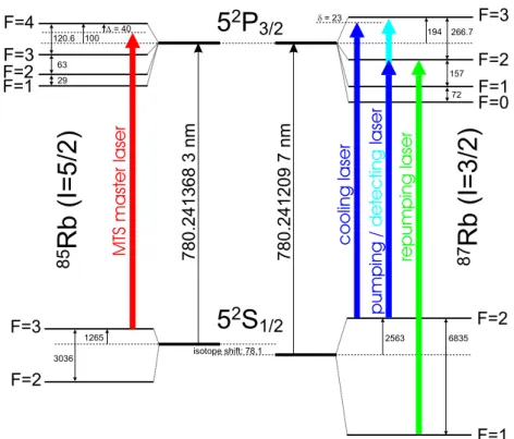
In order to keep the setup as simple as possible, we trap 87Rb, which, like other alkali atoms, has a simple laser cooling scheme (Fig. 2.8) for which laser diodes are commercially available. Furthermore, a relatively high ratio of elastic to inelastic collision rate in 87Rb is advantageous for evaporative cooling.
For cooling and trapping 87Rb atoms in a magneto-optical trap infrared laser light (λ = 780.2 nm) is required to drive the D2 transition 52S1/2 −→
52P3/2. All frequencies used in the experiment can be divided into two classes (blue and green arrows in Fig. 2.8) separated by the hyperfine splitting of the
87Rb ground state (6.8 GHz). For atoms with a natural transition linewidth Γnat, the low intensity theory of Doppler cooling in one dimension yields an optimal detuning of the cooling laser δ that minimizes atomic temperature:
δ =−Γnat/2 [Metcalf and van der Straten, 1999]. In 3D and for light sources with a spectral width comparable to Γnatthe optimal detuning is greater than Γnat/2. Besides, with increased detuning a larger fraction of atoms from the thermal background can be caught. Also the trap volume increases with δ.
Thus, in practice, the optimal detuning δ is of the order of 2-3 Γnat and its value has to be found empirically as a compromise that gives sufficiently low temperature for a still satisfactory number of atoms. In order to fulfill this demand the spectral linewidth of the laser has to be at least as narrow as Γnat (6 MHz for the D2 transition in rubidium) and the long-term frequency variance should be much less than that. As shown in reference [Chen et al.,
Figure 2.8: Hyperfine splitting of the D2 line in rubidium (all frequencies in MHz) and laser transitions (colored arrows) required for the BEC experiment.
2000] the number of trapped 87Rb atoms in a MOT decreases by a factor of 1.7 when the linewidth of the cooling laser approaches 10 MHz.
A total power of about 50 mW of the cooling light is needed at the atom cloud, while a few mW are sufficient for the other transitions.
Full control over laser frequency and intensity at the moment of capsule release and during the flight are critical parameters that determine whether a satisfactory number of atoms can be trapped at a temperature that is low enough to efficiently load the magnetic trap.
Laser system overview
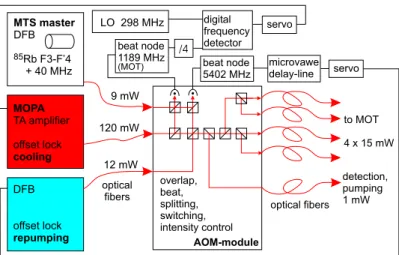
Our laser system is schematically shown in figure 2.9. It consists of a master laser stabilized to an atomic transition, a MOPA amplifier (Master-Oscillator Power Amplifier), a repumping laser (both frequency-offset locked to the master laser), and a power-distribution and -control module with acousto- optic modulators (AOM-module). Optical connections between those mod- ules and with the vacuum chamber are realized exclusively with single mode polarization-maintaining optical fibers.
Figure 2.9: Schematic of the laser system. The red lines are light paths and the black are electronic connections.
All mounts for optical elements have a beam height of 20 mm and were designed by us with a special emphasis on mechanical stability. The majority of them are not adjustable. Exceptions are the mirror holders in front of the fibers (Fig. 2.10 right) and beat photodiodes as well as the mirrors used to superimpose two laser beams. In contrast to most commercially available spring-based adjustable mounts, our ultra-stable stainless steel construction makes use of flexure metal sheets for tilting the mirror.
The laser modules are placed in a stable and robust housing (210×190× 60 mm) made of stress-free aluminum. The three lasers together with the AOM-intensity-control module are integrated into a frame assembly with dimensions chosen to be compatible with a standard 19” electronic rack (Fig.
2.10 left and middle). The laser system including electronics has a total weight of about 45 kg and fits the area of one platform in the drop capsule.
Figure 2.10: Mechanical mount of the laser system. Optic (left) and elec- tronic (middle) racks have the standard width of 19”. Mounts for optics with the beam height of 20 mm (right).
DFB diode
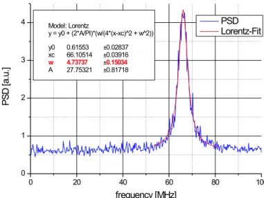
For the sake of mechanical stability, we have intentionally excluded the use of extended cavity diode lasers (ECDL) which are otherwise commonly used for laser trapping. Instead, we drive our laser system with distributed feedback (DFB) laser diodes [Caroll et al., 1998], which have an intrinsic grating in the active semiconductor area. Commercially available DFB diodes from Eagle- yard (EYP-DFB-0780-00080-1500-TOC03-0000) mounted in a TO3 housing with an internal Peltier element fit well our requirements regarding com- pactness. Moreover, the diode’s emission linewidth is about the same or- der of magnitude as the natural linewidth of the 87Rb D2 transition.2. The linewidth was measured by beating the DFB laser with a spectrally much nar- rower (<100 kHz) ECDL laser. The beat signal was subsequently analyzed with three independent methods: fast Fourier transform (FFT), phase-noise analysis and with the use of a spectrum analyzer. An example of the latter is shown in figure 2.11. From the Lorentz fit we obtain a spectral width (FWHM) of 4.7 MHz. The other two methods are described in reference [Schiemangk, 2007] in detail.
Figure 2.11: Power spectral density (PSD) of a DFB diode measured as a beat signal with an ECDL laser. The resolution bandwidth of the spectrum analyzer was 30 kHz and the sweep time 20 ms.
We stabilize the temperature of the diodes, and use only the current to vary the wavelength. DFB diodes have an extremely wide mode-hop-free operation range of more than 100 GHz, which greatly facilitates their use.
2The manufacturer guarantees a linewidth of less than 10 MHz

![Figure 2.1: Cross-section of the drop tower in Bremen (figure from reference [Dro, 2007]).](https://thumb-eu.123doks.com/thumbv2/1library_info/5647784.1693738/29.892.269.620.193.662/figure-cross-section-drop-tower-bremen-figure-reference.webp)
![Figure 2.4: a) Two available versions of the drop capsule and b) the payload platform (figures from reference Dro [2007]).](https://thumb-eu.123doks.com/thumbv2/1library_info/5647784.1693738/31.892.217.680.614.932/figure-available-versions-capsule-payload-platform-figures-reference.webp)
![Figure 2.6: Vacuum chamber with magnetic coils and fiber telescopes rigidly attached to the chamber body (left drawing courtesy of Tim van Zoest [van Zoest, 2008]).](https://thumb-eu.123doks.com/thumbv2/1library_info/5647784.1693738/34.892.183.706.559.746/figure-vacuum-chamber-magnetic-telescopes-rigidly-attached-courtesy.webp)