Tunneling Anomalous and Spin Hall Effects
A. Matos-Abiague1,2 and J. Fabian2
1Department of Physics, University at Buffalo, State University of New York, Buffalo, New York 14260, USA
2Institute for Theoretical Physics, University of Regensburg, 93040 Regensburg, Germany (Received 13 March 2015; revised manuscript received 29 May 2015; published 30 July 2015) We predict, theoretically, the existence of the anomalous Hall effect when a tunneling current flows through a tunnel junction in which only one of the electrodes is magnetic. The interfacial spin-orbit coupling present in the barrier region induces a spin-dependent momentum filtering in the directions perpendicular to the tunneling current, resulting in a skew tunneling even in the absence of impurities. This produces an anomalous Hall conductance and spin Hall currents in the nonmagnetic electrode when a bias voltage is applied across the tunneling heterojunction. If the barrier is composed of a noncentrosymmetric material, the anomalous Hall conductance and spin Hall currents become anisotropic with respect to both the magnetization and crystallographic directions, allowing us to separate this interfacial phenomenon from the bulk anomalous and spin Hall contributions. The proposed effect should be useful for proving and quantifying the interfacial spin-orbit fields in metallic and metal-semiconductor systems.
DOI:10.1103/PhysRevLett.115.056602 PACS numbers: 72.25.Mk, 71.70.Ej, 73.43.Jn, 73.50.Jt
The anomalous Hall effect (AHE) occurs in solids as the result of the interplay between spin-orbit coupling (SOC) and magnetism[1]. Although this fascinating phenomenon has been investigated for more than a century, its complex- ity and rich phenomenology continue to attract the attention of many researchers. The topic has been extensively discussed in various reviews [2–5].
Most of the investigations of the AHE have been focused on the case of lateral transport in magnetic crystals and films. However, recent theoretical investigations explored the possible existence of anomalous Hall currents due to the side-jump and skew-scattering of spin-polarized electrons on impurities located in the insulating barrier of a ferro- magnet-insulator-ferromagnet magnetic tunnel junction (MTJ)[6]. In this Letter we propose an effect which does not rely on scattering on impurities but on the interfacial SOC resulting from the lack of inversion symmetry of the MTJ. The effect can be used for experimentally proving and quantifying the interfacial SOC in metallic and metal- semiconductor systems. This is of particular relevance because the interfacial SOC is crucial for various modern phenomena in solids, e.g., anisotropies in optical [7] and magnetotransport phenomena such as the tunneling aniso- tropic magnetoresistance (TAMR) effect [8–15], as well as for the formation of Majorana fermions in ferromag- netic-atomic-chains–superconductor systems [16]. The interfacial SOC has also been proposed for controlling thermoelectric anisotropies in magnetic[17]and helimag- netic[18]tunnel junctions and for generating SOC-induced spin transfer torque in ferromagnet–normal-metal[19]and in topological-insulator–ferromagnet structures[20].
We show theoretically that, when a current flows through a MTJ with a single ferromagnetic electrode, finite anoma- lous Hall conductances develop in the nonmagnetic
counterelectrode, even in the absence of impurities.
Since this effect originates from the skew tunneling[21]
of the spin polarized carriers through a potential barrier, we refer to it as the tunneling anomalous Hall effect (TAHE).
Similarly, transverse spin currents in the nonmagnetic region originate as a response to a bias applied across the MTJ. Because of its analogy with the spin Hall effect (SHE)[22,23], we refer to this phenomenon emerging in the MTJ as the tunneling spin Hall effect (TSHE).
We consider a MTJ grown in thez∥½001ˆ direction and composed of a ferromagnetic electrode separated by a tunneling barrier from a nonmagnetic counterelectrode (see Fig.1). The tunneling barrier may refer to the presence of an insulator or undoped semiconductor as a spacer between
FIG. 1 (color online). (a) Schematic of a ferromagnet- semiconductor-normal metal tunnel junction. The tunneling current flowing in thezdirection generates the anomalous Hall voltage (VH) in the nonmagnetic electrode. (b) Side view of (a).
Taking the [110] axis as a reference, the magnetization direction (m) and the direction along which the Hall voltage is measured (t) are determined by the anglesφand ϕ, respectively.
the ferromagnetic and normal metal regions or just to a Schotky barrier formed at the interface between a ferro- magnet and an n-doped semiconductor. The model Hamiltonian describing the heterojunction reads as[24],
H¼−ℏ2 2∇ 1
mðzÞ∇þVðzÞ−Δex
2 Θð−zÞm·σþHso: ð1Þ HeremðzÞis thez-dependent effective mass of the carriers, VðzÞ is the potential of the rectangular tunneling barrier, Δex is the exchange energy in the ferromagnet, andΘðzÞis the Heaviside step function, respectively. The components of σ are the Pauli matrices and m¼ ðcosφ;sinφ;0Þ indicates the magnetization direction.
The lack of inversion symmetry of the structure induces a Bychkov-Rashba (BR) SOC [25]. If the material forming the barrier exhibits bulk inversion asymmetry, an additional contribution of Dresselhaus (D) type appears in the SOC [26]. To capture these effects, we include in Eq. (1) the effective SOC Hamiltonian, Hso¼HRþHD, where,
HR¼αðkyσx−kxσyÞδðzÞ; ð2Þ is the interfacial BR SOC [27,28],
HD¼−ðkyσxþkxσyÞ∂zγ∂z; ð3Þ contains both the bulk-like and interfacial D SOCs[24,27], andδðzÞis the Dirac-delta function. The D parameterγ is piecewise constant, being finite in the semiconducting barrier and zero elsewhere.
The wave function of the system can be written as ΨjiσðrÞ ¼eik∥·r∥ΦjiσðzÞ= ffiffiffiffiffi
Az
p ; ð4Þ
where Az is the transverse area and ΦjiσðzÞ represent the scattering states propagating along the z direction. The subindexi¼l; c; r labels the region (left, center, or right) andσ¼↑;↓refers to the spin of the incident particle. The superindex (j¼l; r) indicates whether the particle comes from the left (ferromagnetic electrode) and propagates to the right (nonmagnetic electrode) or vice versa. The scattering states, ΦjiσðzÞ, can be computed in a similar way as in Refs. [24,27].
The charge current density flowing along the transverse direction η (η¼x; y) in the nonmagnetic electrode is determined by [29]
Jη¼X
σ
ðJl→rησ þJr→lησ Þ; ð5Þ
where Ji→jησ denotes the current contribution of the spin-σ modes propagating from the ith to thejth electrode. Note that since the interfacial SOC is only present in the barrier region, the velocity operator in the nonmagnetic electrode is simply given by vη¼pη=m¼−ðiℏ=mÞ∂η.
For low temperatures and small bias voltage,Vz, taking the Fermi energy as the zero of the energy scale, the conductance,Gηz¼Iη=Vz, reduces to[29],
Gηz¼− AηG0
2ð2πÞ2 X
σ
Z dk∥kη
jtσσj2þ jtσ;−σj2 kσ
E¼0; ð6Þ where Aη is the cross sectional area through which the current Iη¼JηAη flows, G0¼2e2=h is the quantum of conductance, kσ ¼ ffiffiffiffiffiffiffiffiffiffiffiffiffiffiffiffiffi
k2Fσ−k2∥ q
, and κ¼ ffiffiffiffiffiffiffiffiffiffiffiffiffiffiffi κ2F−k2∥ q
are, respectively, the wave vector components in the ferromag- netic and nonmagnetic electrodes at the Fermi energy,kFσ
denotes the Fermi wave vector corresponding to the spinσ channel in the ferromagnet, andκFis the Fermi wave vector of the nonmagnetic electrode. The coefficient tσ;σ (tσ;−σ) depends on the interfacial SOC [29] and describes the process of an incident spin-σ particle being transmitted with conserved (flipped) spin orientation. The tunneling (Gzz) and TAHE conductances (Gxz and Gyz) can be computed by using Eq.(6).
The current and voltages in the nonmagnetic electrode are related asIη¼GημVμ. The lack of magnetism in this region of the heterostructure implies thatGxy¼Gyx¼0.
Furthermore, assuming a cubic material for the nonmag- netic electrode yields Gxx¼Gyy¼G⊥. The resistances Rημcan be found by inverting the conductance. Under open circuit conditions in the x and y directions (i.e., Ix ¼Iy¼0) and taking into account that the diagonal components of the conductance are much larger than the off-diagonal ones, we obtain the following approximate relations for the TAHE resistances and voltages[29]:
Rηz≈Gηz=ðG⊥GzzÞ; Vη≈ −GηzVz=G⊥; ð7Þ withη¼x; y. In what follows we consider, for the sake of simplicity, a sample with equal tunneling and Hall contact areas (i.e.,Ax ¼Ay ¼Az¼A).
For illustration we performed numerical calculations for an Fe/GaAs/Au tunnel junction with the same system parameters as in Refs. [9,24,27]. Two different values of the BR parameter,α¼−0.6eV Å2andα¼−17.4eV Å2 were considered. These values were extracted from the experimental data of the TAMR measured in an Fe/GaAs/
Au tunnel junction at bias voltages of 50 mV and 90 mV, respectively [9].
The results are shown in Fig. 2, where the TAHE conductance ratios Gxz=Gzz and Gyz=Gzz along the x∥½110 and y∥½¯110 axes, respectively, are displayed as functions of the magnetization direction. The tunneling Hall conductance Gxz (Gyz) exhibits a sine-type (cosine- type) dependence on the magnetization orientation indicat- ing that the TAHE is of first order in the SOC strength. This contrasts with the TAMR effect, which is of second order in
SOC[24,30]. The small values of the TAMR (less than 1%) measured in Fe/GaAs/Au MTJs [9] indicate that the anisotropic contribution to the tunneling conductance Gzzcan be neglected. In fact the cosð2φÞ-type dependence of Gzz is so small that it cannot be seen on the scale of Fig. 2. The magnetization orientation dependence of the TAHE conductances is a manifestation of the magneto- anisotropic effects while the different amplitudes of Gxz and Gyz reflect the crystalline magnetoanisotropy of the system.
We can estimate the amplitudes of the TAHE resistances by using Eq. (7). The conductance G⊥ describes the response of the gold region to an applied transverse voltage and is not related to tunneling. It can therefore be estimated asG⊥¼σAuA=L, whereσAu ¼4.1×10⁵Ω−1cm−1is the conductivity of gold at room temperature. Assuming a lateral size L¼10μm and taking into account that the amplitudes of bothGxz=GzzandGyz=Gzzare of the order of 10−3 (see Fig. 2) we obtain TAHE resistances of about 2.5μΩ and TAHE voltages of 0.25 nV for a typical tunneling current of the order of 100μA.
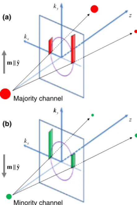
In order to get more insight on the physical origin of the TAHE, it is convenient to analyze the limit case of a very thin barrier. In such a case the barrier potential together with the SOC can be interpreted as an effective, spin and momentum-dependent potential, i.e., Veff¼hδðzÞ, where the height of the effective barrier is given by,
h¼V0dþ ðw·σÞ ¼V0dþ ðα−βÞkyσx−ðαþβÞkxσy; ð8Þ whereβrepresents the effective parameter of the linearized D SOC. One can see from Eq.(8)that the SOC affects the tunneling by modifying the height (h) of the effective barrier according to the in-plane momentum and spin orientation of the incident particle. This, together with the existence of spin polarization in the ferromagnetic lead, creates an imbalance between transmitted particles with in- plane momenta −k∥ and k∥ and results in finite TAHE currents in the nonmagnetic counterelectrode. The spin- dependent momentum filtering is schematically shown in Fig.3, where, for the sake of simplicity, we consider the tunneling of particles with ky ¼0 through a barrier with BR SOC only. This mechanism resembles the conventional skew scattering of spin polarized carriers on impurities [21]. However, unlike the conventional skew scattering, the tunneling skew scattering does not depend on the transport lifetime [31]. By situating the transverse Hall contacts within a distance from the barrier smaller than the electron mean free path (a few hundred nanometers for metals such as Cu, Au, Al at low temperature[32]), the TAHE offers a unique opportunity for the experimental investigation of the intrinsic character of the tunneling skew scattering [33].
The strength of the Dirac-delta barrier can be charac- terized by the parameter Q¼2m0V0d=ℏ2. In the
high-barrier limit Q dominates over the Fermi momenta (i.e., Q≫kFσ and Q≫κF) and over the SOC at the Fermi wave vectors (i.e., Q≫2m0jwðkFσÞj=ℏ2 and Q≫2m0jwðκFÞj=ℏ2). In such a limit the Hall conductan- ces can be approximated by the following analytical expressions:
Gηz≈∓2G0
π
Aðk5F↑−k5F↓Þ
15Q3 ðλαλβÞ sinφ
cosφ; ð9Þ withη¼x; y. In the equation above we have introduced the dimensionless SOC parameters, λα ¼2m0α=ℏ2 and λβ¼2m0β=ℏ2.
From Eq. (9) one can conclude that, as in the conven- tional AHE, the TAHE conductance vanishes in the absence of spin polarization (i.e., whenkF↑¼kF↓). Furthermore, these simplified analytical expressions properly describe the magnetization orientation dependence of the numeri- cally calculated TAHE conductances (see Fig.2).
According to Eq. (9), the TAHE conductance along the in-plane direction t¼ ðcosϕ;sinϕ;0Þ (see Fig. 1) is given by,
Gtz≈2G0
π
Aðk5F↑−k5F↓Þ
15Q3 ½λαsinðϕ−φÞ−λβsinðϕþφÞ:
ð10Þ The BR SOC does not contain information about the orientation of the in-plane crystallographic axes, since it is invariant under rotations around the [001] axis.
Consequently, in the absence of the D SOC (i.e., when λβ¼0), the TAHE conductance exhibits a magnetoaniso- tropic behavior, i.e., it depends on both the direction along which it is measured and the magnetization direction but only through their relative angle,ϕ−φ[see Eq.(10)].
0° 90° 180° 270° 360°
-1x10⁻³ -5x10⁻⁴ 0 5x10⁻⁴ 1x10⁻³
0° 90° 180° 270° 360°
-1x10⁻³ -5x10⁻⁴ 0 5x10⁻⁴ 1x10⁻³
0° 90° 180° 270° 360°
-1x10⁻³ -5x10⁻⁴ 0 5x10⁻⁴ 1x10⁻³
0° 90° 180° 270° 360°
-2x10⁻³ -1x10⁻³ 0 1x10⁻³ 2x10⁻³
d = 4 nm d = 8 nm d = 16 nm
(c) Gxz / Gzz
ϕ (a)
α = -0.6 eVÅ2 d = 4 nm d = 8 nm d = 16 nm α = -0.6 eVÅ2
Gyz / Gzz
ϕ d = 4 nm
d = 8 nm d = 16 nm
(d) Gxz / Gzz
ϕ
(b)
α = -17.4 eVÅ2 d = 4 nm d = 8 nm d = 16 nm α = -17.4 eVÅ2
Gyz / Gzz
ϕ
FIG. 2 (color online). Dependence of the TAHE conductance ratios,Gxz=Gzz[(a), (c)] andGyz=Gzz[(b), (d)], on the magneti- zation direction for different values of the BR parameter (α) and barrier thickness (d).
Unlike the BR, the D SOC is not invariant under rotations around the [001] axis. Therefore, when λβ≠0, the TAHE conductance acquires a crystalline magneto- anisotropic character; i.e., it depends on both the magneti- zation orientation and the crystallographic direction along which it is measured. In contrast to the conventional isotropic AHE conductance, the TAHE conductance mea- sured along the magnetization direction (i.e., whenϕ¼φ) remains, in general, finite. This is a peculiar signature of the crystalline magnetoanisotropy induced by the D SOC.
By aligning the magnetization along the [010] direction (i.e.,φ¼π=4) and combining Eqs.(7)and(9)one obtains
λα
λβ¼Gxz−Gyz
GxzþGyz¼Vx−Vy
VxþVy: ð11Þ Thus, the measurement of the TAHE voltages Vx andVy
could be used as a tool for the experimental determination
of the ratio α=β, which although previously measured in quantum wells [34] and quantum wires [35] has not yet been measured in tunneling systems.
Apart from the TAHE, the spin-dependent momentum filtering also generates a transverse spin current in the nonmagnetic electrode. The tunneling spin Hall current (in units ofℏ=2e) corresponding to the spin component along the magnetization direction (m) and propagating in the nonmagnetic electrode along theη direction is given by
Jmη ¼X
σ
σðJlησþJrησÞ: ð12Þ
The calculation of the tunneling spin Hall and TAHE currents is quite similar and we omit further computational details.
The tunneling spin Hall currents computed with the square-barrier model exhibit the same angular dependences as the AHE conductances (see Fig.2) but with amplitudes varying from few A=cm2 for an 8 nm thick barrier to 104 A=cm2 for d¼4nm. In the limit of a Dirac-delta barrier, the following approximate expressions for the spin Hall currents were found:
Jmη ≈∓2G0V π
ðk5F↑þk5F↓Þ
15Q3 ðλαλβÞ sinφ
cosφ; ð13Þ whereη¼x; y. From the equations above, one can see that unlike the AHE conductances, the spin Hall currents remain finite even in the absence of magnetization (i.e., whenkF↑¼kF↓).
Note that in our analysis we have not considered the effect of the atomic SOC present in the nonmagnetic electrode. While it should not play a significant role for the TAHE (there is no magnetization in the nonmagnetic electrode), it may produce additional contributions to the TSHE due to conventional SHE. Thus, the use of a nonmagnetic electrode with small SOC would be exper- imentally preferred for the measurement of the TSHE.
Nevertheless, even if both the TSHE and SHE are present, their contributions can be experimentally distinguished by using their different scaling with system parameters or by analyzing the anisotropy of the signal with respect to different, transverse crystallographic directions.
In summary, we have theoretically shown that the presence of interfacial SOC in tunnel junctions produces an imbalanced spin-dependent momentum filtering in the directions perpendicular to the tunneling current when one of the electrodes is magnetic. As a result both anomalous Hall voltages and spin Hall currents develop in the other electrode even when within its region, magnetism, impurities, and SOC are absent. This proposed phenome- non should also be important to prove and quantify the interfacial spin-orbit fields in metallic and metal-
ky
kx
y m ˆ
Majority channel (a)
k (b)
ky
kx
y m ˆ
Minority channel
FIG. 3 (color online). Spin-dependent momentum filtering resulting from tunneling through a barrier with BR SOC characterized by the parameterα>0. Particles propagate from the ferromagnetic (left) electrode into the nonmagnetic (right) region. For ky¼0 and m∥y the height of the effective, spin- dependent potential barrier ish¼V0d−σαkx[see Eq.(8)] with σ¼1 (σ¼−1) for an incident particle with spin parallel (antiparallel) to the magnetization. Therefore, for the majority channel (σ¼1) the transmission of particles with kx>0 is favored, as schematically shown in (a). The momentum imbal- ance in the transmitted states generates a transverse current. For the minority channel (b) the situation is opposite. However, due to the presence of spin polarization, the contribution of the majority channel dominates. The result is a finite TAHE current in the x direction, Jx<0 (and a finite TAHE conductance, Gxz¼JxAx=Vz). The situation for α<0 is analogue but the TAHE current flow is reversed, i.e.,Jx>0.
semiconductor systems which are vital to many modern phenomena in solids.
This work has been supported by the DFG (SFB 689) and US DOE-BES Grant No. DE-SC0004890.
[1] I.Žutić, J. Fabian, and S. D. Sarma,Rev. Mod. Phys. 76, 323 (2004).
[2] P. Wölfle and K. Muttalib, Ann. Phys. (Leipzig) 15, 508 (2006).
[3] N. Nagaosa, J. Phys. Soc. Jpn.75, 042001 (2006).
[4] N. A. Sinitsyn,J. Phys. Condens. Matter20, 023201 (2008).
[5] N. Nagaosa, J. Sinova, S. Onoda, A. H. MacDonald, and N.
P. Ong,Rev. Mod. Phys.82, 1539 (2010).
[6] A. Vedyayev, N. Ryzhanova, N. Strelkov, and B. Dieny, Phys. Rev. Lett. 110, 247204 (2013); A. V. Vedyayev, M. S. Titova, N. V. Ryzhanova, M. Y. Zhuravlev, and E. Y. Tsymbal,Appl. Phys. Lett.103, 032406 (2013).
[7] S. Putz, M. Gmitra, and J. Fabian,Phys. Rev. B90, 045315 (2014).
[8] C. Gould, C. Rüster, T. Jungwirth, E. Girgis, G. M. Schott, R. Giraud, K. Brunner, G. Schmidt, and L. W. Molenkamp, Phys. Rev. Lett.93, 117203 (2004).
[9] J. Moser, A. Matos-Abiague, D. Schuh, W. Wegscheider, J.
Fabian, and D. Weiss,Phys. Rev. Lett.99, 056601 (2007);
M. Wimmer, M. Lobenhofer, J. Moser, A. Matos-Abiague, D. Schuh, W. Wegscheider, J. Fabian, K. Richter, and D.
Weiss,Phys. Rev. B80, 121301 (2009).
[10] T. Uemura, M. Harada, K.-i. Matsuda, and M. Yamamoto, Appl. Phys. Lett.96, 252106 (2010); T. Akiho, T. Uemura, M. Harada, K.-i. Matsuda, and M. Yamamoto,Appl. Phys.
Lett.98, 232109 (2011).
[11] S. Sharma, S. P. Dash, H. Saito, S. Yuasa, B. J. van Wees, and R. Jansen,Phys. Rev. B86, 165308 (2012).
[12] K. von Bergmann, M. Menzel, D. Serrate, Y. Yoshida, S.
Schröder, P. Ferriani, A. Kubetzka, R. Wiesendanger, and S. Heinze,Phys. Rev. B86, 134422 (2012).
[13] M. Tran, J. Peiro, H. Jaffrès, J.-M. George, O. Mauguin, L.
Largeau, and A. Lemaître, Appl. Phys. Lett. 95, 172101 (2009).
[14] N. Néel, S. Schröder, N. Ruppelt, P. Ferriani, J. Kröger, R.
Berndt, and S. Heinze,Phys. Rev. Lett.110, 037202 (2013).
[15] K. Wang, J. G. M. Sanderink, T. Bolhuis, W. G. van der Wiel, and M. P. de Jong,Phys. Rev. B89, 174419 (2014).
[16] S. Nadj-Perge, I. K. Drozdov, J. Li, H. Chen, S. Jeon, J. Seo, A. H. MacDonald, B. A. Bernevig, and A. Yazdani,Science 346, 602 (2014).
[17] C. López-Monís, A. Matos-Abiague, and J. Fabian,Phys.
Rev. B90, 174426 (2014).
[18] C. Jia and J. Berakdar, Appl. Phys. Lett. 98, 192111 (2011).
[19] A. Manchon,Phys. Rev. B83, 172403 (2011).
[20] F. Mahfouzi, N. Nagaosa, and B. K. Nikolić, Phys. Rev.
Lett.109, 166602 (2012).
[21] To differentiate it from the conventional skew scattering on impurities we refer to the scattering of spin polarized carriers on the tunneling barrier as skew tunneling. Both skew scattering and skew tunneling originate from the presence of asymmetric chiral contributions to the transition (transmission in the case of tunneling) probability. The asymmetry in the skew scattering is caused by the SOC of impurities while the skew tunneling originates from the interfacial SOC at the tunneling barrier.
[22] M. I. D’yakonov and V. I. Perel, Sov. Phys. JETP Lett.13, 467 (1971).
[23] J. E. Hirsch,Phys. Rev. Lett.83, 1834 (1999).
[24] A. Matos-Abiague and J. Fabian,Phys. Rev. B79, 155303 (2009).
[25] Y. A. Bychkov and E. I. Rashba, JETP Lett. 39, 78 (1984).
[26] G. Dresselhaus,Phys. Rev.100, 580 (1955).
[27] J. Fabian, A. Matos-Abiague, C. Ertler, P. Stano, and I.
Žutić,Acta Phys. Slovaca57, 565 (2007).
[28] M. Gmitra, A. Matos-Abiague, C. Draxl, and J. Fabian, Phys. Rev. Lett.111, 036603 (2013).
[29] See Supplemental Material at http://link.aps.org/
supplemental/10.1103/PhysRevLett.115.056602 for more details.
[30] A. Matos-Abiague, M. Gmitra, and J. Fabian,Phys. Rev. B 80, 045312 (2009).
[31] From this point of view the skew tunneling behaves like the so-called intrinsic skew scattering [4], a mechanism that because of its independence on the transport lifetime is sometimes absorbed into the side-jump contributions to the AHE[5]. Note, however, that theintrinsicpart of the skew scattering originates from the presence of impurities in the ferromagnetic electrode while skew tunneling does not rely on impurities but on the interfacial SOC at the tunneling barrier.
[32] N. W. Ashcroft and N. D. Mermin, Solid State Physics, Science: Physics (Saunders College, Philadelphia, 1976).
[33] For an optimal experimental sensitivity the length of the Hall contacts in the zdirection must also be of the same order or smaller than the carrier mean free path.
[34] S. D. Ganichev, V. V. Bel’kov, L. E. Golub, E. L. Ivchenko, P. Schneider, S. Giglberger, J. Eroms, J. De Boeck, G.
Borghs, W. Wegscheider, D. Weiss, and W. Prettl, Phys.
Rev. Lett.92, 256601 (2004).
[35] M. Scheid, M. Kohda, Y. Kunihashi, K. Richter, and J. Nitta, Phys. Rev. Lett.101, 266401 (2008).