Research Collection
Monograph
On the variability of squeezing behaviour in tunnelling
Author(s):
Mezger, Florence Publication Date:
2020-04
Permanent Link:
https://doi.org/10.3929/ethz-b-000424080
Rights / License:
In Copyright - Non-Commercial Use Permitted
This page was generated automatically upon download from the ETH Zurich Research Collection. For more information please consult the Terms of use.
ETH Library
IGOn the variability of squeezing behaviour in tunnellingFlorence Mezger
ISBN: 978-3-7281-4005-0
Band 254 06/2020
On the variability of squeezing behaviour in tunnelling
Florence Mezger
Weitere aktuelle vdf-Publikationen finden Sie in unserem Webshop:
vdf.ch
Gerne informieren wir Sie regelmässig per E-Mail über unsere Neuerscheinungen.
@vdfVerlagETHZ vdf.hochschulverlag.eth.zurich
› Bauwesen
› Naturwissenschaften, Umwelt und Technik › Informatik, Wirtschafts-
informatik und Mathe matik
› Wirtschaft
› Geistes- und Sozialwissen- schaften, Inter disziplinäres, Militärwissenschaft,
Politik, Recht
Newsletter abonnieren
Anmeldung auf vdf.ch
On the variability of squeezing behaviour in tunnelling
Florence Mezger
Veröffentlichungen des Instituts für Geotechnik (IGT) der ETH Zürich Band 254, April 2020
vdf Hochschulverlag AG an der ETH Zürich
Weitere aktuelle vdf-Publikationen finden Sie in unserem Webshop:
vdf.ch
Gerne informieren wir Sie regelmässig per E-Mail über unsere Neuerscheinungen.
› Bauwesen
› Naturwissenschaften, Umwelt und Technik › Informatik, Wirtschafts-
informatik und Mathe matik
› Wirtschaft
› Geistes- und Sozialwissen- schaften, Inter disziplinäres, Militärwissenschaft,
Politik, Recht
Newsletter abonnieren
Anmeldung auf vdf.ch
Bibliografische Information der Deutschen Nationalbibliothek Die Deutsche Nationalbibliothek verzeichnet diese Publikation in der Deutschen Nationalbibliografie; detaillierte bibliografische Daten sind im Internet über http://dnb.d-nb.de abrufbar.
ISBN: 978-3-7281-4005-0 (Printversion) ISBN: 978-3-7281-4006-7 (E-Book)
Bei Tunnelvortrieben durch druckhaftes Gebirge stellt man oft eine wechselhafte Intensität der Gebirgsverformungen fest und dies trotz gleichbleibender Ausbruchsicherung, gleicher Überlagerungshöhe und vordergründig gleichbleibender Gebirgsbeschaffenheit. Die Varia- bilität der Druckhaftigkeit erschwert Voraussagen über das Gebirgsverhalten während des Vortriebs. Sie ist eine der Hauptursachen für Rückschläge, die selbst bei erfahrenen Inge- nieuren vorkommen können.
Bei gegebener Überlagerungshöhe und Ausbruchsicherung hängen die Gebirgsverformun- gen bekanntlich von den mechanischen Eigenschaften des Gebirges, von der Raumstellung allfälliger Schichtungs- oder Schieferungsebenen sowie von der Grösse des Porenwasser- drucks ab. Es ist daher naheliegend, dass die Gründe einer Variabilität der Druckhaftigkeit während des Vortriebs in einer Wechselhaftigkeit dieser Einflussfaktoren längs des Tunnels liegen müssen. Allerdings ist nicht bekannt, in welchem Masse diese Faktoren das Ge- birgsverhalten beeinflussen und wie sie bei tunnelstatischen Berechnungen berücksichtigt werden können, wenn sie sich innert kurzen Abständen längs des Tunnels ändern, wie dies bei einer Wechsellagerung von schwächeren und festeren Gesteinen oder bei einem intensiv gefalteten Gebirge der Fall ist. Ferner muss ein heterogener Gebirgsaufbau nicht zwangs- läufig zu einer wechselhaften Intensität der Gebirgsverformungen führen. Eine im Vergleich zum Tunnelradius kleinmassstäbliche Variation der Gesteinseigenschaften dürfte sich kaum durch wechselhafte Konvergenzen beim Vortrieb bemerkbar machen; dabei ist allerdings unbekannt, (a), wie eng die Wechsellagerung von weichen und harten Gesteinen sein muss, damit das Gebirgsverhalten makroskopisch homogen erscheint und, (b), wie man reprä- sentative, für tunnelstatische Berechnungen adäquate Gebirgsparameter anhand der Eigen- schaften und der Anteile der verschiedenen Gesteine bestimmen soll.
Mit diesen wissenschaftlich anspruchsvollen und für die Tunnelbaupraxis relevanten Fragen setzt sich diese Dissertationsschrift auseinander. Frau Mezger hat die Erfahrungen aus den druckhaften Strecken der drei Alptransit-Basistunnel ausgewertet; eine Reihe von geotech- nisch-geologischen Situationen quantitativ untersucht; beim Schildvortrieb (der bekanntlich sehr empfindlich auf wechselhafte Gebirgsverformungen bzw. Gebirgsdrücke reagiert) ver- schiedene Ausbauoptionen systematisch analysiert und basierend auf ihren Untersuchungen nützliche Hilfsmittel und Hinweise für die Projektierung ausgearbeitet.
Prof. Dr. G. Anagnostou
Acknowledgements
I wish to express my sincerest gratitude to my supervisor Prof. Dr. Georg Anagnostou (ETH Zurich) for his guidance, encouragement and support during the last years and thank him for the opportunity to work together with him on challenging research and consulting projects.
I am also deeply grateful to Prof. Dr. Frédéric L. Pellet (MINES ParisTech) for agreeing to be co-examiner of this doctoral thesis. His constructive comments were of great value.
This doctoral thesis evolved within the framework of the research projects “On the variability of squeezing behaviour in tunnelling” and “Einsatzgrenzen von Tübbingausbauten in druck- haftem Gebirge”, respectively. The support given by the Federal Road Office of Switzerland (FEDRO) as well as the Commission for Technology and Innovation (a promotional agency of the Swiss confederation) is greatly appreciated.
Furthermore, I would like to acknowledge the AlpTransit Gotthard AG (Switzerland) and BLS AlpTransit AG (Switzerland) for their permission to use data from the construction of the Gotthard, Ceneri and Lötschberg Base Tunnel for this doctoral thesis. Special thanks go to all those involved, who allowed access to the documents and monitoring data needed for this research, particularly to Stefano Morandi (Pini Swiss Engineers), Reto Wagner (Kellerhals + Haefeli AG), Hans-Ulrich Riesen (ristag Ingenieure AG), Dr. Stefan Irngartinger and Peter Teuscher (BLS Netz AG – Alptransit, Switzerland). I would also like to express my gratitude to Werner Burger (Herrenknecht AG) for his comments and suggestions concerning TBM technology and construction process, Flavio Chiaverio (Aegerter & Bosshardt AG) for his ideas about a double shell lining with an inner ring made of cast in-situ concrete, Prof. Fritz Grübl (Hochschule für Technik Stuttgart, PSP Consulting Engineers GmbH) for his inputs on high or ultra-high performance concretes and Dr. Eike Klingsch (ETH Zurich) for discussions about the fire resistance of high or ultra-high performance concretes.
Furthermore, I express my warmest thanks to all my colleagues I have collaborated with during the years at the ETH Zurich for all the interesting discussions, the support and especially the pleasant working atmosphere.
Last but not least, I owe my deepest thanks to my family and friends – especially to Stefan, to my sister Isabelle and to my parents Anne-Chantal and Anton Christian – for their continuous understanding, support and encouragement.
Florence Mezger Zurich, May 2019
Summary
The magnitude of squeezing deformations in tunnelling often varies over short distances, even if there is no obvious change in the construction method, in the depth of cover, in the lithology or rock structure. As long as the reasons for the variability are not known, the tunnelling-induced convergences cannot be predicted with sufficient reliability. Reliable predictions, however, are important for determining the temporary support or the excavation diameter. Otherwise, large-scale tunnel repairs may be necessary, which can cause delay and additional costs due to remedial actions as well as due to the enforced interruption of other operations in progress at the same time.
The analysis of different case studies concerning the AlpTransit project shows that the squeezing variability can be traced back to the heterogeneities in the rock mass at different scales as well as the variation of the orientation of the planes of anisotropy (bedding or schistosity) to the tunnel axis.
In order to improve safety and economy of tunnel construction in squeezing ground, the influence of these factors on the convergences was determined quantitatively (by means of analytical solutions or numerical modelling), so that they can be used as indicators during construction for the timely identification and prediction of the squeezing behaviour. Particular attention was paid on factors whose variation, even if small, may affect the convergences sensitively. Based on these quantitative investigations, design aids were developed, which should help the project engineer to estimate and better understand the variability of the squeezing intensity.
The squeezing variability also concerns TBM tunnelling: In contrast to conventional tun- nelling, shielded TBMs are particularly vulnerable to squeezing due to the very limited space available. Therefore, in order to better deal with the squeezing variability in TBM tunnelling, different (stiff as well as deformable) lining options were discussed.
Keywords: tunnelling; squeezing; schistosity; heterogeneity; analytical solution; numerical modelling; segmental lining.
Zusammenfassung
Die Intensität der Gebirgsverformung bei einer druckhaften Strecke ist in der Regel stark veränderlich. Trotz gleichbleibender Ausbruchsicherung, gleicher Überlagerungshöhe und derselben lithologischen Einheit lassen sich häufig sprunghafte Änderungen der Kon- vergenzen auf kurzer Distanz feststellen. So lange die Gründe für diese Variabilität nicht bekannt sind, sind zuverlässige Voraussagen des Gebirgsverhaltens nach dem Tunnel- ausbruch schwierig. Zuverlässige Voraussagen sind aber wichtig, um die Sicherungsmittel und den Ausbruchsquerschnitt zu bestimmen und damit kostspielige und aufwändige Nach- profilierungsarbeiten zu vermeiden.
Die Analyse von ausgewählten Vortrieben des AlpTransit-Projektes zeigt, dass die Varia- bilität der Druckhaftigkeit auf die Heterogenität des Gebirges in verschiedenen Massstäben sowie auf die variierende Orientierung der Trennflächen (Schieferung, Schichtung) in Bezug zur Tunnelachse zurückgeführt werden kann.
Um die Sicherheit und Wirtschaftlichkeit beim Tunnelbau in druckhaftem Gebirge zu steigern, wurde der Einfluss dieser Faktoren auf die Konvergenzen quantitativ (mittels analytischer Lösungen oder numerischer Berechnungen) ermittelt, so dass diese als Indikatoren für die rechtzeitige Identifikation und Vorhersage des druckhaften Verhaltens genützt werden kön- nen. Besondere Beachtung wurden Faktoren geschenkt, deren kleine Veränderung einen starken Einfluss auf die Intensität der Konvergenzen haben. Basierend auf diesen quanti- tativen Untersuchungen wurden Entscheidungshilfen entwickelt, welche dem projektierenden Ingenieur helfen sollen, die Variabilität der Druckhaftigkeit zu beurteilen und besser zu erfassen.
Die Variabilität der Druckhaftigkeit betrifft auch den Vortrieb mit einer TBM: Im Gegensatz zum konventionellen Vortrieb, sind Einfachschild-TBMs besonders anfällig für Druck- haftigkeit. Um die Variabilität der Druckhaftigkeit bei einem TBM-Vortrieb besser beherrschen zu können, wurden deshalb verschiedene (steife wie auch verformbare) Ausbausysteme diskutiert.
Stichwörter: Tunnelbau; Druckhaftigkeit; Schieferung; Heterogenität; analytische Lösung;
numerische Modellierung; Tübbingsysteme.
Contents
Vorwort ... iii
Acknowledgements ... v
Summary ... vii
Zusammenfassung ... ix
Contents ... xi
Introduction ... 1
Problem statement ... 1
Structure of the thesis ... 2
Remarks ... 7
Publications ... 7
PART I: ANALYSIS OF CASE HISTORIES ... 9
1 Sedrun Section of the Gotthard Base Tunnel ... 11
1.1 Introduction ... 11
1.2 Geology ... 13
1.3 Construction Method... 21
1.4 Rock response to tunnelling ... 23
1.5 Data Analysis ... 25
1.5.1 Convergences ... 25
1.5.2 Schistosity orientation ... 28
1.5.3 Combined effect of schistosity orientation and shearing degree ... 30
1.5.4 Influence of adjacent weaker or stronger zones ... 31
1.5.5 The longitudinal component of displacement ... 33
1.6 Predictive capacity of the empirical equation ... 34
1.7 Conclusions ... 37
Notation ... 37
2 Giumello Gneiss Section of the Ceneri Base Tunnel ... 39
2.1 Introduction ... 39
2.2 Geology ... 39
2.3 Construction method... 40
2.4 Rock response to tunnelling ... 41
2.5 Data analysis ... 41
2.6 Conclusions ... 43
Notation ... 43
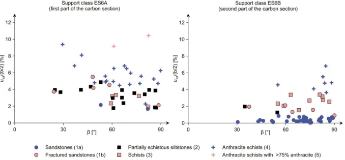
3 Carbon Section of the Lötschberg Base Tunnel ... 45
3.1 Introduction ... 45
3.2 Geology ... 45
3.3 Construction Method... 46
3.4 Rock response to tunnelling ... 48
3.5 Data Analysis ... 48
3.6 Conclusions ... 52
Notation ... 52
PART II: TUNNELLING PERPENDICULARLY TO ALTERNATING WEAK AND COMPETENT ROCK LAYERS ... 53
4 Introduction ... 55
5 Closed-form solution for the ground response curve in tunnelling perpendicularly to thinly alternating weak and competent rocks ... 57
5.1 Introduction ... 57
5.2 Perfectly plastic behaviour disregarding out-of-plane plastic flow ... 58
5.2.1 Problem statement ... 58
5.2.2 Incremental stress-strain relationships ... 59
5.2.3 Elastic part of the GRC ... 61
5.2.4 GRC part for elasto-plastic behaviour either of the weak or the hard layers ... 63
5.2.5 GRC part for elasto-plastic behaviour both of the weak and of the hard layers ... 67
5.2.6 Verification of the analytical solution ... 69
5.2.7 Dimensionless diagrams ... 72
5.3 Extension of the closed-form solution for brittle behaviour of the hard layers ... 73
5.3.1 Derivation ... 73
5.3.2 Verification of the analytical solution ... 75
5.4 Extension for out-of-plane plastic flow ... 76
5.4.1 Derivation ... 76
5.4.2 Verification of the analytical solution ... 80
5.5 Model behaviour ... 81
5.5.1 Perfectly plastic behaviour of the hard layers ... 81
5.5.2 Effect of brittle behaviour of the hard layers ... 85
5.6 Relevance of hard interlayers ... 85
5.7 Remarks concerning the adequacy of the homogenised model ... 86
5.8 Conclusions ... 87
Notation ... 88
6 Determination of equivalent parameters for a rock mass consisting of thinly alternating weak and competent rocks... 91
6.1 Introduction ... 91
6.2 Determination of the parameters of the equivalent isotropic medium ... 91
6.3 Relationships between the material constants of the equivalent isotropic medium and those of the transversely isotropic medium ... 93
6.4 Accuracy of the proposed simplified model ... 95
6.5 Application examples ... 97
6.6 Closing remarks ... 98
Notation ... 99
7 Influence of the heterogeneity scale on the squeezing variability along
the tunnel ... 101
7.1 Introduction ... 101
7.2 Longitudinal distribution of the displacements ... 101
7.3 A simple equation for the displacements in a weak zone considering a wall-effect ... 103
7.4 Conclusions ... 107
Notation ... 107
PART III: TUNNELLING PARALLEL TO ALTERNATING WEAK AND COMPETENT ROCK LAYERS ... 109
8 Introduction ... 111
9 Response of a thinly stratified rock mass, striking parallel to tunnel axis ... 113
9.1 Introduction ... 113
9.2 Constitutive model ... 113
9.2.1 Formulation of the constitutive model ... 113
9.2.2 Rock element behaviour ... 114
9.3 Basic aspects of the bedded rock response to excavation ... 117
9.4 Development of nomograms ... 123
9.5 Parameters of an equivalent isotropic material ... 125
9.5.1 Procedure ... 125
9.5.2 Application examples ... 128
9.6 Conclusions ... 128
Notation ... 129
10 Influence of the heterogeneity scale on the distribution of the ground displacements in the profile ... 133
10.1 Introduction ... 133
10.2 Adequacy of the homogenised model ... 133
10.3 Tunnelling parallel to the interface between a weak and a competent formation ... 140
10.4 Alternating weak and competent layers of medium thickness ... 142
10.5 Conclusions ... 142
Notation ... 142
11 Response of a schistous rock mass striking parallel to the tunnel axis ... 145
11.1 Introduction ... 145
11.2 Constitutive model ... 147
11.2.1 Formulation of the constitutive model ... 147
11.2.2 Rock element behaviour ... 149
11.3 Basic aspects of the schistous rock response to excavation ... 150
11.4 Development of nomograms ... 155
11.5 Parameters of an equivalent isotropic material ... 157
11.6 Conclusions ... 158
Notation ... 159
PART IV: TUNNELLING WITH AN ARBITRARY ANGLE TO THE SCHISTOSITY OR BEDDING PLANES ... 161
12 Influence of the orientation of the anisotropy planes on the squeezing deformations ... 163
12.1 Introduction ... 163
12.2 Tunnelling in schistous rock, perpendicular to the strike direction ... 165
12.2.1 Influence of the dip angle on the displacements ... 165
12.2.2 Influence of the dip angle on the pre-deformations ... 169
12.2.3 Influence of the dip angle on the convergences ... 170
12.3 Tunnelling in thinly stratified rock, perpendicular to the strike direction ... 172
12.3.1 Influence of the dip angle on the displacements ... 172
12.3.2 Influence of the dip angle on the pre-deformations ... 172
12.3.3 Influence of the dip angle on the convergences ... 175
12.4 Arbitrary strike ... 175
12.5 Conclusions ... 177
Notation ... 178
13 Variability of squeezing deformations in folded rocks ... 181
13.1 Introduction ... 181
13.2 Problem definition ... 182
13.3 Schistous rocks ... 185
13.4 Stratified rocks ... 191
13.5 Case history of the Sedrun section of the Gotthard Base Tunnel ... 194
13.6 Conclusions ... 196
Notation ... 196
PART V: DEALING WITH THE SQUEEZING VARIABILITY IN SHIELDED TBM TUNNELLING ... 199
14 Higher capacity segmental lining systems ... 201
14.1 Introduction ... 201
14.2 Lining systems ... 201
14.3 Single shell segmental lining made of normal-strength concrete ... 204
14.4 Single shell segmental lining made of (U)HPC ... 206
14.4.1 Principle and manufacture ... 206
14.4.2 Mechanical properties ... 206
14.4.3 Design ... 207
14.4.4 Durability ... 207
14.4.5 Fire behaviour ... 208
14.4.6 The use of (U)HPC for segmental linings ... 209
14.5 Double shell lining consisting of two segmental rings ... 210
14.6 Double shell lining with inner ring of cast in-situ concrete ... 211
14.7 Load bearing capacity of the lining systems ... 212
14.7.1 Single or double shell systems of uniform quality concrete ... 212
14.7.2 Double shells of different quality concretes ... 213
14.8 Rock pressure ... 214
14.9 Comparative cost analysis ... 218
14.10 Conclusions ... 225
Notation ... 225
15 Deformable segmental lining systems ... 227
15.1 Introduction ... 227
15.2 Basic considerations ... 229
15.2.1 Deformation capacity ... 229
15.2.2 Load-displacement and stress-strain behaviour ... 230
15.2.3 Installation procedure ... 232
15.2.4 Serviceability ... 232
15.2.5 Bearing capacity ... 232
15.2.6 Monitoring ... 233
15.2.7 Costs ... 233
15.3 Structural assessment ... 233
15.3.1 Computational model ... 233
15.3.2 Computational example ... 234
15.3.3 Design diagrams ... 235
15.4 Structural comparison: resistance vs. yielding principle ... 238
15.5 Cost comparison: resistance vs. yielding principle ... 242
15.5.1 Tunnel costs for a specific geotechnical situation ... 242
15.5.2 Tunnel costs considering squeezing distribution ... 244
15.6 Conclusions ... 247
Notation ... 247
Conclusion and perspectives ... 249
APPENDIX ... 257
Appendix A: Tunnelling perpendicularly to a thinly stratified rock mass – Coefficients of the incremental stress strain relationships ... 259
A.1 Case i. Both the weak and the hard layers behave elastically ... 259
A.2 Case ii. Weak layers yield in-plane, hard layers behave elastically ... 260
A.3 Case iii. Hard layers yield in-plane, weak layers behave elastically ... 261
A.4 Case iv. Both the hard and the weak layers yield in-plane ... 263
A.5 Case ii-o. Weak layers yield out-of-plane in triaxial extension, hard layers behave elastically... 265
A.6 Case iii-o. Hard layers yield out-of-plane in triaxial extension, weak layers behave elastically ... 266
A.7 Case iv-o1. Weak layers yield out-of-plane in triaxial extension, hard layers yield in-plane ... 268
A.8 Case iv-o2. Weak layers yield in-plane, hard layers yield out-of-plane in triaxial extension ... 270
A.9 Case iv-o3. Both the weak and the hard layers yield out-of-plane in triaxial extension ... 271
A.10 Case iv-o4. Weak and hard layers yield out-of-plane in triaxial compression and extension, respectively ... 272
A.11 Case iv-o5. Weak and hard layers yield out-of-plane in triaxial extension and compression, respectively ... 273
Appendix B: Tunnelling perpendicularly to a thinly stratified rock mass – Dimensionless diagrams for the displacements ... 275
Appendix C: Tunnelling perpendicularly to a thinly stratified rock mass – Flow chart of the Matlab-code for calculating the GRC ... 285
Appendix D: Stratified rock mass – Implementation and validation of the constitutive model ... 295
D.1 Elastic homogenisation ... 295
D.2 Elasto-plastic homogenisation ... 296
D.3 Schematic stress-point algorithm ... 297
D.4 Validation of the constitutive model analogously to Lourenço (1995) ... 297
D.5 Validation of the constitutive model considering the problem of tunnelling perpendicular to the layers of a thinly stratified rock mass ... 298
Appendix E: Tunnelling parallel to the bedding of a thinly stratified rock
mass – Dimensionless diagrams for the displacements ... 301
Appendix F: Schistous rock mass – Implementation and validation of the constitutive model ... 311
F.1 Model formulation ... 311
F.2 Schematic stress-point algorithm for the 2D case ... 313
F.3 Schematic stress-point algorithm for the 3D case ... 314
F.4 Validation examples ... 315
Appendix G: Tunnelling parallel to the schistosity plane – Dimensionless diagrams for the displacements ... 317
Notation ... 323
References ... 327
Introduction
Problem statement
“Squeezing ground” is characterised by large time-dependent deformations that develop when tunnelling through weak rocks. The magnitude of squeezing deformations in tunnelling often varies over short distances even where there is no obvious change in the construction method, in the depth of cover, in the lithology or rock structure. As long as the reasons for the variability are not known, the tunnelling-induced convergences cannot be predicted with sufficient reliability. Reliable predictions, however, are important for determining the temporary support or the excavation diameter. Otherwise, large-scale tunnel repairs may be necessary, which can cause delay and additional costs due to remedial actions as well as due to the enforced interruption of other operations in progress at the same time. The variability of squeezing intensity is one main cause of setbacks that even highly qualified engineers may experience in some cases (Kovári 1998).
For a given overburden and construction method, it is known that the rock deformations depend on the mechanical properties of the rock, on the spatial orientation of the stratification or schistosity, on the initial stress state and on the pore water pressure. It is, therefore, obvious that the reasons for the squeezing variability during the advance must be the variability of these influencing factors along the tunnel. In spite of the intensive research of the last years on the problem of squeezing ground, it is not known to what extent these factors influence the rock behaviour and how they can be taken into account during design, particularly if they change within short distances along the tunnel. This is for example the case when tunnelling through alternating weak and hard layers (Fig. 1a) or through folded rocks (Fig. 1b).
Figure 1. Tunnel drive through, (a), alternating weak and hard layers, (b), through folded rocks.
The goals of the present doctoral thesis are thus to improve safety and economic efficiency of tunnel constructions in squeezing ground, to improve the understanding of the squeezing variability and to make the related experiences from the AlpTransit project available to the
engineering community. The main objectives serving these goals are: (i) the identification of the factors, which are responsible for the squeezing variability, and (ii) the quantification of the influence of these factors, in order to use them as indicators during construction for the timely identification and prediction of the squeezing behaviour. To achieve these objectives, the data from the Gotthard, Ceneri and Lötschberg Base Tunnels are analysed qualitatively- empirically, numerical calculations are performed to investigate quantitatively the influence of the factors and decision aids for the planning, design and construction of tunnels are developed. Particular attention is paid to factors that influence convergences sensitively, i.e., whose variations – even if relatively small – may cause a significant variability in the macroscopic behaviour. Therefore, this thesis focuses on the squeezing variability due to the heterogeneity of the ground with respect to its mechanical characteristics at different scales as well as the variation of the orientation of the anisotropy planes (bedding, schistosity). In this thesis, the time-dependence of the rock behaviour (due to creep or consolidation) will not be considered. Furthermore, it is known that the initial stress state may influence the squeezing intensity: If the initial stress state varies along the tunnel, as it may be the case in intensively folded rocks or in fault zones, the intensity of squeezing may be variable. The effect of in situ stress variations will not be studied in this thesis.
Structure of the thesis
The thesis is structured in five parts, where some of the parts have already been published in scientific papers.
Part I analyses the observations of the construction of the three AlpTransit Base Tunnels.
Specifically, it gives a concise overview of the available data concerning the geology, the excavation and support and the rock response to tunnelling for different sections of the Gotthard (Chapter 1), Ceneri (Chapter 2) and Lötschberg Base Tunnels (Chapter 3) and identifies the factors that are responsible for the squeezing intensity and variability.
Furthermore, the influence of these factors is discussed and empirical correlations are established that allow to improve the predictions of the tunnelling-induced convergences.
The observations of the construction of the AlpTransit tunnels could show that the squeezing variability can be traced back to variations of the structure of the ground, such as the variation of the mechanical properties of the rock (for example when tunnelling through alternating weak and competent rocks) or the variation of the orientation of the schistosity to the tunnel axis due to folding.
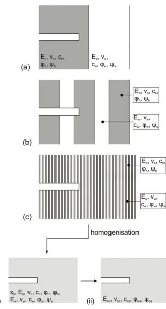
The theoretical background of these observations is provided in Parts II to IV of this thesis, which investigate the squeezing intensity in tunnelling through alternating weak and competent rocks (Fig. 1a) or through folded rocks (Fig. 1b) by means of analytical methods or numerical computations. For the analysis of tunnelling through alternating weak and competent layers, three cases are distinguished with respect to the orientation of the layers (cf. Fig. 2): a sequence of alternating weak and hard rocks lying (a) perpendicular, (b) parallel or (c) with an arbitrary orientation to the tunnel axis. In the first case, the squeezing intensity may be very variable depending on the thickness of the layers with respect to the tunnel radius, i.e., on the scale of the mechanical heterogeneity of the ground.
In the second case (cf. Fig. 2b), the squeezing intensity is constant along the tunnel axis, but the deformations are not uniform along the tunnel profile. As was observed during the construction of the Gotthard and the Ceneri Base Tunnels, these two geotechnical situations can effectively occur in reality and are thus of particular practical importance. Of course, in reality, such a sequence of hard and weak layers may be characterised by transition zones.
Nevertheless, for simplicity reasons, this thesis focuses on an advance through a sequence of only one hard and one weak material.
Figure 2. Investigated orientations of the layers to the tunnel axis for a sequence of alternating weak and hard rocks.
Parts II and III focus on the displacements of the ground in cross-sections far behind the tunnel face. These are greater than the convergences of the excavated profile because they include the deformations that occur ahead of the face (so-called “pre-deformations”). As shown in Parts II and III, the pre-deformations (and thus also the convergences of the excavated profile) can be obtained with the known methods for isotropic elasto-plastic materials.
Part II investigates the excavation-induced displacements in tunnelling perpendicular to the layers (cf. Fig. 2a). If the alternating zones are thick relative to the tunnel diameter (Fig. 3a), the response of such formations to the tunnel excavation may exhibit a great variability, as was observed for instance in the Sedrun Section of the Gotthard Base Tunnel. If, however, the formation consists of very thin alternating weak and competent rock layers, the deformation distribution along the tunnel axis will be practically uniform (Fig. 3c). This means that rather than considering a heterogeneous model and modelling the individual layers numerically, which would be demanding in terms of spatial discretisation and computation time, the rock structure can be taken into account by considering a homogeneous, but nevertheless transversely isotropic model (Fig. 3i). For this special case, Chapter 5 develops a closed-form solution for the ground response curve (GRC; i.e., the relationship between the radial displacement at the tunnel boundary and the support pressure; Panet and Guellec 1974), using the homogenisation technique (see, e.g., Salamon 1968) and assuming rotational symmetry, plane strain conditions, perfectly plastic behaviour for the weak layers and either perfectly plastic or brittle behaviour (with post-failure decrease in strength) for the hard layers.
The response of the considered homogenised material to tunnelling is isotropic (since the excavation boundary experiences a uniform radial displacement). This suggests that it may be possible to consider the rock mass as an isotropic and homogeneous material (Fig. 3ii) with mechanical parameters, which depend on the parameters and fractions of the weak and hard layers. Such an approach would be useful in practice because it would allow using common calculation methods and programs to solve problems that do not meet the conditions of rotational symmetry or plane strain and this even for thinly stratified rocks.
Chapter 6 investigates this idea into more depth and determines the equivalent parameters (Young’s modulus Eeq, Poisson’s ratio νeq, friction angle φeq, cohesion ceq and dilatancy angle ψeq, Fig. 3ii) of an isotropic homogeneous rock mass as a function of the properties and fractions of the weak and the hard layers.
Figure 3. Problem statement for alternating weak and hard layers lying perpendicular to the tunnel axis.
The results of Chapters 5 and 6 apply to alternating weak and hard layers that are so thin (relative to the tunnel radius) that the rock mass can be considered as homogeneous at the scale of the tunnel cross-section. Otherwise, if the layers are thicker and thus the assumption of a homogenised model is not valid, at the current state of research numerical calculations have to be performed, where the weak and the hard layers have to be modelled discretely.
However, Chapter 7 shows that the displacements in weak zones can be estimated by means of a simple equation which takes into account the stabilising influence of the adjacent hard layers.
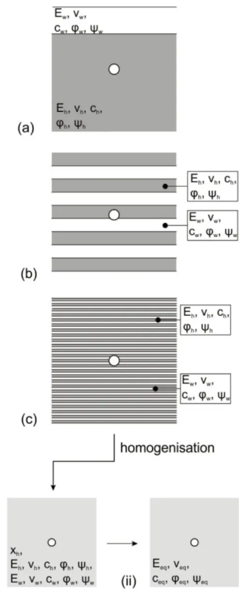
Part III investigates the excavation-induced tunnel displacements in stratified rock mass, consisting of alternating weak and hard layers that are oriented parallel to the tunnel axis (Fig. 2b). Obviously, if the layers are very thick and their interface lies at a great distance to the tunnel (Fig. 4a), then the displacements of the tunnel profile will be practically uniform and thus the heterogeneity of the ground can be neglected. Otherwise (Fig. 4b), the squeezing deformations along the tunnel profile will not be uniform, even if the layers are very thin (Fig. 4c).
Figure 4. Problem statement for alternating weak and hard layers lying parallel to the tunnel axis.
Tunnelling through thinly alternating weak and hard layers that strike parallel to the tunnel axis can be analysed by considering, analogously to Chapter 5, a homogeneous and transversely isotropic medium (Fig. 4i; Chapter 9). However, in contrast to Chapter 5, the conditions of rotational symmetry are not fulfilled anymore and, consequently, this boundary value problem has to be solved numerically. Therefore, the constitutive model of Chapter 5 was formulated for general 3D stress- and strain-states (using the homogenisation technique of Lourenço 1995) and implemented in Abaqus. The material constants of this equivalent homogeneous model consist of the thickness fractions and mechanical parameters of the alternating layers. Using this model, a comprehensive parametric study was carried out covering a wide range of geotechnical parameters. The results are presented in the form of dimensionless design diagrams that allow for a quick estimation of the maximum and minimum displacements of the tunnel profile. Even if the response of the ground is anisotropic in this case, these diagrams can also be used, analogously to Chapter 6, to determine the parameters for an isotropic homogeneous rock mass (Fig. 4ii), which is equivalent to the isotropic rock mass in the sense that its tunnelling-induced displacements are equal either to the maximum or to the minimum displacements of the anisotropic model.
As shown in Section 9.5, using this equivalent isotropic model makes it possible to find an
upper and a lower bound of the displacements in more complex problems (that do not meet the condition of plane strain).
Finally, Chapter 10 examines the adequacy and limits of the homogenisation of a stratified rock mass and the influence of the layer thickness.
Chapter 11 concerns the case of tunnelling through schistous rocks striking parallel to the tunnel axis. The reason for considering schistosity in Part III (which actually deals with stratified rock masses) is that the response of a schistous rock mass exhibits certain similarities to that of a stratified rock mass: A schistous rock mass can be conceived, from the mechanical point of view, as a borderline case of a thinly stratified rock mass. Schistosity is irrelevant for tunnelling perpendicular to the layers (Fig. 3c), but has a pronounced influence on the displacements if the schistosity plane strikes parallel to the tunnel axis.
Since the constitutive model that was implemented for thinly stratified rocks in Chapter 9 is computationally inefficient for the borderline case of schistosity, Chapter 11 starts with the formulation of an optimised constitutive model specifically for schistous rock, continues with the investigation into the effect of schistosity on the displacements and closes with working out design diagrams that allow a quick estimation of the tunnel displacements in schistous rocks (assuming again plane strain conditions) for a wide parameter range.
Part IV considers tunnelling through thinly stratified or schistous rock masses with an arbitrary orientation of the anisotropy planes with respect to the tunnel axis (cf. Fig. 2c). First, in Chapter 12, the relatively simple case of constant orientation of the anisotropy planes along the tunnel is considered, while paying attention to the effect of the dip angle and strike of the anisotropy planes relative to the tunnel axis on the pre-deformations and thus on the deformations of the excavated tunnel profile (“convergences”). The pre-deformations depend essentially on the orientation of the anisotropy planes and, as shown in Section 12.2.2, may be considerably higher than those estimated with the known methods which were developed for isotropic materials. Chapter 12 shows a simplified method for estimating the tunnel convergences.
Subsequently, Chapter 13 analyses numerically the case of tunnelling through folded rock formations (Fig. 1b), where the orientation of the anisotropy planes and consequently the squeezing intensity vary along the tunnel axis. A simplified folded rock structure is considered with a sinusoidal form of the bedding or schistosity surface. Folding is taken into account numerically in the constitutive models by considering that the normal vector to the anisotropy surface is position-dependent. The numerical results show that the variability of the convergences depends essentially on the amplitude and period of the anisotropy surface.
Finally, Chapter 13 revisits the case history of the Sedrun section of the Gotthard Base Tunnel, providing the theoretical background of the schistosity factor introduced in Chapter 1.
The last part of the thesis investigates the aspect of squeezing variability from a completely different perspective: Part V studies technological possibilities for dealing with squeezing variability in the very important case of mechanised tunnelling with shielded TBMs, since they are particularly vulnerable to squeezing: TBM offer only a very limited space for deformations to occur and, consequently, even relatively small convergences may lead to considerable difficulties such as shield jamming or damage to the segmental lining.
Depending on the design, the decision-making during construction may have to address the boring diameter (to provide more space for deformations), the lining type or even the lining thickness, whereby the timely implementation of such measures is a demanding task if
squeezing intensity changes frequently along the tunnel drive. The thesis focuses on the problem of overstressing of the segmental lining (the most serious hazard of shield tunnelling in squeezing rock), and investigates, whether higher bearing or deformation capacity lining systems (Chapters 14 and 15), respectively, could widen the application range of shielded TBMs. Furthermore, the chapters discuss the possibility of installing linings of variable thickness or type (e.g., switching from normal to higher strength segments or from a stiff to a deformable lining of the same thickness). The structural assessment of the various lining types is based on numerical analyses which consider the interaction between the advancing shield, the ground and the lining, whereby the rock mass is taken as homogeneous and isotropic. This assessment can also be adopted for stratified or schistous rocks considering equivalent parameters based on the guidelines formulated in the Chapters 6, 9 and 11.
Concerning the possibilities for increasing the bearing capacity of stiff lining systems (Chapter 14), besides the obvious option of increasing segment thickness, an investigation is made into the technical and economical feasibility of double shell solutions as well as that of high performance or ultra-high performance concretes from the standpoints of structural engineering, TBM technology, process engineering, material technology and construction cost.
Deformable lining systems (Chapter 15) exploit a basic feature of squeezing ground: the rock pressure decreases when deformations are allowed to occur. Two basic options are investigated: radially deformable linings, where rock deformations occur outside the lining extrados; and tangentially deformable linings which can accommodate a reduction in their circumference. Finally, the deformable linings are compared to the stiff linings and the geological conditions are investigated for which the use of deformable lining systems is structurally adequate and economical.
Remarks
In this thesis, as usual in geotechnics, compression will be taken as positive for the stresses and the strains.
Each chapter of this thesis is presented as an autonomous entity with its notation inserted at its end, while all references are given together at the end of the thesis.
Publications
Chapter 1 was published in Mezger et al. (2013a) and presented in Mezger et al. (2013b), whereby the contribution of Dr. Hans-Jakob Ziegler concerned geological aspects. Chapter 2 was presented in Mezger and Anagnostou (2015). Chapters 14 and 15 were published in Mezger et al. (2017) and Mezger et al. (2018), respectively, under consideration of the comments and suggestions of Dr. Marco Ramoni, who helped to improve the papers (on the basis of his own doctoral thesis). These chapters have also been presented on several occasions (Mezger et al. 2015b, Mezger et al. 2015a, Mezger et al. 2016).
PART I: ANALYSIS OF CASE HISTORIES
This part of the thesis analyses the observations of the construction of the three AlpTransit Base Tunnels. Specifically, it gives a concise overview of the available data concerning the geology, the excavation and support and the rock response to tunnelling of various sections of the Gotthard, Ceneri and Lötschberg Base Tunnel and identifies the factors that are responsible for the squeezing intensity and variability. Furthermore, the influence of the factors are analysed qualitatively – empirically, in order to establish correlations that can be used for making more reliable predictions of the tunnelling-induced convergences. It is shown that the squeezing deformations in a specific tunnel cross-section are mainly affected by the lithology, the orientation of the schistosity planes and the existence of nearby weaker or stronger zones.
1 Sedrun Section of the Gotthard Base Tunnel
11.1 Introduction
The magnitude of squeezing deformations occurring in tunnelling often varies over short distances even where there is no obvious change in the excavation method, depth of the cover and lithology. The variability of the ground response to excavation is one of the causes of the setbacks observed sometimes in tunnelling through squeezing rock (Kovári 1998). As long as the reasons for the variability are not identified and understood, the tunnelling- induced convergences cannot be predicted with sufficient reliability. Reliable predictions, however, are important for determining the temporary support or the excavation diameter.
Otherwise, large-scale tunnel repairs may be necessary, which can cause, as may be seen for example in the southern section of the Gotthard Base Tunnel (Bachmann and Vicenzi 2008), delay and extra costs due to remedial actions as well as due to the enforced interruption of other operations in progress at the same time. For reviews on the problem and the mechanics of squeezing in tunnelling see Kovári (1998) and Barla (2002).
Figure 1.1. Longitudinal geological profile of the Gotthard Base Tunnel (from SKH Geologen AG 2011).
The 57 km long Gotthard Base Tunnel is the core of the AlpTransit project (Kovári et al.
1999). The project offers the possibility of moving the majority of the goods traffic crossing the Alps from road to rail and guarantees the connection of Switzerland to the European high-speed railway network for passenger traffic. The tunnel crosses the Aare massif, the Tavetsch-Massif, the Gotthard massif and the penninic gneiss zone (Fig. 1.1) from north to south. These tectonic units consist predominantly of granites, gneisses and schists (Kovári et al. 1999). The present chapter focuses on the Clavaniev Zone (abbreviated to CZ, Fig. 1.2) and on the Intermediate Tavetsch-Massif (abbreviated to TZM, Fig. 1.2), where heavily squeezing conditions were expected in the planning phase and also encountered during construction.
1 This chapter has been published in: Mezger, F., Anagnostou, G., Ziegler, H. J. (2013). The excavation- induced convergences in the Sedrun section of the Gotthard Base Tunnel. Tunnelling and Underground Space Technology, Vol. 38: 447‒463.
Figure 1.2. Detail of the geological profile of the Gotthard Base Tunnel (from Guntli and Weber 2009).
The aim of this chapter is to identify factors that have a significant influence on the convergences and might be used as indicators during construction for the timely identification of squeezing conditions. The chapter starts with a concise overview of the available data concerning the geology, the excavation and support and the rock response to tunnelling (Sections 1.2 to 1.4) and then seeks for empirical correlations between the deformations observed during construction and the lithological and structural features of the rock mass (Section 1.5). The analysed tunnel section crosses the northern TZM and the Clavaniev Zone, hereafter referred to as “Sedrun North” (Fig. 1.2), and includes both the north-western and north-eastern tubes. The two tubes are separated by a centreline distance of 50 to 70 m.
Section 1.5 demonstrates that the observed convergence correlates reasonably well with the degree of shearing and the schistosity orientation of the rock. In addition, Section 1.5 discusses the effect of nearby zones of more or less competent rock (Kovári and Anagnostou 1995, Cantieni and Anagnostou 2007) as well as the usefulness of the displacement vector orientation for predictions (Steindorfer 1998). Finally, Section 1.6 checks the predictive capability of the empirical correlations obtained in Section 1.5 by calibrating them, based on the observations in a part of the tunnel, applying them to the remaining stretch of tunnel and comparing the empirical predictions with the measured deformations. Section 1.6 shows that the comparison is satisfactory and concludes that the empirical relationships in combination with advance probing are in fact very useful for estimating the squeezing intensity ahead of the tunnel face.
The present chapter evolved within the framework of a long-term research programme at the ETH Zurich on squeezing ground. It is closely related in particular to the work of Cantieni et al. (2011), which examined the possibility of predicting ground response to tunnelling on the basis of the axial extrusion of the core ahead of the face. Cantieni et al. (2011) also analysed the monitoring data from the construction of the western tube of the Gotthard Base Tunnel.
However, they could not find a clear correlation that would allow them to predict con- vergences with sufficient reliability on the basis of extrusion monitoring alone and proposed evaluating extrusion data in combination with other information, such as advance probing.
1.2 Geology
The Gotthard Base Tunnel crosses the Clavaniev Zone and the northern TZM over a length of 285 m and 793 m, respectively. The depth of cover is about 800 m. The tectonic units consist of different rock types: Gneisses alternate with steeply inclined layers composed of soft phyllites and schists, which have a thickness in the range of decimetres to decametres (Kovári et al. 1999). The major part of these units consists of so-called kakiritic rocks, i.e.
rocks that are systematically interspersed with shear planes filled with rock fragments (fault breccia) or more finely ground material (fault gouge). In general, the term “kakirite” denotes
“a broken or intensively sheared rock, which has lost a large part of its original strength”
(Schneider 1997). Vogelhuber (2007) and Anagnostou et al. (2008) performed a total of 112 consolidated drained and undrained triaxial tests to obtain the strength parameters of the kakiritic rocks in the Sedrun section. Depending on the development of the failure surface, a distinction is made between anisotropic and isotropic failure to evaluate the strength parameters. Anisotropic failure occurs when the failure surface develops through the existing discontinuity, e.g. through a plane of schistosity. Figure 1.3 shows the strength parameters determined from triaxial tests. The friction angles are between 25 and 30° and the cohesion- values between 200 and 600 kPa. Figure 1.3 considers only samples with isotropic failure. In the case of anisotropic failure, the friction angle was about 25º and the cohesion-values were mostly below 200 kPa.
Figure 1.3. Cohesion c and angle of internal friction φ of samples with isotropic failure (after Ana- gnostou et al. 2008).
The Clavaniev Zone is located at the southern boundary of the Aare massif and was intensively sheared and strongly deformed tectonically during the alpine orogeny (Schneider 1997). The degree of kakiritization is variable. About 67% of the rocks in the northern TZM and over 95% of the rocks in the Clavaniev Zone may be designated as kakirites. The rest of the gneisses and slates are at least interspersed with irregular hairline cracks. The weak, kakiritic rocks in the encountered section of the tunnel are saturated but have a very low permeability (k = 10-8 m/s to 10-10 m/s according to Vogelhuber 2007).
The following section provides an overview of the available information on the encountered geology based on the data in the integrated web platform of the Gotthard Base Tunnel project (SISO 2012) and the synthesis report by Guntli and Weber (2009). Some lithologic
and structural characteristics of the rock (lithological type, degree of shearing and schistosity), which were deemed to be important for its response to tunnelling, have been codified using project-specific classifications, which are presented in Figures 1.4 to 1.8 and are discussed below.
Table 1.1. Rock mass classification on the basis of the degree of shearing F (after Guntli and Weber 2009).
Degree of shearing
F Description
1 Competent
2 Sporadic shear fractures, slickensides
3 Schistous and laminated rocks, mylonites, phyllites
4 Sheared, fractured rocks (portion of rock flour <10%, disturbed over < 25% of the tunnel face surface)
5 Sheared, crumbly, friable rocks (portion of rock flour 10‒30%, disturbed over > 25% of the tunnel face surface)
6 Rocks with a portion of rock flour > 30% and plastic consistency. It can be deformed by hand and disturbed over the majority of the tunnel face surface.
During advance, the ground was classified into rock types based upon both the lithology and the degree of shearing F, which was introduced as a project-specific measure of the tectonic disturbance of the rock mass. Six classes for the degree of shearing were defined (Table 1.1) according to the fraction of rock powder, resulting from the failure of the rocks during their tectonic overstressing in the geologic past. The lithological types T are presented in Table 1.2. The quality of the intact rock (on the scale of a specimen) decreases from lithological type 1 (which includes the strongest units, such as amphibolites or quartzites) to lithological type 9 (completely kakiritized, fine grained material). The last two types in Table 1.2 do not represent lithological types in the narrow sense, but have been included because heavily sheared rocks on account of their nature (almost engineering soil) can be seen as another lithological type.
Table 1.2. Rock mass classification on the basis of the lithology (after Guntli and Weber 2009).
Lithological type
T Description
1 Pegmatites, amphibolites, quartzites
2 Quartz- and feldspar-rich gneisses, migmatites 3 Striped gneisses
4 Gneisses with a high content of mica, dolomites 5 Gneisses with a high content of schists
6 Schists 7 Phyllites 8 Kakirites (fault gouge)
9 Kakirites with high plasticity and high percentage of fines
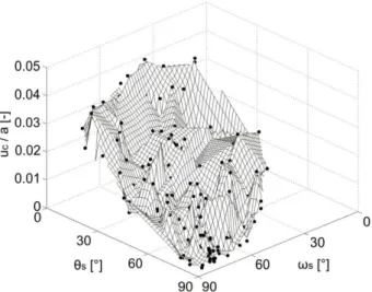
Figure 1.4. Data for chainage 1100 to 1300 m. Average magnitude of the projections of the displacement vectors in the cross-sectional plane of the tunnel normalised by the tunnel radius (uc/a) along the tunnel as well as, (a), degree of shearing F, (b), lithological type T and, (c), schistosity influence factor S (evaluation based upon the data from SISO 2012 and Guntli and Weber 2009).
Figure 1.5. Data for chainage 1300 to 1500 m. Average magnitude of the projections of the displacement vectors in the cross-sectional plane of the tunnel normalised by the tunnel radius (uc/a) along the tunnel as well as, (a), degree of shearing F, (b), lithological type T and, (c), schistosity influence factor S (evaluation based upon the data from SISO 2012 and Guntli and Weber 2009).
Figure 1.6. Data for chainage 1500 to 1700 m. Average magnitude of the projections of the displacement vectors in the cross-sectional plane of the tunnel normalised by the tunnel radius (uc/a) along the tunnel as well as, (a), degree of shearing F, (b), lithological type T and, (c), schistosity influence factor S (evaluation based upon the data from SISO 2012 and Guntli and Weber 2009).
Figure 1.7. Data for chainage 1700 to 1900 m. Average magnitude of the projections of the displacement vectors in the cross-sectional plane of the tunnel normalised by the tunnel radius (uc/a) along the tunnel as well as, (a), degree of shearing F, (b), lithological type T and, (c), schistosity influence factor S (evaluation based upon the data from SISO 2012 and Guntli and Weber 2009).
Figure 1.8. Data for chainage 1900 to 2100 m. Average magnitude of the projections of the displacement vectors in the cross-sectional plane of the tunnel normalised by the tunnel radius (uc/a) along the tunnel as well as, (a), degree of shearing F, (b), lithological type T and, (c), schistosity influence factor S (evaluation based upon the data from SISO 2012 and Guntli and Weber 2009).
The discontinuities of the rock were recorded during tunnel advance both with respect to the surfaces of schistosity and to the jointing. During advance it became evident that the degree of shearing F and the lithological type T are somehow connected with one other: in general, the higher the rock quality on the specimen scale, the smaller the degree of shearing.
Figure 1.9. Photograph of the tunnel face at a location with about 3% convergence and degree of shearing 4 (chainage 1300 m of the NE tube, from SISO 2012).
The alpine schistosity is clearly recognizable over major portions of Sedrun North and this even in strongly kakiritic reaches (Guntli and Weber 2009). In general, the strata dip steeply towards the north but are strongly disturbed by more recent shearing deformations. In fault zones, the intensive shearing (kakiritization) governs the behaviour of the rock mass.
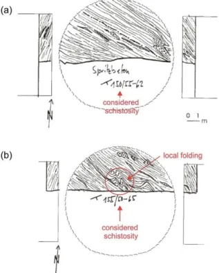
Figure 1.10. Geological mappings of the tunnel face with traces of the schistosity planes. (a) NW tube, chainage 1535 m; (b) NE tube, chainage 1202 m (after Guntli and Weber 2009).
However, since this shearing did not lead to a complete homogenisation of the rock mass, the older rock structure between these shear zones has been preserved (Guntli and Weber
2009). Thus, schistosity is still an important structural feature of the rock in the present case (Figs. 1.9 and 1.10). The so-called “schistosity influence factor” presented in Figures 1.4c to 1.8c is introduced in Section 1.5.2. It accounts for the orientation of the schistosity planes and combines their dip angle and dip direction in a single number.
Depending on the thickness of the beds, which were developed as a result of the schistosity, the rock mass was classified into classes from “schistous to phyllitic” (thickness < 0.5 cm) to
“not bedded” (thickness > 100 cm). Over 40% to 50% of the tunnel in the northern TZM and the Clavaniev Zone was assigned to the class “schistous to phyllitic” (Guntli and Weber 2009).
Figure 1.11. Longitudinal section and cross section of the yielding support system (after Ehrbar and Pfenninger 1999) and sequence of applying the support: 1: Excavation, 2: Sealing of the working area, 3: Installation of the steel ribs, 4: Installation of the radial bolts, 5: Application of the shotcrete ring.
As a consequence of the kakiritization of the rock and of the schistosity, the development of jointing was small. Only in the weakly kakiritized rock were small joints or hairline cracks present. The jointing in the TZM and the Clavaniev Zone was described as small for more than 72% of the tunnel length (Guntli and Weber 2009).
1.3 Construction Method
Due to the known presence and poor mechanical characteristics of kakiritic rocks, heavily squeezing conditions were expected for Sedrun North. Therefore, a circular tunnel cross- section in combination with full-face excavation and yielding support was chosen (Figs. 1.11 and 1.12a). The basic idea behind this concept has been explained by Kovári (1998): Full- face excavation makes it possible to have a statically favourable profile right from the start.
The yielding support, which consists of sliding steel ribs connected by friction loops (Fig. 1.12b), reduces the rock pressure to a manageable level (Kovári et al. 2000). With this method, deformations could occur, while providing continuous support of the rock. An over- excavation of 0.1 to 0.7 m (in radius) was foreseen in order to accommodate the convergences without impairing the necessary clearance profile. The steel ribs used were TH 44/70. In heavily squeezing rock, the steel ribs were spaced at 0.33–0.66 m, which leads to a steel quantity of up to 9.4 tons per linear metre (Kovári et al. 1999). Additionally, fully grouted bolts with a length of 8 to 12 m were installed (Fig. 1.11).
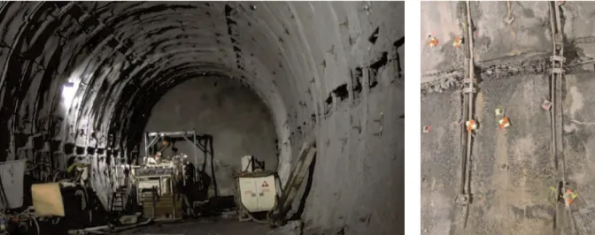
(a) (b)
Figure 1.12. (a) Tunnelling works at chainage 2155.5 m (from SISO 2012); (b) Support detail with steel ribs and friction loops (from SISO 2012).
After the rate of convergence slowed down a 0.3 to 0.6 m thick shotcrete ring was applied.
This was usually at a distance of about 30 m behind the tunnel face (approximately 1 month after excavation). In less squeezing ground, a stiff support was installed right from the start according to the so-called resistance principle (Kovári 1998).
Figure 1.13. Distribution of the applied support classes along the tunnel (after Guntli and Weber 2009).
To ensure stability of the tunnel face the ground ahead of the tunnel face was reinforced using 40 to 60 12 m-long steel bolts and steel fibre-reinforced shotcrete was applied to the face immediately after each excavation step. Additionally, systematic forepoling was used to prevent rock loosening and rock fall.
Table 1.3 and Figure 1.13 show the definition of the applied support classes, their distribution along the tunnel as well as the sequence of applying the support. The determination of the temporary support and of the excavation diameter during construction was based on the
results of design calculations, the experience gained with the rock and support behaviour from the already excavated tunnel section and the findings from advance core borings. More specifically, 28 horizontal advance core borings of lengths between 31 m to 196 m were carried out during tunnel construction in order to explore the prevailing rock conditions ahead of the tunnel face and to obtain rock samples for triaxial testing (Anagnostou et al. 2008).
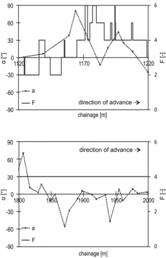
Figure 1.14 shows, for example, the estimated degree of kakiritization based on the obtained core (bottom of Fig. 1.14) as well as the encountered degree of shearing F after excavation (top of Fig. 1.14). Figure 1.14 shows that the shearing degree can be estimated on the basis of advance core drilling but is still subject to some uncertainty.
Figure 1.14. Comparison of the borehole findings (degree of kakiritization) with the encountered geology (degree of shearing F) of the chainage 1650 m to 1750 m of the NW tube (evaluation based upon the data from SISO 2012 and Guntli and Weber 2009).
Table 1.3. Definition of the support classes applied in Sedrun North (after Guntli and Weber 2009).
Support class SA 2.3 SA 4.1 SA 4.1+ SA 4.2 SA 4.2+
Excavated radius [m] 4.70 5.14 5.69 5.69 6.24
Over-excavation [cm] 10 30 50 50 70
Length of round [m] 1-2 1-1.5 1-1.34 1.34 1
Type of steel ribs [-] TH 29/70 TH 44/70
Sliding resistance [kN] 4 friction loops x 100 kN = 400 kN per connection
Spacing of steel ribs [m] 1.0-2.0 1-1.5 0.67-1.34 0.67 0.33/0.67- 1.0
Radial bolts, type [-] Ø 25 mm, 320 kN, S500
Radial bolts, length [m] 6 6-8 8 8-12 8-12
Radial bolts, quantity [-] 13-14 17-28 17-28 11-25 28
Face bolts, length [m] 12 12 12-18 12 12-18
Face bolts, quantity [-] 40 40 50 50 60
Forepoling, length [m] 8 6 6-8 6 6
Forepoling, quantity [-] 0-25 25-30 0-51 If required If required Thickness of the shotcrete ring [cm] 20-25 25-30 25-30 25-30 25-60 Thickness of the concrete lining [cm] 30 30 30 60 60
1.4 Rock response to tunnelling
In order to observe the behaviour of the rock and check the effectiveness of the tunnel support, a monitoring system with 3D optical measurements, radial extensometers, reverse-
head-extensometers (RH-extensometers, Thut et al. 2006) and measuring anchors was implemented.
− The convergences of the tunnel boundary during tunnel advance were monitored optically at monitoring stations spaced every 5 m to 20 m. Each monitoring station had 5 or 7 measuring points (Fig. 1.15). The displacements were measured at 165 monitoring stations in the NE tube and in 163 monitoring stations in the NW tube.
− 5 monitoring stations were instrumented with up to 5 radial extensometers of length 4–25 m to determine the extent of the rock zone around the tunnel affected by the excavation and thus the underlying rock deformation mechanism of the observed convergences. In some cases the measuring head was destroyed due to the large rock deformations so that no measurements were possible.
− To determine the load on the radial anchors, 4 m long measuring anchors were installed in 2 monitoring stations.
− The RH-extensometers served to observe the extrusion of the tunnel face as well as the axial deformation of the core ahead of the face.
Figure 1.15. Monitoring station with 5 (numbers with apostrophes) or 7 measuring points (numbers without apostrophes).
The optical measurements were the most important means of observing the behaviour of the tunnel since they were installed frequently and systematically in contrast to the other measurements. For this reason, the present chapter analyses only the optical measurements (Sections 1.5 and 1.6). The results of the RH-extensometers have already been discussed by Cantieni et al. (2011).
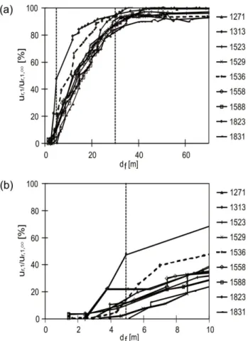
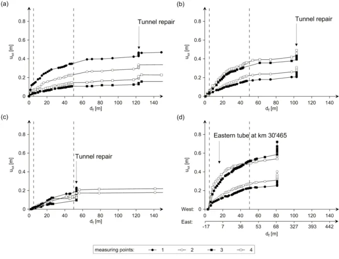
Figure 1.16a illustrates the typical development of the convergence. The diagram shows the vertical displacement ur,1 of the crown (normalised by its value ur,1,∞ far behind the face) as a function of the distance to the tunnel face df. Each curve of the diagram corresponds to a different monitoring station. It is readily seen that the biggest portion of the convergence took place within two tunnel diameters behind the face and that significant long-term deformations (which were initially feared) did not occur (Kovári and Ehrbar 2008). The figure also shows that the shotcrete ring (which was applied at a distance of about 30 m behind the face) almost stopped the displacements.
Water inflows occurred only in the gneiss and weakly kakiritized sections of the formations, where hairline cracks allowed some water circulation. In the core boreholes small water quantities between < 0.1 l/s (dripping water) and 0.3 l/s were measured (Guntli and Weber 2009).