Research Collection
Doctoral Thesis
Reliability-based code calibration for timber in fire
Author(s):
Fahrni, Reto Publication Date:
2021
Permanent Link:
https://doi.org/10.3929/ethz-b-000475057
Rights / License:
Creative Commons Attribution-ShareAlike 4.0 International
This page was generated automatically upon download from the ETH Zurich Research Collection. For more information please consult the Terms of use.
ETH Library
DISS. ETH NO. 27285
RELIABILITY-BASED CODE CALIBRATION FOR TIMBER IN FIRE
A thesis submitted to attain the degree of DOCTOR OF SCIENCES of ETH ZURICH
(Dr. sc. ETH Zurich)
presented by RETO FAHRNI MSc ETH Civil Eng
born on 28.03.1992 citizen of Eriz, BE
accepted on the recommendation of
Prof. Dr. Andrea Frangi (ETH Zurich, Examiner)
Univ.-Prof. Dr.-Ing. Jochen Zehfuß (TU Braunschweig, Co-examiner) Prof. Dr. Bruno Sudret (ETH Zurich, Co-examiner)
2021
i
Acknowledgments
This thesis is the result of slightly over four years of discussions, debates, analyses, coding, challenges, etc. During that time, many colleagues and friends supported me and/or positively questioned my ideas. Thank you all! I’m sorry that I’ll forget one or another in the following acknowledgments.
First of all, I would like to thank my supervisor Prof. Dr. Andrea Frangi for convincing me to do a PhD and for his generous support and patience at all times. He also applied successfully for the funding of this project, which was kindly provided by the Swiss national science foundation (SNF) through the COST Action FP1404. I was lucky to be part of the marvelous timber group.
Thanks to the fantastic team spirit, it was always a pleasure to go to work. The input of the group at timber meetings, during coffee breaks, or at any other time was always helpful.
I am thankful for several out of hand, time consuming whiteboard sessions with Benjamin Kreis and Stephan Schilling about all kinds of non-thesis related problems. They caused headaches, but were always fun and lead to instructive solutions.
The experimental research done by the group provided many occasions for interesting distractions. I was lucky to attend experiments of Lukas Blank, Thomas Ehrhart, Robert Jockwer, Miriam Kleinhenz, Peter Kobel, Katharina Müller, Marcel Muster, Jelena Ogrizovic and Flavio Wanninger (among others). I’ll miss the shop talking and the tense moments waiting for failure.
Especially during my first days and months in the group, I was lucky to have the support of Michael Klippel, Joachim Schmid and Pedro Palma. Thanks to their open door, I got instant and profound answers to any fire related topic, saving me hours of literature study.
Since the timber group would not be the same without all of its members, the colleagues not mentioned yet deserve the same credit: Tsuyoshi Aoyama, Dominik Bissig, Philippe Grönquist, Chamith Karannagodage, Robert Kroyer, Claude Leyder, Konstantinos "Robustos" Voulpiotis and Jonas Wyder. Special thanks go to the good soul of the group, Johanna Saladin-Michel.
Besides the timber group, I’m also grateful for my many supporters: The group of Prof.
Dr. Bruno Sudret, especially Paul-Remo Wagner, supported me when it came to reliability or uncertainty related problems and the UQLab framework. Gianluca De Sanctis supported me all along my PhD with his inputs on reliability and fire. The coffee breaks with the steel groups of Prof. Dr. Mario Fontana and Prof. Dr. Andreas Taras were great to broaden the horizon and get in contact with proof readers such as Robert Kroyer. The team at the Bauhalle, especially Martin Viertel, was a great support during my experimental research in the fire lab. At the "Swiss Federal Laboratories for Materials, Science and Technology" (EMPA) I was always welcome in the carpenter’s shop of Daniel Heer.
Learning from the work of Prof. Dr. Jochen Köhler and Michele Baravalle from NTNU was a good start into code calibration. Some initial differences between our calibration frameworks could be eliminated thanks to their open code policy and their openness to discuss essential
ii
details. I’m grateful to the librarians at ETH Zurich, who spent hours searching and dusting off piles of old literature for me.
I consider myself lucky to have had the support of modern computers: The hardest simulation work was done by Brutus and Euler, the High-Performance Computing clusters of ETH. In the end, my machine did a great job as well, after making trouble right at the beginning of the Corona induced home office period. With the pragmatic remote support of Roberto Pascolo, this situation was handled best possible.
I am grateful to my family and to my friends from study and sport, in particular Jasmine Moser, for their constant support, regular distraction, beautiful hours in the mountains, shop talking, never ending discussions, questions and everything else it needs to keep me alive.
Mein herzlichster Dank gilt meinen Eltern, welche mich in allen Belangen stets unterstützt haben. Ich möchte mich hiermit für die tausenden, oft komplizierten Fragen entschuldigen, die ich seit meinem ersten Wort gestellt habe. Ich bewundere die Geduld, die ihr aufgebracht habt, um meine Fragen immer bestmöglich zu beantworten.
In the end, it is the search for answers that has brought me to this point. Many thanks to everybody who had to/tried to/did answer my questions so far and I’m sorry for all the questions to come.
Home office, Zürich, October 2020 Reto Fahrni
iii
Abstract
For the design of structures, codes such as the Eurocode guarantee the required structural safety, both for the permanent and the fire design. In timber construction, the fire resistance is usually verified with the standard fire curve, since Eurocode provides simple and accurate design models for this exposure. The current Eurocode for timber in fire (EN 1995-1-2:2004) has evolved historically and uses the 20% fractile value for the strength in case of fire instead of the typical 5% fractile value. This has recently been questioned and is therefore thoroughly investigated in this thesis. In principle, there is no evidence that the reliability level of the current code is insufficient. Therefore, this thesis investigates the influence of the chosen fractile value on the homogeneity of the reliability levels of arbitrary structures when designed in accordance with the calibrated code. For this purpose, several reliability-based code calibrations for timber structures exposed to standard fire were conducted.
To assess the accuracy of the code format, the used reliability model must be as accurate as possible. For this purpose, an analytical resistance model was developed, which is based on the observed charring behavior of timber. This model was fitted to results of finite element simulations that were considered accurate. The simulations consisted of bending beams with varying geometry and fire exposure. Then, the analytical model was fitted based on the ultimate bending moment of those simulations. Considering the uncertain parameters of the analytical model as random variables, the model can be used for the reliability analysis.
In order to achieve a homogeneous reliability level with arbitrary structures it is useful to introduce partial factors for parameters with large scatter. For this reason, the code format for timber in case of fire has been extended by a partial factor on the charring rate. In total 770 different bending beams were considered in the code calibration, in all of which the fire design is decisive over the permanent design. In the calibration, the partial factors on the charring rate and the strength were optimized so that the resulting reliability index of the structures deviated as little as possible from the target reliability index. It could be shown that the partial factor of the charring rate should be chosen slightly above one. At the same time, the partial factor for the strength needs to be chosen below one so that the mean reliability level is not changed. A partial factor below one is equivalent to an increase of the fractile value, which proves that a reduction of the fractile to 5% would not be meaningful since it decreased the homogeneity of the reliability indices resulting from the calibrated code format.
With reliability calculations and code calibrations for subsets of the considered structures, it was shown that the resulting reliability is significantly dependent on the fire exposure. Therefore, it would be advisable to differentiate the fire exposure in the code format.
Furthermore, different optimization criteria were compared. Slight differences in the calibrated partial factors were found. However, the different results should not be understood as deficiencies of the criteria, but as optima for different optimization targets.
v
Zusammenfassung
Bei der Bemessung von Bauwerken garantieren Bemessungsnormen wie der Eurocode die nötige Tragsicherheit, sowohl im gewöhnlichen Lastfall, als auch bei der Brandbemessung. Dabei wird im Holzbau der Brandfall in den allermeisten Fällen mit der Normbrandkurve nachgewiesen, da hier- für einfache und akkurate Bemessungsmodelle im Eurocode zur Verfügung stehen. Der aktuelle Eurocode für Holz im Brandfall (EN 1995-1-2:2004) ist historisch gewachsen und verwendet für die Festigkeit im Brandfall den 20 % Fraktilwert, anstatt des üblichen 5 % Fraktilwertes. Dies wurde jüngst infrage gestellt und soll durch diese Arbeit daher näher betrachtet werden. Grundsätzlich gibt es keinen Anhaltspunkt, dass die heutige Norm zu einem ungenügenden Zuverlässigkeit- sniveau führte. Daher konzentriert sich diese Arbeit darauf, die Verwendung des Frakilwertes im Hinblick auf das Erreichen eines möglichst homogenen Zuverlässigkeitsniveaus über beliebige Tragstrukturen hinweg zu untersuchen. Dazu wurde erstmalig eine Normkalibrierung basierend auf Zuverlässigkeitsanalysen für Holz unter Normbrandbeanspruchung durchgeführt.
Damit die Güte des Nachweisformats beurteilt werden kann, muss das Zuverlässigkeitsmod- ell so akkurat wie möglich sein. Zu diesem Zweck wurde ein analytisches, dem beobachteten Abbrand nachempfundenes Widerstandsmodell entwickelt. Dieses wurde an die Ergebnisse von Finite-Elemente-Simulationen angepasst, welche als akkurat angenommen wurden. Die Simula- tionen umfassten Biegeträger von unterschiedlicher Geometrie und Brandexposition. Basierend auf den resultierenden Widerstandsmomenten konnte danach das analytische Modell angepasst werden. Sodann konnte dieses Modell mit den entsprechend verteilten Zufallsvariablen als Zuver- lässigkeitsmodell verwendet werden.
Um das Ziel eines homogenen Zuverlässigkeitsniveaus über beliebigen Tragstrukturen zu erre- ichen, ist es sinnvoll, Teilsicherheitsfaktoren für Parameter mit grosser Streuung einzuführen. Aus diesem Grund wurde das Nachweisformat für Holz im Brandfall um einen Teilsicherheitsbeiwert auf der Abbrandrate erweitert. In die Normkalibrierung wurden 770 verschiedene Biegeträger einbezogen, bei welchen der Brandfall massgebend ist. Mit der Kalibrierung wurden nun die Teilsicherheitsbeiwerte der Abbrandrate und der Festigkeit dahingehend optimiert, dass die resul- tierende Zuverlässigkeit dieser Tragstrukturen in der Summe minimal von der Zielzuverlässigkeit abweicht. Dadurch konnte gezeigt werden, dass der Teilsicherheitsbeiwert der Abbrandrate le- icht über eins gewählt werden sollte. Gleichzeitig müsste der Teilsicherheitsbeiwert der Festigkeit unter eins gewählt werden, damit das Sicherheitsniveau im Mittel gleich bliebe. Dies käme einer weiteren Erhöhung des Fraktilwertes gleich, weshalb sich die Verwendung des 20% Fraktilwertes anstelle des 5% Fraktilwertes für die Festigkeit von Holz im Brandfall als sinnvoll heraus stellte.
Anhand von separaten Analysen und Kalibrierungen für Untergruppen der Tragstrukturen konnte gezeigt werden, dass die Zuverlässigkeit deutlich von der Brandexposition abhängig ist.
Es würde sich daher anerbieten, die Brandexposition im Nachweisformat zu unterscheiden.
Weiter wurden unterschiedliche Optimierungskriterien verglichen. Dabei zeigten sich ger- ingfügige Unterschiede in den kalibrierten Teilsicherheitsbeiwerten. Allerdings sind die Unter- schiede nicht als Mängel der verschiedenen Kriterien zu verstehen, sondern als Optima für unter- schiedliche Optimierungsziele.
Contents
Acknowledgments i
Abstract iii
Zusammenfassung v
1 Introduction 1
1.1 Background and motivation . . . 1
1.2 Problem and methodology . . . 2
1.3 Outline . . . 4
2 Aspects of reliability analysis and code calibration 5 2.1 Reliability analysis . . . 5
2.2 Code calibration . . . 7
2.2.1 General . . . 7
2.2.2 Levels of code calibration . . . 7
2.2.3 Calibration procedures for reliability-based targets . . . 9
2.2.3.1 Calibration components . . . 10
2.2.3.2 Procedure 1: Common reliability-based code calibration . . . 11
2.2.3.3 Procedure 2: Design-based code calibration with reliability-based targets . . . 12
2.2.4 Choosing reference structures . . . 13
2.3 Target reliability index . . . 14
2.3.1 Absolute target reliability index . . . 14
2.3.2 Relative target reliability index . . . 16
2.3.3 Difference between target and mean reliability index . . . 17
2.4 Summary and relevance for the code calibration . . . 18
3 Aspects of fire safety 21 3.1 Fire development . . . 21
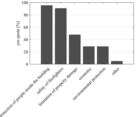
3.2 Fire safety goals . . . 23
3.3 Fire safety concepts and measures . . . 24
3.4 Verification for compartment fires . . . 25
viii CONTENTS
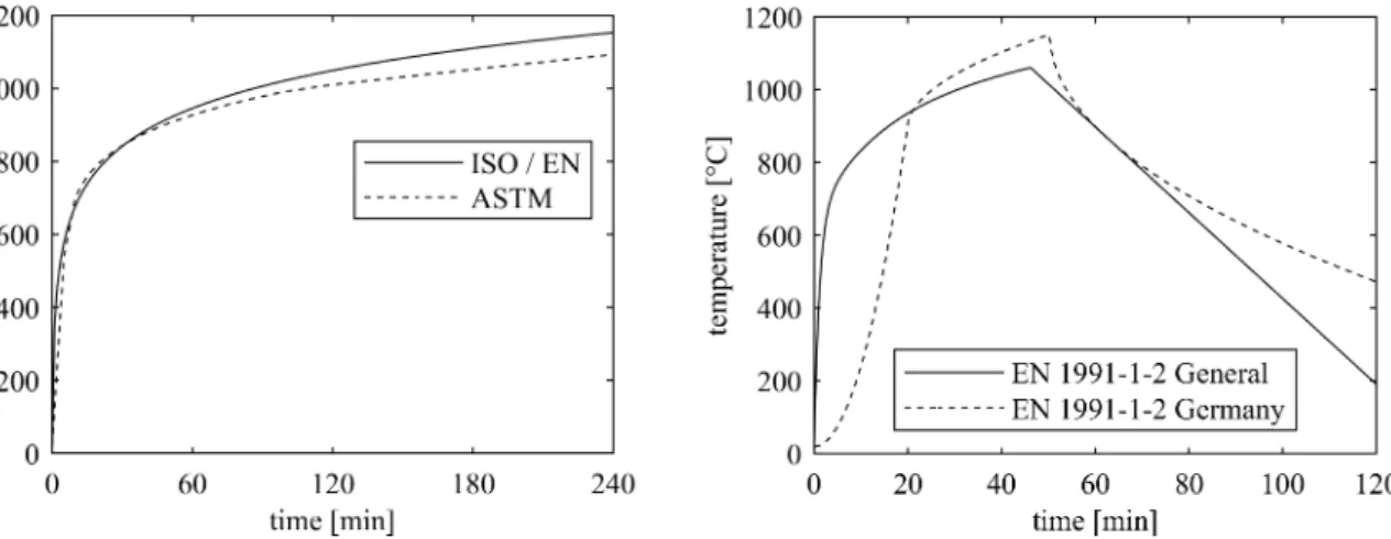
3.4.1 Nominal fires . . . 25
3.4.2 Physically based fires . . . 26
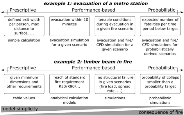
3.4.3 Verification methods . . . 29
3.4.3.1 Notes on terminology: prescriptive, performance-based and prob- abilistic . . . 29
3.4.3.2 Verification based on standard fire . . . 30
3.4.3.3 Verification based on physically based fires . . . 32
3.5 Summary and relevance for the code calibration . . . 33
4 Timber in fire 35 4.1 Behavior of timber in fire . . . 35
4.1.1 Timber exposed to heat . . . 35
4.1.2 Dependencies of the charring processes . . . 36
4.1.3 Temperature dependent thermal properties . . . 37
4.1.4 Structural resistance . . . 37
4.2 Effective cross section method . . . 38
4.3 Corner rounding model . . . 40
4.4 Summary and relevance for the code calibration . . . 41
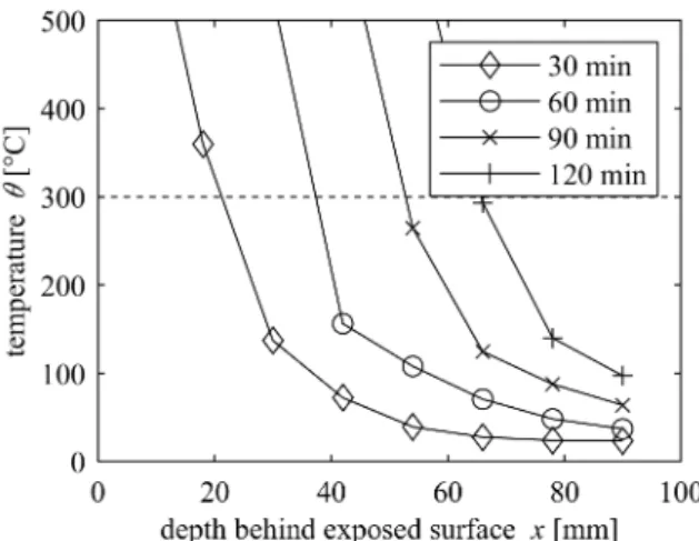
5 Simulations 43 5.1 1D charring according to EN 1995-1-2:2004 . . . 43
5.2 Reference simulations for beams exposed on three sides . . . 44
5.2.1 Aim . . . 44
5.2.2 Simulation . . . 44
5.2.2.1 General . . . 44
5.2.2.2 Thermal simulation . . . 46
5.2.2.3 Structural resistance simulation . . . 46
5.2.3 Fitting of the rounded corner model . . . 50
5.2.4 Comparison with the effective cross section method . . . 53
5.3 Reference simulations for beams exposed on the underside . . . 56
5.3.1 Aim . . . 56
5.3.2 Simulation . . . 56
5.3.2.1 General . . . 56
5.3.2.2 Thermal simulation . . . 57
5.3.2.3 Structural resistance simulation . . . 57
5.3.3 Derivation of the zero strength layerd0 . . . 57
5.4 Summary and relevance for the code calibration . . . 60
6 Calibration setup 61 6.1 Reference structures . . . 61
6.2 Code formats . . . 62
6.2.1 General . . . 62
CONTENTS ix
6.2.2 EN 1995-1-2:2004 code format . . . 63
6.2.3 Draft EN 1995-1-2:202x code format . . . 63
6.2.4 Extension of the Draft EN 1995-1-2:202x code format . . . 64
6.2.5 Loads according to Eurocode . . . 64
6.2.6 Strength according to Eurocode . . . 65
6.3 Reliability model . . . 65
6.3.1 Introduction . . . 65
6.3.2 Probability of a fully developed fire . . . 66
6.3.3 Limit state functions . . . 68
6.3.3.1 Permanent design situation . . . 68
6.3.3.2 Fire/accidental design situation . . . 68
6.3.4 Loads . . . 70
6.3.4.1 Permanent load . . . 70
6.3.4.2 Variable load . . . 70
6.3.4.3 Model uncertainty of the variable load . . . 76
6.3.5 Resistance . . . 78
6.3.5.1 Uncertainty of the strength . . . 78
6.3.5.2 Uncertainty of the charring process . . . 78
6.3.5.3 Model uncertainty of the resistance . . . 81
6.4 Calibration procedure . . . 82
6.4.1 General . . . 82
6.4.2 Monte Carlo Simulations in code calibrations . . . 83
6.4.2.1 General . . . 83
6.4.2.2 Design-based code calibration . . . 83
6.4.2.3 Reliability-based code calibration . . . 84
7 Calibrations and analyses 87 7.1 Main calibration for Draft EN 1995-1-2:202x . . . 87
7.2 Comparison between the claimed use of 5% fractiles, the status quo and the calibrated code format . . . 92
7.3 Analysis of the effect of inherent reliability differences . . . 94
7.4 Alternative code formats . . . 98
7.4.1 Unitary zero strength layer . . . 98
7.4.2 Exposure-dependent charring rate . . . 98
7.4.3 Results . . . 99
7.5 Influence of the chosen error term . . . 100
8 Summary and Conclusion 107 9 Extended Outlook 111 9.1 General Outlook . . . 111
9.2 Outlook on code calibrations for standard fire exposure . . . 111
x CONTENTS
9.3 Outlook on code calibrations for physically based fires . . . 113
9.3.1 Demand for physically based fires . . . 113
9.3.2 Physically based fires and advanced methods with timber as structural material . . . 114
9.3.3 Code calibration for physically based fires . . . 118
Appendices 121 A Reducing explicit structures to generic representations 121 A.1 Introduction . . . 121
A.2 General definition of the limit state function and the code format . . . 121
A.3 Generalized derivation for two applied loads . . . 122
A.4 Examples . . . 124
A.4.1 Problem statement . . . 124
A.4.2 Example 1: Two line loads . . . 124
A.4.3 Example 2: Line load and point load . . . 125
A.4.4 Example 3: Line load in bending . . . 126
B Section modulus of the corner rounding model 127
C USDFLD Program code 131
D Additional figures of the calibrations 135
Nomenclature 141
Glossary 147
Acronyms 151
References 153
List of tables 165
List of figures 167
Chapter 1
Introduction
1.1 Background and motivation
Timber as a construction material is booming for several reasons: Architects have discovered the pleasant atmosphere spread by visible structural timer. At the same time, new ways of timber construction were (and are) developed, so that modern timber constructions fulfill strict serviceability criteria. Furthermore, timber is probably the most industrialized construction material today, allowing precise prefabrication and a quick erection on site. It is a lightweight construction, reducing effort and costs for foundations. Probably the most important benefit of timber compared to other construction materials is found in ecology (Churkina et al. 2020):
Timber has a low carbon footprint and serves as a carbon storage. Additionally, contrary to concrete and steel, the complete process chain from harvesting to erection is independent of fossil fuels.
The current boom of timber construction can be seen as a comeback: Timber was banned from cities as a reaction to large city fires and replaced by non-combustible construction materials such as masonry or concrete. The research on the contribution of structural timber to a fire is still ongoing. Nevertheless, the use of timber as a construction material is permitted again, owed to standardized fire testing (Babrauskas and Williamson 1978a), fire spread prevention strategies such as compartmentation, increased construction quality and better fire suppression measures by the fire brigade and automatic sprinkler systems.
A quantum leap for fire safety was the introduction of standardized fire testing in 1918 (ASTM E119). Nearly the same standardized time-temperature curve is followed to this day (ISO 834-1:1999) and provides the basis for the most common design verification for the fire situation in Eurocode 5 (EN 1995-1-2:2004). Instead of performing a fire test for each planned construction, the code provides equations to verify the fire design analytically. An appropriate reliability level is thereby guaranteed by the applied partial factors and the choice of characteristic values for scattering properties such as loads and strength. The characteristic values are often
1
2 Chapter 1. Introduction
defined as a fractile1. The strength fractile is typically chosen as 5%, with the exemption of timber subjected to fire, where the 20% fractile is used. This contradiction dates back to the introduction of the partial factor design in Eurocode: The partial factors were calibrated so that the resulting designs were equivalent to preceding codes (König 2005). However, for the strength in fire, the partial factor was harmonized as one for all materials. The same effect as calibrating the partial factor was achieved by changing the fractile to 20%.
1.2 Problem and methodology
The following section gives a conceptual overview of the methodology. Previous knowledge about reliability analysis, code calibration and the structural design of timber in fire is required for its understanding. This information is introduced in detail in Chapters 2, 3 and 4.
The use of the 20% fractile for the strength of timber in fire was recently questioned, since it subjectively appears to be unconservative and might be an unjustified benefit for timber compared to other materials. The aim of this thesis is to investigate the influence of the fractile value on the homogeneity of the reliability levels of arbitrary structures, when designed according to the calibrated code. Therefore, reliability-based code calibrations for timber exposed to standard fire are conducted. The outcome of this dissertation will provide important input for the ongoing revision of the Eurocode 5 fire part (Draft EN 1995-1-2:202x).
Using a standard fire exposure implies a significantly biased reliability model, since important uncertainties of a fire such as the fire load density and the heat release rate are deemed to be covered in the deterministic fire resistance requirement. Therefore, the mean reliability index of the current Eurocode (EN 1990:2002, EN 1991-1-1:2002, EN 1995-1-1:2004) when applied to a set of representative reference structures is taken as the target reliability for the subsequent code calibrations. In such a relative code calibration (Section 2.3.2), the same bias appears in the derivation of the target reliability index as well as in the code calibration, whereby the bias roughly cancels out. Since the mean reliability index of a calibrated code format is generally not equal to the target, a special procedure to enforce their equality is introduced in (Section 2.3.3).
For the code calibration, the current code format for the fire design of timber structures (EN 1995-1-1:2004) is extended with a partial factor on the charring rate (Section 6.2.4), which
is advisable due to its high importance factor (Figure 7.2).
The limit state function for timber structures in fire unfortunately does not allow the usage of generic reference structures (Section 2.2.4). Therefore, explicit structures need to be defined.
Only simple beams are considered, since their simplicity allows the derivation of an accurate reliability model and because it probably is the most important structural element in timber engineering. By varying several properties (e.g. beam aspect ratio, length, loads), a large set of reference structures can be created (Table 6.1). Only structures where the accidental (i.e. fire)
1In engineering statistics, it is common to define a fractileϕof a certain percentagep, denoting the value of a distributed property which is exceeded with a probability of 1−p. In other fields the same would be called pth percentile.
1.2. Problem and methodology 3 load situation is decisive over the permanent design situation are finally considered. This can be evaluated with a reliability analysis for both situations (Section 6.1).
The reliability model should be as accurate as reasonably possible. To consider the shortcom- ings of the simplified code format for timber in fire, the reliability model for the resistance must be accurate in particular where the code format is not. The code format for beams in fire in Eurocode 5 (EN 1995-1-1:2004) is based on the effective cross section method (Section 4.2). Its main simplifications are a constant charring rate and zero strength layer as well as the neglect of the corner rounding. The same code also describes advanced methods, in particular the finite element method, which do not suffer from the shortcomings. However, for reasons of the computational effort, a reliability model is preferably based on analytical equations rather than simulations. Therefore, an enhancement of the effective cross section method considering the rounded corners, is developed (Section 4.3). This model is then fitted to match the resistances received in finite element simulations according to Eurocode 5 as close as possible (Sections 5.2.3 and 5.3.3).
The ultimate resistance of timber beams in fire is typically reached when the outermost finite elements have already failed, since those heated elements with low strength and stiffness contribute less to the resistance than cooler elements further inside can contribute additionally.
However, a material model including brittle behavior typically leads to difficulties in implicit finite element simulations. Thus, a unique material model is developed. The resistance is derived in two subsequent (i.e. uncoupled) simulations: First the thermal behavior is simulated, then the load is applied until failure (Section 5.2.2.3).
The aforementioned analytical resistance model is derived deterministically. Its main prop- erties are the strength and the charring depth. In the reliability model, both properties are considered as probabilistic. However, the probabilistic modeling of the charring depth is not found in literature so far. To provide the fundamentals to derive a probabilistic charring model, four fire resistance tests are conducted and evaluated (Section 6.3.5.2).
The probabilistic models for loads and the resistance at ambient conditions are mainly taken from literature. For the variable load modeling, an extensive literature review is carried out and the probabilistic models are derived by simulating and evaluating a time history of loading cycles (Section 6.3.4.2).
Finally, several relative code calibrations are conducted on the basis of the derived reliability models (Chapter 7). The main calibration of the adapted code format (Section 7.1) is conducted with the first order reliability method (FORM) as well as on the basis of Monte Carlo Simulations (MCS). The comparison of both methods shows whether the additional effort for MCS based reliability analysis is worth the gained accuracy. The inherent reliability differences among structures when designed with the calibrated code format are then analyzed with further calibrations on subsets of the reference structures (Section 7.3). The findings of this analysis are used for calibrations of optimized, alternative code formats (Section 7.4). For academic interest, the present code calibration is finally repeated with various error terms and its differences are highlighted (Section 7.5).
4 Chapter 1. Introduction
1.3 Outline
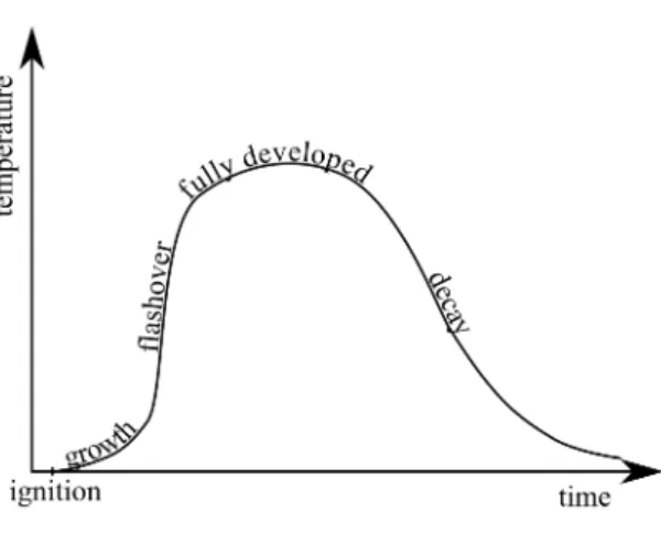
Since this thesis combines two special fields, reliability analysis and fire safety engineering, it provides an introduction of the relevant aspects of both fields. Chapter 2provides a brief outline about reliability analysis, followed by an in-depth introduction to code calibration and target reliability indices. Chapter 3 shortly discusses the typical development of a fire, followed by an introduction to fire safety goals and general concepts to reach those. Then, a closer look is given at verification methods for fire resistance. Additionally, a glossary with some of the most important terms is provided on page 147.
The behavior of timber exposed to heat and fire is discussed in Chapter 4. Furthermore, the fire resistance verification method implemented in EN 1995-1-2:2004 is explained. For the reliability analysis of beams exposed on the underside and the sides, a more accurate resistance model is required: The corner rounding model.
Both resistance reliability models used in the calibrations are fitted to simulations described inChapter 5. Furthermore, a comparison between the simulations and the verification method in EN 1995-1-2:2004 is provided.
Chapter 6 presents the setup of the calibrations, including the reference structures, the calibration procedure and the code formats according to Eurocode 5 (EN 1995-1-2:2004) or the draft of its successor (Draft EN 1995-1-2:202x), respectively. The reliability models and random distributions are discussed in detail.
To gain an in-depth understanding of the calibrated code format and the influence of the chosen fractile on the calibrated partial factors,Chapter 7 presents several reliability analyses and code calibrations. Based on the findings of those calibrations, alternative code formats are introduced and calibrated as well.
The herein presented code calibrations and reliability analysis are based on standard fire resistance, which introduces a significant bias. To calculate an unbiased reliability index, the reliability model would have to be based on physically based fires, where the uncertainties of a fire can be appropriately considered. However, there is a lack of knowledge when it comes to modeling timber exposed to physically based fires. This gap is highlighted inChapter 9 in an extended outlook. It is split into an outlook on code calibrations based on standard fire and the prerequisites for code calibrations based on physically based fires.
Chapter 2
Aspects of reliability analysis and code calibration
2.1 Reliability analysis
Historical structural codes were based on fundamental physics, such as the theory of structures, and experience. In antecedent and current structural design codes, both loadsS and resistance R are (and were) treated deterministically and the design z is chosen so that the margin M = zR−S ≥ 0. Thereby, in antecedent codes, resistance and load parameters taken into account were based on experience. However, both parameters are obviously of uncertain nature.
Against that background, reliability analysis was developed. It does not try to deterministically differentiate between safe and unsafe as codes did and do, but attempts to calculate the probability of failure given a design. Thereby, all uncertain parameters are taken into account as random variables. Using reliability analysis for structural design, the target is given in terms of a "socially acceptable" probability of failure (Hasofer and Lind 1974).
The probability of failure is obviously related to a reference period of time, i.e. the probability of failure in one year or in the lifetime of a structure (often 50 years). While the resistance might be considered as time independent, the probability distribution of the variable load is dependent on the chosen reference period. The analyses made in this thesis refer to a reference period of one year, unless stated otherwise.
Additionally, a reliability analysis can be performed on different scales, e.g. for a structural element such as a beam or column or for a full-scale structure. This thesis focuses on single structural elements, which is in line with calibrations made for Eurocode (Baravalle et al. 2017).
The effects of parallel and/or serial subelements that are important for the reliability of a full-scale structure are not in focus in this thesis.
In reliability analysis, the margin M is called limit state function g(X) and delimits the safe domain (g(X)≥0) from the failure domain (g(X) <0). Considering both the resistance and the load as random variables XR respectively XS, the limit state function is written as in
5
6 Chapter 2. Aspects of reliability analysis and code calibration
Fig. 2.1: Probability density of the resistancezR, the load S and its differencezR−S. The probability of failurepf corresponds to the shaded area.
Equation 2.1, whereas the limit state is given byg(X) = 0.
g(X) =zXR−XS (2.1)
The probability of failure pf is then the probability thatg(x)<0 (Figure 2.1). For analytically simple problems with normal distributed resistanceXR∼ N(µR, σR) and loadXS ∼ N(µS, σS), the limit state function can be analytically determined, since the limit state function is also normal distributed with:
µ=µR−µS (2.2)
σ=qσ2R−σS2 (2.3)
The probability of failurepf is given through the normal cumulative distribution function (Φ) (Equation 2.4). By expressing the distance of the mean of the limit state function from the failure domain as a multiple of the standard deviation (µ= βCoσ), Cornells definition of the reliability indexβCo (Cornell 1967) is found:
pf = Φ0−µ σ
def
= Φ(−βCo) (2.4)
As an approximation method, it was suggested by Cornell (1967) to use the above combination of the first two moments (Equations 2.2 and 2.3) also for non-normal distributed loads and resistances. The method was later referred to as first order second moment (FOSM). However, this method was not invariant to transformations of the limit state function. (e.g.g(x) =R−S would not give the same result as g(x) =ln(R)−ln(S), despite the fact that the limit state g(x) = 0 holds for both cases.)
Hasofer and Lind (1974) generalized Cornells approach. By transforming all random parame- ters into standard normal distributions, and the understanding that the reliability index β is the shortest distance between the origin of the multi-dimensional space formed by the different standard normal distributions and the surface defined by the limit state function, the first order
2.2. Code calibration 7 reliability method (FORM) solved the lack of invariance. In the FORM, the limit state function is linearly (i.e. first order) approximated. Second order approximations (SORM) were developed later e.g. by Hohenbichler et al. (1987), Breitung (1989), Tvedt (1990) and Cai and Elishakoff (1994). Both the FORM and the SORM use the same relationship between reliability indexβ
and the probability of failure pf as the FOSM method:
pf = Φ(−β) (2.5)
Nowadays, the computational power allows the numerical computation of the failure prob- ability using Monte Carlo Simulations (MCS) (e.g. Rubinstein and Kroese 2016). Thereby, n random sample values are generated for every uncertain property. Subsequently, the limit state function g(x) is evaluated for every set of random samples and the number of samples where the limit state function indicated failure, i.e. g(x)<0, is counted (nf). The probability of failurepf
can then be calculated by:
pf = nf
n (2.6)
Since the probability of failure is usually small, a high number of samples must be computed to reach a certain confidence of the probability of failure. Thus, the method is still computationally costly and especially in code calibration, where many reliability analyses must be performed, the FORM still has its justification.
2.2 Code calibration
Some paragraphs in this section are based on Fahrni et al. 2021.
2.2.1 General
A calibrated code is a compromise between the maximization of safety and the minimization of construction costs, while keeping the code format simple to avoid unnecessary complexity and errors in its application. Calibration is the process to find the optimum.
2.2.2 Levels of code calibration
Code calibration as well as design verification can be done based on four different complexity levels (Baravalle 2017, Ferry Borges 1976, ISO 2394:2015, Melchers and Beck 2017), of which two are reliability related:
Level 4 Risk-informed approach
Level 3 General reliability-based approach (e.g. FORM (Hasofer and Lind 1974), MCS) Level 2 Simplified reliability-based approach (e.g. FOSM, Cornell 1967)
Level 1 Semi-probabilistic approach
8 Chapter 2. Aspects of reliability analysis and code calibration
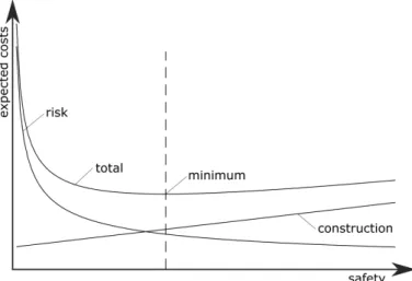
Fig. 2.2: Level 4 cost optimization (schematically). Commonly, the safety level at minimum total cost is expressed in terms of a reliability index and is used for level 3 calibrations or as a design target.
Level 4 provides the balancing between safety and construction costs by minimizing the total expected costs of a building (e.g. Rackwitz 2000). Simplified, the total costs consist of the construction costs and the costs associated with a failure and its probability, i.e. the risk.
With increasing safety level, the probability of failure of a structure and thus also the risk reduces roughly inversely proportional, while the construction costs increase approximately linearly (Figure 2.2). The probability of failure is assessed in a reliability analysis and strictly monotonically decreases with increasing safety. Thus, the optimum level of safety, i.e. where the total costs are minimum, can also be expressed through the probability of failurepf or the reliability indexβ respectively.
Basically, any design could be optimized based on a level 4 cost optimization. However, this would be cumbersome for practical application, as a probabilistic risk based analysis was required.
Thus, optimal reliability indices were derived for certain consequence classes and relative costs of safety measures (e.g. JCSS 1). These reliability indices are targets for design verification on levels 2 and 3, where the reliability index of the structure is required to be higher than or equal to the target reliability index. Level 2 reliability analyses (e.g. FOSM, Cornell 1967) are basically of historical interest, since more general and accurate level 3 methods are available.
Even if level 3 methods are available in modern software, its use would still be too cumbersome for the daily practice of structural engineers. Thus, modern codes use a semi-probabilistic code format (level 1), e.g. "load and resistance factor design" (Hansell 1978) or "partial factor design"
(Ferry Borges 1976) as used in the Eurocodes (EN 1990:2002). They intend to guarantee a sufficient reliability level by introducing safety factors and the use of fractile values on uncertain parameters such as the strength or loads.
As any design verification method on a certain level is a simplification compared to higher level methods, accordingly designed structures are generally not optimal with respect to higher level targets. Therefore, a code calibration of a lower-level code format is an optimization so that corresponding designs will deviate as little as possible from the target set on the higher level. For
2.2. Code calibration 9 the general applicability of the code format, the calibration process aims at the homogenization of the safety level among a set of reference structures ithat are within the scope of the code.
Thus, a code format is usually calibrated by the minimization of a error term E through the variation of the calibratable factors (Equation 2.7). This thesis focuses on the semi-probabilistic code format (level 1) of the Eurocodes (EN 1990:2002) and calibratable factors are denoted
"partial factors" γj.
γj = arg min
γj (E(γj)) (2.7)
The error term E is defined in terms of the level, against which the code format is calibrated.
Semi-probabilistic code formats (level 1) are probably most commonly calibrated against a target reliability indexβt (level 3). The error termE thereby can be defined as shown in Equation 2.8, where βi(γj) denotes the reliability index reached with the given set of partial factorsγj for the reference structure i.
E=X
i
(βi(γj)−βt)2 (2.8)
Conversely to a reliability-based (Equation 2.8) calibration, the Eurocode (as stated in EN 1990:2002 (C4.4)), especially also the timber in fire part (EN 1995-1-2:2004), were calibrated against antecedent codes. Thereby, the error term was specified in terms of the design variable z, a geometrical property, which for example is the section modulus for a beam in bending or the cross section for a (stocky) column in compression. Such a calibration is referred to as design-based calibration (Fahrni et al. 2021). Trying to assign a complexity level to such a calibration in aforementioned scheme, level 0 might be appropriate. As also in a design-based code calibration a perfect match of the target designszi,t is impossible for the whole scope of the code, an optimization is needed. In contrast to Equation 2.8, the targets in a design-based calibration are structure specific. Thus, an additional divisor is needed to normalize the deviation of each structure, so that there is no inadvertent weighting by the design (e.g. geometry) of a structure (Equation 2.9). In a calibration against an antecedent code, zi,t =zi,old code.
E =X
i
zi(γj)−zi,t
zi,t
2
(2.9) Please note that in all the error term definitions above, deviations from the target are treated symmetrically, i.e. a deviation on the unsafe side (i.e. a negative deviation) is weighted the same as a deviation on the safe side (positive). Whether this is reasonable or whether negative deviations should be additionally penalized, can be discussed controversially and also depends on the error term used. This is followed up in Section 7.5, providing an exemplary comparison between different error terms applied to the main calibrations presented herein. Further error terms can be found in Baravalle (2017) (Appendix A).
2.2.3 Calibration procedures for reliability-based targets
In this thesis, a reliability-based code calibration is performed. Two different procedures exist (Fahrni et al. 2021): (1) The common reliability-based code calibration and (2) the design-based
10 Chapter 2. Aspects of reliability analysis and code calibration
code calibration with reliability-based targets. After an introduction to the basic calibration components, both procedures and their benefits and drawbacks are explained in the following sections.
An important difference between a design-based (level 0) calibration (as mentioned above) and a reliability- or risk-based calibration (level 3 or 4, respectively) is the error term, i.e.
the comparison with the target: In reliability- or risk-based calibrations (level 3 and 4), the comparison requires the calculation of each structure’s reliability index in every error term minimization iteration, whereas this is not required in a level 0 calibration. Since a reliability analysis is computationally costly, a level 0 calibration is significantly faster than a calibration against a reliability or even risk target.
2.2.3.1 Calibration components
The code calibration process towards reliability-based targets can be split into three components:
(The colors and border line styles noted in parenthesis are used in Figures 2.3 and 2.4 to differentiate the components.)
i) Code calibration (blue, solid)
The code calibration is the main component and interacts with the other two (sub-) components, i.e. the code format and the reliability analysis. The first step is to define the target reliability index and the scope of the calibration.
The calibration is executed for a set of reference structures (followed up in Section 2.2.4) that shall represent the scope of the code format. Each reference structure must define the properties that are needed in the limit state function(s). The actual calibration is the minimization of the measure of closeness, i.e. the error term (e.g. Equations 2.8, 2.9) by adapting the partial factors. Obviously, in each iteration, the code format is evaluated for every reference structure i.
Finally, it is important to analyze the remaining reliability deviations of the reference structures in order to recognize excessive or systematic deviations. As every deviation is the result of the simplification made in the code formats, this analysis could detect oversimplifications, which should be alleviated by either a reduced scope of the code format or by adjusting it.
ii) Code format (green, dashed)
The code format defines the format for verification of each type of reference structure, that means it also defines which fractiles of the random parameters are used, which partial factors exist and how/where they are applied. During the calibration, the code format is used to calculate the necessary design zi (i.e. the geometry) for a given reference structure, so that the verification is exactly met with a given set of partial factors. The design is typically represented by the geometry of the structural member.
iii) Reliability analysis (pink, dotted)
The reliability analysis assesses the reliability indexβi of a certain reference structure for
2.2. Code calibration 11
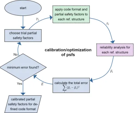
Fig. 2.3: Reliability-based code calibration flow chart. Color and line style identify the three different components of the process: calibration (blue, solid), code format (green, dashed), reliability analysis (purple, dotted). The whole calibration process takes place in one iterative optimization.
a given design zi. For each type of structure, a reliability model consisting of the limit state function and the probabilistic distributions must be defined. It is important that the reliability model does not only cover the aleatoric and epistemic uncertainties of each parameter, but also a term for the model uncertainty (JCSS 3.09). The reliability index βi of each reference structure is finally assessed with a reliability method such as FORM (Hasofer and Lind 1974) or MCS (e.g. Rubinstein and Kroese 2016).
All three components are used in both calibration procedures. The difference lies in the call sequence, as shown next.
2.2.3.2 Procedure 1: Common reliability-based code calibration
Figure 2.3 shows a flow chart of the calibration procedure in the commonly used reliability-based code calibration (e.g. Faber and Sørensen 2003, Melchers and Beck 2017). Initially, the reference structures, the target reliability index, the code format as well es the reliability models must be defined. Then the actual calibration, i.e. the iterative optimization of the partial factors, begins with an initial guess of the latter. Then each reference structure is designed according to the code format using the chosen partial factors γj. After, the reliability index of each structure given that design zi is assessed and finally, the deviation between the reliability indices and the target, i.e. the error term, is calculated. By changing the partial factors in each iteration, the error term is minimized and the optimum partial factors can be found.
12 Chapter 2. Aspects of reliability analysis and code calibration
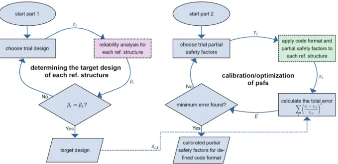
Fig. 2.4: Design-based code calibration with reliability-based targets flow chart. Color and line style identify the three different components of the process: calibration (blue, solid), code format (green, dashed), reliability analysis (purple, dotted). Part 1 (left) translates the reliability-based target reliability index into a geometrical target for each reference structure and involves probabilistic reliability analysis.
Part 2 (right) is the design-based calibration of the code format.
Defining the error term directly in terms of the reliability index (Equation 2.8) is preferred over a definition based on the design (Equation 2.9), since it directly follows the aim of code calibration to reduce the reliability scatter among the reference structures. However, its drawback is the computational effort: In every iteration, a computationally costly reliability analysis must be performed for every structure.
2.2.3.3 Procedure 2: Design-based code calibration with reliability-based targets The intention of this calibration procedure is to combine the computationally fast code calibration of design-based optimization (Equation 2.9) with a reliability-based target. Therefore, the target reliability index has to be translated into a target design first, before the actual calibration can be done design-based. Figure 2.4 shows this process on the left (part 1). It bases on the idea that for each reference structure there is a designzi corresponding to a target reliability index βt. Unfortunately, deriving the necessary structural design for a given target reliability index is in general not directly possible, as the calculation of the reliability index is typically1 a one-way function, i.e. the reliability index can be calculated for a certain design, but not vice versa. Thus, after having defined the target reliability index, the reference structures and the reliability model, the design associated with the target reliability (zi,t) must be found iteratively.
That means, in every iteration the reliability index is assessed for a given trial design zi until
1With the introduction of the inverse FORM (Der Kiureghian et al. 1994), the direct derivation of the target design got possible for FORM based reliability analysis. However, MCS (-based) reliability analyses are naturally not invertible.
2.2. Code calibration 13 the resulting reliability index matches the target. This root-finding problem is solved for every reference structure and typically takes less than 7 iterations (Fahrni et al. 2021). Since this procedure involves repeated reliability analysis, it is computationally costly.
As soon as the target designs are derived, the actual calibration of the partial factors can be done (Figure 2.4, part 2). The minimization of the error term now only involves the evaluation of the code format. Thanks to this decoupling of code format and reliability analysis, the actual calibration now is computationally fast and runs within a few seconds. Since the derivation of the target designs requires significantly less iterations than the calibration optimization, the number of computationally costly reliability analysis is reduced and the total required time is significantly lower than in a reliability-based calibration (Fahrni et al. 2021).
The design-based code calibration with reliability-based targets is computationally even more beneficial when it comes to code format optimizations, since no reliability analyses must be redone in a subsequent calibration with a different code format. However, the drawback of design-based code calibrations is that the optimization, i.e. the error term, is not defined in terms of the reliability index. Despite the fact that both error terms are identical at the optimum, the difference introduces a bias which increases with the deviation from the target.
In an exemplary calibration for the purpose of comparison (Fahrni et al. 2021) this lead to larger maximum reliability index deviations in the design-based code calibration compared to the reliability-based. Additionally, the calibration showed that this might also lead to a significant difference between the resulting mean reliability index (over all reference structures) and the target reliability index. In a reliability-based calibration, the mean and target reliability indices differ as well, but significantly less. This is followed up in Section 2.3.3, describing an approach to eliminate this difference.
Especially due to the difference between the mean and the target reliability index, also the resulting calibrated partial factors may differ significantly. These problems might be the reason, why the literature mostly follows the common reliability-based code calibration (e.g. Sørensen et al. 1994, Melchers and Beck 2017, ISO 2394:2015). Nevertheless, design-based calibrations with reliability-targets are found in some of the first code calibrations (Ellingwood 1978, Ellingwood et al. 1980, Ellingwood et al. 1982).
The design-based code calibration is most useful for code format optimizations, since the deviations in the mean reliability index and in the calibrated partial factors can both be considered as a constant shift. Therefore, the conclusion drawn about the appropriateness of a code format given the set of reference structures and its further improvement is independent of the calibration procedure used. The design-based calibration procedure is thus suggested for code format optimizations, whereas the final calibration of the code format should be done reliability-based.
2.2.4 Choosing reference structures
For code calibrations, the use of generic reference structures is beneficial. It allows to reduce the number of considered structures, by exploiting the analytical equivalency of some property variations (followed up in Appendix A). For example, the reliability index often does not change
14 Chapter 2. Aspects of reliability analysis and code calibration
when e.g. the strength class of the material is changed, as long as the CoV and the probability distribution stay the same.
Generic structures are represented by normalized properties instead of absolute values for mean and standard deviation. In the reliability model, the information about the scatter of properties is given by the CoV and the distribution type, while the mean value is one. In the code format, the fractile values are in turn represented by the conversion factor between the mean and fractile value of the respective distribution. Given the generic distributions for the loads and the resistance, different structures are modeled by the variation of one or a few dimensionless parameters, defining a ratio between the different loads. Thereby, this parameter does not only cover truly different load ratios (e.g. Baravalle 2017, De Sanctis 2015, Köhler and Fink 2012), but also different types of load combinations (e.g. bending and compression or the combination of a point load and a distributed load on a beam) and structure geometries. Hence, different load ratios and combinations can be modeled by varying one or very few parameters.
Therefore, a vast number of structures can be represented by a few variations of the same generic structure, reducing the number of effectively required reference structures significantly.
Appendix A analytically shows how different load combinations and absolute strengths can be represented by the same generic structure.
For many explicitly defined structures, the analytical reduction to a generic representation is possible. However, some structures, e.g. those involving nonlinear reliability models, cannot be reduced to generic structures. This also applies to timber in fire.
2.3 Target reliability index
2.3.1 Absolute target reliability index
An absolute target reliability index is derived from a cost optimization, as shown in Sec- tion 2.2.2/Figure 2.2. To generalize this structure or building specific optimum, target reliability indices can be derived dependent on the relative costs of safety measures and the consequences of a failure (e.g. JCSS 1, ISO 2394:2015). However, the derivation was actually made for the ultimate limit state of structural elements and not for the fire situation. Hopkin et al. (2017) investigated the reliability level of steel structures designed with parametric fires after Eurocode (DIN EN 1991-1-2/NA:2015, EN 1993-1-2:2005). He showed that the resulting reliability indices are consistent with the values given in JCSS 1. Additionally, Hopkin et al. (2017) pointed out that targets for evacuation and the structural resistance must be differentiated. Basically, the failure costs should also include the loss of human lives. This naturally is ethically difficult. An objective measure to incorporate human lives is the societal willingness to pay (SWTP), which defines a lower limit for the target reliability index. It can be derived from the life quality index (LQI, Nathwani et al. 1997, Fischer et al. 2012a). Thereby, the assignment of a monetary value
to life is avoided (Fischer et al. 2019).
2.3. Target reliability index 15
A derivation of the target reliability index via cost optimization assumes that the true probability of failure can be assessed. However, calculated probabilities of failure cannot be validated and thus lack a scientific status (Popper 2002, Melchers and Beck 2017). On the contrary, the typical failure rates of buildings appear to be significantly below the targeted probability of failure. Additionally, all to the author known structural failures are due to design or execution errors or due to lack of inspection and maintenance (e.g. Dietsch and Winter 2018). However, within reliability analysis, such human failure is typically not included, despite the fact this would be required due to its predominant effect on the true probability of failure.
Apart of the mentioned lack of human failure consideration in reliability analysis, the following causes (among others) may bias the reliability analysis:
• Tail fitting: Since the target probability of failure is low, failure occurs only when all uncertain parameters take unfavorable values. These unfavorable values appear in the tails of a distribution. This means that for accurately calculating the probability of failure, a well fitted tail is important. However, this would require a vast amount of statistical data, which might be hardly available.
• Tail shape: Additionally, the shape of the tails is important. Distributions typically are defined over the range from negative infinity or zero to positive infinity, which in reality is hardly realistic. There might be a (high) natural maximum for loads as well as there might be natural minimum for resistances. For resistances, such a minimum resistance could be the load that appeared during construction before an element is finally put in place. For prefabricated elements, this kind of proof load can be high or even be decisive for the design.
Massini (2019) analyzed the effect of the distribution boundaries. Therefore, he truncated the probability distribution at certain fractiles of the actual distribution. Apart of the chosen fractile, the effect of truncation obviously also depends on the distributions and the CoV of the non-truncated distributions. As a representative example, a truncation of 1‰ of the variable loads upper tail resulted in a reduction of the probability of failure by factor three (βref = 4.14, β99.9= 4.4), while truncating 1% reduced thePf by factor 47 (β99 = 4.95).
• Scale dependency and robustness: In a robust design, a local failure should not lead to large consequences and especially not to consequences/failure on a larger scale (Voulpiotis et al. 2021). However, this means that in a robust design the consequences are lower and therefore the target reliability index would strictly speaking have to be lower as well.
• Human intervention in overload situations: As stated before, failure hardly occurs when the resistance and the loads do not take unfavorable values. At the same time, an About calculating the "true probability of failure"
16 Chapter 2. Aspects of reliability analysis and code calibration
overload situation can sometimes be detected by humans and counter measures are initiated. In regions with significant snow fall, this load situation is often decisive for the roof design. The loads according to the code are based on the local probability of a certain snow load and can be derived from long term snow fall measurements. The CoV of snow load is typically high, e.g. 40% (Baravalle 2017) and thus also the tails are pronounced. However, in winters with high snow fall, where reaching the failure state gets probable, people often will start to remove snow from their roofs. If this shall be represented in the probability distribution, it would mean a cutoff in the tail (knowing the snow will be removed) or a reduction of the tails size. However, if the human intervention is not accounted for in the uncertainty model for snow loads, the resulting reliability will be conservative compared to the "true" reliability.
• Intentional overdesign: A structure is hardly designed to meet exactly the requirements in the code, but will be slightly overdesigned, e.g. since defining the resistance is often bound to non-continuous steps or because there shall be reserves for future changes of use. Thus, the calculative probability of failure in real buildings is typically lower than the targeted one.
• Overdesign by simplification: Simplification, mostly on the conservative side, is a typical part of the engineering design process. For example, as the name implies, non-load bearing structures are not considered for the resistance. Clamping effects of supports are often neglected as well, especially when they would be difficult to quantify. The same applies to plasticity, despite the fact it may impact the reliability significantly (Xiao and Mahadevan 1994).
Based on the mentioned weaknesses or simplification made within the reliability model, it can be concluded that a real probability of failure cannot be calculated. Thus, reliability analysis and reliability indices should be treated as an engineering tool respectively an engineering quantity (Melchers and Beck 2017). In the spirit of the extended quote by Box (1976), "All models are wrong, but some are useful", reliability analysis has proven to be useful. Despite the strong simplifications and the fact that the actually prevalent failure mechanism (human error) is not treated in reliability analysis, the resulting reliability indices match the cost optimal targets surprisingly well (e.g. Baravalle 2017, Markova et al. 2018).
2.3.2 Relative target reliability index
A relative reliability target is consistent with the consideration of reliability analysis as an engineering approach. The target is thereby not derived from an objective and absolute higher level target, but from existing structures. Hence, the mentioned calibration of Eurocode (EN 1990:2002, Section 2.2.2) was a relative calibration, however based on the design and not reliability- based. A relative target reliability index can be derived as the mean reliability index of structures that are "socially accepted" (Hasofer and Lind 1974) and deemed to satisfy the societal demand
2.3. Target reliability index 17 for safety. An important benefit of relative reliability targets is that biases in the reliability model cancel out to a certain extent (Fahrni et al. 2019), when the same models are used in the derivation of the relative target as well as in the code calibration. Despite the fact that model biases cancel out to some extent, it is important to note that the reliability model must include all uncertain parameters with an appropriate probability distribution. If the same model cannot be used, e.g. because a new kind of structure (i.e. limit state function/code format) shall be calibrated towards other kinds of structures, the level of crudeness of all involved reliability models should be of comparable crudeness (Elms 1992).
2.3.3 Difference between target and mean reliability index
Intuitively, it could be expected that the mean reliability index over all calibrated structures is equal to the target reliability index. However, in general, the partial factors that lead to the minimum error term do not result in the mean reliability index being equal to the target.
Nevertheless, the difference is often small for reliability-based code calibrations (Equation 2.7), where the error term E is defined as in Equation 2.8. Equation 2.10 shows the optimization problem to be solved in those cases. The reason for the typically small difference is the analogy to Equation 2.11, which shows an untypical formulation how the mean value ¯x of a sample with valuesxi can be calculated.
γj= arg min
γj
X
i
(βi(γj)−βt)2
!
(2.10)
¯
x= arg min
¯x
X
i
(xi−x¯)2
!
(2.11) Thus, if Equation 2.10 was completely equivalent to Equation 2.11, the resulting mean reliability index would indeed be the target reliability index. However, the difference between the Equations is the term that gets optimized: In Equation 2.11 the scalar, second term is optimized2, while in the code calibration (Equation 2.10) the first term, i.e. the reliability index of each structure for the given partial factor(s) is optimized. Since the equations are similar, the difference between the target and the resulting mean reliability index is often small, but not zero, given the error term definition in Equation 2.8. For other error term definitions and especially for design-based code calibrations a higher difference between the target and calibrated mean reliability index must be expected.
Differences between the target and the mean reliability index contradict the concepts of both relative and absolute reliability targets, but seems to be more problematic with relative reliability targets. To avoid the difference, several methods are possible:
1. The requirement that the mean and the target reliability index shall be the same (βmean =βt) is an additional constraint that needs to be considered in the optimization. Probably the most obvious approach is the use of optimization algorithms that allow to define constraints
2An optimization is here actually not needed, since the derivative can be calculated and must be zero for the minimum error.