U
NIVERSITY OFR
EGENSBURGDOCTORAL THESIS
Musculoskeletal modelling of the shoulder complex and its application
for EMG assessed pathologies
Author:
Maximilian AURBACH
Supervisor:
Prof.Dr.-Ing. Sebastian DENDORFER
A thesis submitted in fulfilment of the requirements for the degree of Dr. scientiarum humanarum (Dr. sc. hum.)
at the
Faculty of Medicine University of Regensburg
conducted in the
Laboratory for Biomechanics OTH Regensburg
submitted by
Maximilian Aurbach, M.Sc.
July 2020
Dean Prof. Dr. Dirk Hellwig
Supervisor Prof. Dr.-Ing. Sebastian Dendorfer Mentors Prof. Dr. med. Tobias Renkawitz
Prof. Dr. Rainer Spang
Declaration of Authorship
I, Maximilian AURBACH, born at the 23.01.1990 in Heilbronn declare that this thesis titled, “Musculoskeletal modelling of the shoulder complex and its application for EMG assessed pathologies” and the work presented in it are my own. I confirm that:
• This work was done wholly or mainly while in candidature for a research de- gree at this University.
• Where any part of this thesis has previously been submitted for a degree or any other qualification at this University or any other institution, this has been clearly stated.
• Where I have consulted the published work of others, this is always clearly attributed.
• Where I have quoted from the work of others, the source is always given. With the exception of such quotations, this thesis is entirely my own work. I did not receive paid help from mediation and advisory services e.g. PhD consultants.
• I have acknowledged all main sources of help.
• Where the thesis is based on work done by myself jointly with others, I have made clear exactly what was done by others and what I have contributed my- self.
Signed:
Date:
“If I have seen further it is by standing on the shoulders of Giants.”
Isaac Newton
“But I am very poorly today & very stupid & I hate everybody & everything. One lives only to make blunders.”
Charles Darwin
Abstract
The aim and purpose of the presented thesis is with regard to musculoskeletal model improvements of the human shoulder and simulation of pathologies. It ad- dresses three distinct research questions. From a modelling perspective using an in- verse dynamics approach, there is a discrepancy between computed glenohumeral joint reaction forces and in-vivo measurements above 90° humeral abduction. In- vivo measurements and muscle activities derived from electromyographic measure- ments indicate a continuous increase in the joint reaction force above 90° abduction.
Models using an inverse dynamics approach however tend to compute decreasing forces above 90° abduction. In order to address this issue, several modelling pa- rameters are tested and compared with regard to their effect on muscle activation and force development in the glenohumeral joint. Two clinical research questions are addressed and simulated with an updated model. The first investigates several operative techniques of a long biceps tendon transposition from a biomechanical perspective. As multiple techniques are used in the clinical practice, it is of inter- est how they compare in terms of joint reaction forces and whether one technique provides an outcome which is closer to the healthy state of the shoulder-arm com- plex. The second simulates tears of the m. supraspinatus and evaluates muscle recruitment changes, changes of the joint reaction forces and a comparison to elec- tromyographic measurements. This is done in order to assess, how model predic- tions compare to observations in the clinical field and whether a generic model can predict these changes. The major outcomes of this thesis are threefold: it postulates the mechanical muscle properties Hill muscle model as key parameter for the force development in the glenohumeral joint during abduction, argues for an insertion of the long biceps tendon at the bicipital groove as superior operative technique from a biomechanical point of view and depicts a discrepancy between simulated symp- tomatic cases of a tear of the m. supraspinatus with regard to electromyographic measurements.
Zusammenfassung
Die Kernaspekte der vorliegenden Dissertation fokussieren sich auf die musku- loskeletalle Modellierung und Simulation von Pathologien des menschlichen Schul- terkomplexes. Die Arbeit adressiert innerhalb dieses Kontextes drei spezifische For- schungsfragen. Auf der Simulationsebene wurde die Muskelrekrutierung des Schul- terkomplexes und die Kraftentwicklung innerhalb des Glenohumeralgelenks bei der Abduktion des Humerus untersucht. In-vivo Messungen basierend auf instru- mentalisierten Endoprothesen des Humeruskopfes zeigen einen kontinuierlichen Anstieg der resultierenden Reaktionskraft im Glenohumeralgelenk bis zu 150° Ab- duktion. Eine hohe Aktivierung der involvierten Muskulatur bei der Abduktion über 90° wird ebenfalls durch elektromyographische Messungen bestätigt. Mus- kuloskelettale Modelle der Schulter, welche auf einem inversdynamischen Ansatz beruhen, berechnen jedoch zumeist sinkende Muskelaktivitäten und damit verbun- den erniedrigte Gelenkreaktionskräfte. Um dieser Diskrepanz nachzugehen, wur- den mehrere kinematische, kinetische und Muskelmodell Parameter auf ihre Aus- wirkung bezüglich Muskelaktivität und Gelenkreaktionskraft evaluiert und mit ex- perimentellen elektromyographischen Messungen und der Literatur verglichen. Fer- ner wurde der Muskelfaserverlauf der anterioren, lateralen und posterioren Deltoi- den mittels virtueller Torus-Objekte innerhalb des verwendeten Schultermodelles für die Abduktion optimiert. Die erste der beiden klinischen Fragestellungen der dargelegten Arbeit bezieht sich auf eine Transposition der langen Bizepssehne. Meh- rere verschiedene tenodese Techniken oder eine Tenotomie finden hierbei im klini- schen Alltag Anwendung. Eine Untersuchung bezüglich biomechanischer Aspekte der unterschiedlichen Techniken ermöglicht hierbei Einblicke, welche am ehesten dem Normalzustand im Bezug auf Gelenkskraftentwicklung entspricht. Zwei teno- dese Techniken und die Tenotomy wurden hierbei während der Ellbogenflexion, Pronation und einer kombinierten Bewegung simuliert, wobei die Reaktionskräfte und Momente im Schulter und Ellenbogengelenk mit einem intakten Modell vergli- chen wurden. Die zweite klinische Anwendung betrifft eine Ruptur des m. supra- spinatus. Die Kinematik und Muskelaktivität gesunder und pathologischer Proban- den wurden hierbei experimentell bei 6 verschiedenen Bewegungen gemessen. Die
Probanden wurden in Simulationsmodellen mit und ohne Riss des m. supraspina- tus nachgebildet. Hierbei sollte ermittelt werden, ob ein generisches Modell Mus- kelrekrutierungsänderungen aufgrund eine Ruptur adäquat abbilden kann. Auf Si- mulationsebene konnte die Arbeit die mechanischen Eigenschaften des Hill Mus- kelmodelles als mögliche physiologische Ursache und Erklärung für die steigen- den Reaktionskräfte im Glenohumeralgelenk bei Abduktion >90° identifizieren. Im Bezug auf die biomechanischen Auswirkungen verschiedener tenodese Techniken der langen Bizepssehne scheint eine Verankerung an der Bicipitalrille aus mecha- nischer Sicht am ehesten die Kräfte des gesunden Modelles zu erzeugen. Dies liegt an der Präservation der generellen Richtung des Hebelarmes des langen Bizeps.
Der Vergleich zwischen modellierten Aktivitäten mit und ohne Ruptur des m. su- praspinatus konnte keine Übereinstimmung der simulierten und experimentellen Unterschiede bei symptomatischen Patienten zeigen. Dies wird auf eine eventuelle Veränderung der Kinematik der Scapula zurückgeführt, welche nicht im verwen- deten Modell Berücksichtigt wird. Die Erkenntnisse könnten jedoch für asympto- matische Rupturen gültig sein. Hierbei ist die Aussage, das die Änderung in der Muskelrekrutierung nur geringfügig ist, jedoch die Kumulative Erhöhung signifi- kante Auswirkung auf die Gelenkreaktionskraft hat.
Acknowledgements
First and foremost I would like to thank my supervisor Sebastian Dendorfer. His profound knowledge, demeanour, guidance and humour have inspired me for al- most 10 years. I could not have wished for a better mentor and role model. A similar position is occupied by his right-hand man, Franz Süß. His serenity, critical thinking and comprehensive skill-set always were a tremendous help and example.
Special thanks also go to Lars Krenkel for the entertaining, constructive discussion rounds and all-round knowledge. My colleagues Simon Auer, Simon Groß, Clemens Birkenmaier, Bernd Gamisch and Melina Tauwald deserve extra credits. The years spent together in hardship and laughter forged friendships which I will always cher- ish. A special place among these friends has Maximilian Melzner. I cannot thank him enough for his friendship, tremendous support and the awesome time together.
Also thanks a lot to all for investing your time in the proofreading. Furthermore, I want to thank the Regensburg Centre of Biomedical Engineering in general and more specific Alexander Leis for providing the organisational framework for this work and giving the best support in all administrative questions. Special acknowl- edgements also receive all the student assistants which helped in the measurements and various aspects of this work during the years. Their eagerness to learn, enthu- siasm and also frustration always made me remember why I started on this path in the first place. The contents of this thesis were created within the framework of the Interreg V, Project 38 by the EFRE, ZIEL-ETZ BY-CZ 2014-2020. In this context I want to thank my clinical and Czech project partners for the years of collaboration. I also received financial support by the Bavarian Academic Forum (BayWISS) – Doc- toral Consortium “Health Research”, which enabled me to participate in various conferences and visit other research centres. For this I am really grateful, as these experiences were an integral part of my education. I furthermore want to acknowl- edge my mentors Sebastian and Dr. Tobias Renkawitz for their examination of this work, the committee of the defence and Jack for proofreading. Last but definitely not least I want to thank my mother Angelika, brother Martin, Sophie, Hektor, Loki and all my friends and flatmates for their love and support through the highs and lows. You made this journey amazing.
Contents
Declaration of Authorship iii
Abstract vi
Acknowledgements ix
1 Introduction 38
2 Anatomy and functionality of the shoulder complex 43 3 Musculoskeletal modelling within the AnyBodyTM Modeling System 51
3.1 The shoulder model of the AnyBodyTMModeling System . . . . 51
3.2 Recruitment of muscles within the AnyBodyTMModeling System . . 53
4 Evaluation of musculoskeletal modelling parameters of the shoulder com- plex during humeral abduction above 90° 55 4.1 Introduction . . . . 55
4.2 Materials and Methods . . . . 56
4.2.1 Experimental setup . . . . 56
4.2.2 Musculoskeletal modelling . . . . 57
Torus obstacle method for the deltoid wrapping (T) . . . . 58
Three element Hill muscle model (H) and strength scaling (S) 59 Motion capture driven clavicular protraction/elevation (CL) . 60 Force-dependent kinematics of the GH joint (FDK) . . . . 60
Alteration of scapula/clavicle rhythm (RHY) . . . . 60
Simulation . . . . 61
Validation of model activity vs. EMG . . . . 61
4.3 Results . . . . 63
4.4 Discussion . . . . 67
Contents
4.5 Conclusion . . . . 69
5 Modelling of the torus obstacle method as wrapping approach for the del- toid muscle group and investigation of muscle model parameters 70 5.1 Introduction . . . . 70
5.2 Materials and Methods . . . . 73
5.2.1 Torus modelling . . . . 73
5.2.2 Moment arm evaluation . . . . 75
5.2.3 Force transmission . . . . 76
5.2.4 Parameter evaluation of the Hill model . . . . 77
5.2.5 Recruitment criterion . . . . 79
5.3 Results . . . . 80
5.3.1 Moment arm evaluation . . . . 80
5.3.2 Force transmission . . . . 84
5.3.3 Parameter evaluation of the Hill model . . . . 89
5.3.4 Recruitment criterion . . . . 91
5.4 Discussion . . . . 95
5.4.1 Torus modelling . . . . 95
5.4.2 Moment arm evaluation . . . . 96
5.4.3 Force transmission . . . . 97
5.4.4 Parameter evaluation of the Hill model . . . . 99
5.4.5 Recruitment criterion . . . . 100
5.5 Conclusion . . . . 101
6 Clinical application: Biceps tendon transfer 102 6.1 Introduction . . . . 102
6.2 Materials & Methods . . . . 105
6.3 Results . . . . 107
6.4 Discussion . . . . 115
6.5 Conclusion . . . . 117
7 The effect of tears of the m. supraspinatus on the forces and muscle acti- vation pattern of the shoulder complex 118 7.1 Introduction . . . . 118
Contents
7.2.2 Musculoskeletal computation of intact models and a simu- lated tear of the m. supraspinatus . . . . 124 7.2.3 Electromyographic comparison of healthy and pathological sub-
jects . . . . 127 7.3 Results . . . . 129
7.3.1 Musculoskeletal computation of intact models and a simu- lated tear of the supraspinatus: Healthy subjects group with intact vs. pathological models . . . . 129 7.3.2 Forces and muscle activities of intact models and pathological
models of the healthy vs. the pathological group . . . . 139 7.3.3 EMG comparison between the healthy vs. the pathological
group . . . . 147 7.4 Discussion . . . . 155
7.4.1 Musculoskeletal simulation of intact models and simulated tears of the m. supraspinatus . . . . 155 Comparison between intact and pathological models of the
healthy group . . . . 155 Comparison between intact models of the healthy group and
pathological models of the patient group . . . . 156 7.4.2 EMG comparison between healthy subjects and patients with
a tear of the m. supraspinatus . . . . 157 7.5 Conclusion . . . . 159
8 Conclusion 160
A Supplementary material to chapter 5 177
A.1 Activity of the deltoids and GH joint reaction force of the ellipsoid model . . . . 177 A.2 Lateral and posterior momentarm comparison . . . . 179 A.3 Moments transmitted onto the humerus from the tori . . . . 181 A.4 Muscle activities and joint reaction force of the torus model with p =
3 and all forces / moments transmitted . . . . 183
B Supplementary material to chapter 6 185
B.0.1 Joint reaction forces and moments on the elbow joint for the flexion, pronation and pouring motion . . . . 186
Contents
B.0.2 Joint reaction forces on the glenohumeral joint for the flexion,
pronation and pouring motion . . . . 190
C Supplementary material to chapter 7 193 C.0.1 Muscle activities of intact models and pathological models of the healthy subject group . . . . 194
Neutral position . . . . 194
Neutral position with 5N in hand . . . . 197
Internal rotation . . . . 200
External rotation . . . . 203
External rotation with 5N in hand . . . . 206
C.0.2 Forces acting on the glenoid of intact models and pathological models of the healthy subject group . . . . 210
Neutral position . . . . 210
Neutral position with 5N in hand . . . . 212
Internal rotation . . . . 214
External rotation . . . . 216
External rotation with 5N in hand . . . . 218
C.0.3 Numeric comparison of forces and muscle activities of intact models and pathological models of the healthy subject group 220 Neutral position . . . . 220
Neutral position with 5N in hand . . . . 221
Internal rotation . . . . 222
External rotation . . . . 223
Eternal rotation with 5N in hand . . . . 224
C.0.4 Kinematics of the humerus of healthy and pathological subjects 225 Neutral position . . . . 225
Neutral position with 5 N in hand . . . . 226
Internal rotation . . . . 227
External rotation . . . . 228
External rotation with 5N in hand . . . . 229
C.0.5 Muscle activities of intact models and pathological models of the healthy vs. the pathological group . . . . 231
Neutral position . . . . 231
Contents
Internal rotation . . . . 237
External rotation . . . . 240
External rotation with 5N in hand . . . . 243
C.0.6 Forces acting on the glenoid of intact models and pathological models of the healthy vs. the pathological group . . . . 247
Neutral position . . . . 247
Neutral position with 5N in hand . . . . 249
Internal rotation . . . . 251
External rotation . . . . 253
External rotation with 5N in hand . . . . 255
Numeric comparison of forces and muscle activities of intact models and pathological models of the healthy vs. the pathological group . . . . 257
Neutral position . . . . 257
Neutral position with 5N in hand . . . . 258
Internal rotation . . . . 259
External rotation . . . . 260
External rotation with 5N in hand . . . . 261
C.0.7 EMG comparison between the healthy vs. the pathological group . . . . 263
Neutral position . . . . 263
Neutral position 5N in hand . . . . 268
Internal rotation . . . . 273
External rotation . . . . 278
External rotation 5N in hand . . . . 283
C.0.8 Median differences in the EMG between the healthy and patholog- cial group . . . . 288
Neutral position . . . . 288
Neutral position 5N in hand . . . . 289
Internal rotation . . . . 290
External rotation . . . . 291
External rotation 5N in hand . . . . 292
List of Figures
2.1 The joints and bones of the shoulder complex. (Adapted from Neu- mann, 2002 Figure 5-1.) . . . . 44 2.2 Range of motion of the shoulder complex (Adapted from Schünke,
Schulte, and Schumacher, 2007). . . . 45 2.3 The main muscles involved in the shoulder, posterior view. (Adapted
from Henry Gray: Anatomy of the Human Body 1918, IV. Myology, 7. The Fascia and Muscles of the Upper Extremity. a. The Muscles Connecting the Upper Extremity, Fig. 409). . . . 46 2.4 The main muscles involved in the shoulder, anterior view. (Adapted
from Henry Gray: Anatomy of the Human Body 1918, IV. Myology, 7. The Fascia and Muscles of the Upper Extremity. a. The Muscles Connecting the Upper Extremity, Fig. 410). . . . 47 2.5 The main muscles involved in the shoulder, top: rotator cuff muscles
posterior view, bottom: rotator cuff muscles anterior view. (Adapted from Henry Gray: Anatomy of the Human Body 1918, IV. Myology, 7. The Fascia and Muscles of the Upper Extremity. a. The Muscles Connecting the Upper Extremity, Fig. 411 & 412). . . . 48 3.1 Graphical representation of the AMS shoulder model (AMMR ver-
sion V 2.2.2) from the posterior view. . . . 52 4.1 Optical motion capture and EMG sensor placement on a test subject . 57 4.2 Preliminary implementation of the tori as an alternative wrapping for
the deltoids . . . . 58 4.3 Principle of operation of the 3 element muscle model according to
Hill. (Adapted from Delp et al., 1990 & O’Neill et al., 2013) . . . . 59
List of Figures
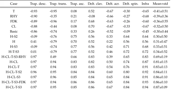
4.4 Resultant GH joint reaction force of the 16 combinations in %BW over the abduction angle of the humerus. Grey depicts the reference force data (Retrieved 15. May, 2018 from http://www.OrthoLoad.com, files: s1r_210206_1_42, s2r_040408_1_2, s2r_270306_1_86s3l_190308_1_48, s4r_140207_1_70, s5r_131108_1_40, s8r_161208_1_17, s8r_161208_1_31) and the continuous line the unchanged Basic model . . . . 64 4.5 Activity of considered muscle groups over the abduction angle. Con-
tinuous line: Mean EMG of all subjects. Grey area: standard deviation of EMG of all subjects. Dashed line: Mean activity of the Basic models of the considered muscle groups. Dash-dot line: Mean activity of the H-CL-T-S3 parameter combination. . . . . 66 5.1 Deltoid muscle elements of the model of the AMMR v.7.2 with an-
terior elements highlighted in red. Left: Abduction at 90◦ , Right:
Abduction at 120◦ . . . . 72 5.2 Model with the translated tori in default position at 0◦abduction (left)
and muscle pathing at 120◦ abduction, tori are graphically omitted (right) . . . . 74 5.3 Torus obstacles of the deltoid within the AMS. On the left is the model
in default position at 0◦ of abduction. On the right is the model at 120◦ abduction, where the position of the tori translate on the long axis of the humerus with a fixed distance to the acromion (blue coor- dinate system) as the humeral head moves under the scapula (green coordinate system) . . . . 75 5.4 Moment arms during glenohumeral abduction in the range 20−120◦
of the anterior deltoid elements. Grey: moment arms from a cadaver study by Ackland et al., 2008 Black: anterior deltoid moment arms of the via point model, 6 associated model elements. Lines are labelled from 1-6 from the most anterior to the most lateral element. Orange:
anterior deltoid moment arms of the ellipsoid model, 4 associated model elements. Lines are labelled from 1-4 from the most anterior to the most lateral element. Blue: anterior deltoid moment arms of the torus model, 4 associated model elements. Lines are labelled from 1-4 from the most anterior to the most lateral element. . . . 81
List of Figures
5.5 Moment arms during glenohumeral abduction in the range 20−120◦. Each part of the deltoid (anterior, lateral, posterior) is represented by 4 model elements (black lines), with an increasing numeration from 1- 12 from the most anterior to the most posterior element. Grey depicts the moment arms from a cadaver study (Ackland et al., 2008) . . . . 83 5.6 Activity of the anterior, lateral and posterior deltoid groups during
abduction between 30-120° of the EMG mean (blue) and it’s standard deviation (blue envelope), the mean of the NOFM model (purple), the FXZ model (yellow) and the ALLFM configuration (red) with p = 5 . 85 5.7 Resultant GH joint reaction force in %BW over the abduction an-
gle of the humerus. Grey depicts an envelope of the in-vivo data (Retrieved 15. May, 2018 from http://www.OrthoLoad.com, files:
s1r_210206_1_42, s2r_040408_1_2, s2r_270306_1_86, s3l_190308_1_48, s4r_140207_1_70, s5r_131108_1_40, s8r_161208_1_17, s8r_161208_1_31) in comparison to the NOFM (purple), FXZ (yellow) and ALLFM ap- proaches in force transmission . . . . 86 5.8 Forces transmitted from the anterior, lateral and posterior tori carrier
elements onto the humerus from the ALLFM model (see 5.2.3) dur- ing abduction of the humerus in the range 30-120°. X,Y and Z com- ponents are expressed in the humerus coordinate frame (Figure 5.3, green coordinate system). . . . 88 5.9 Resultant GH joint reaction force over abduction angle of single al-
terations of the Hill model. Single parameters are set to 50% of their initial value. Parameters are explained in detail in Table 5.1. Grey de-
picts the in-vivo force data (Retrieved 15. May, 2018 from www.OrthoLoad.com, files: s1r_210206_1_42, s2r_040408_1_2, s2r_270306_1_86, s3l_190308_1_48, s4r_140207_1_70, s5r_131108_1_40, s8r_161208_1_17, s8r_161208_1_31). 89 5.10 Resultant GH joint reaction force over abduction angle of single alter-
ations of the Hill model, single parameters set to 200% of their initial value. Parameters are explained in detail in Table 5.1. Grey depicts the in-vivo force data(Retrieved 15. May, 2018 from www.OrthoLoad.com, files: s1r_210206_1_42, s2r_040408_1_2, s2r_270306_1_86, s3l_190308_1_48, s4r_140207_1_70, s5r_131108_1_40, s8r_161208_1_17, s8r_161208_1_31). 90
List of Figures
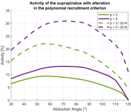
5.11 Activity of the m. supraspinatus muscle during humeral abduction in the range 30-120° of four model configurations: polynomial recruit- ment criterion with power p=3 (green) and p=5 (purple). Dashed lines are with a force applied to the palm of 20 N . . . . 91 5.12 Activity of the anterior, lateral and posterior deltoid groups during
abduction between 30-120° of the EMG mean (blue), the mean of the ALLFM model with p = 5 (purple) and the ellipsoid model with p = 5 (orange). Standard deviations are provided by the corresponding shaded areas . . . . 93 5.13 Resultant GH joint reaction force in %BW over the abduction angle of
the humerus. Grey depicts an envelope of the in-vivo data from lit- erature (Retrieved 15. May, 2018 from http://www.OrthoLoad.com, files: s1r_210206_1_42, s2r_040408_1_2, s2r_270306_1_86, s3l_190308_1_48, s4r_140207_1_70, s5r_131108_1_40, s8r_161208_1_17, s8r_161208_1_31) in comparison to the torus model with p=5 and the ellipsoid model with p=5 . . . . 94 6.1 Different origins of the biceps caput longum a) original model (ORG)
b) tendon insertion on the bicipital groove at the humeral head (HH) c) tendon insertion on the coracoid at the origin of the caput breve (CB)105 6.2 IS force in the GH joint over the EL flexion angle during flexion for
the ORG, HH, CB and OFF model . . . . 108 6.3 IS force in the GH joint over the EL pronation angle during pronation
for the ORG, HH, CB and OFF model . . . . 109 6.4 IS force in the GH joint over the EL pronation angle during the pour-
ing motion for the ORG, HH, CB and OFF model . . . . 110 6.5 Representation of the force direction acting on the glenoid, where the
arrows indicate the largest shift from the ORG model to the surgical models for flexion (magenta), pronation (green) and pouring (red) . . 111 6.6 PA force in the EL joint over the EL flexion angle during the flexion
motion for the ORG, HH, CB and OFF model . . . . 112 6.7 PA force in the EL joint over the EL pronation angle during the prona-
tion motion for the ORG, HH, CB and OFF model . . . . 113 6.8 PA force in the EL joint over the EL pronation angle during the pour-
ing motion for the ORG, HH, CB and OFF model . . . . 114
List of Figures
7.1 EMG sensor placement of the 14 contemplated muscles of interest on a healthy test subject. . . . 123 7.2 Scapula segment with the simulated glenoid (blue dots) and the coor-
dinate system in which the forces acting on the glenoid are expressed.
The Y direction of the coordinate system is referred to from inferior to superior, the Z anterior to posterior and the negative X direction as compression force. . . . 126 7.3 EMG computation steps of the middle deltoid of one subject dur-
ing neutral position (5 N) trial. Top: raw EMG signal (blue). Sec- ond: wavelet de-noised signal (cyan), RMS of the rloess smoothed wavelet signal (orange). Third: RMS interpolated over abduction an- gle from MoCap model (blue) and computed for 5° increments (red dot). Fourth: normalized signal (blue) and 5° increments (red dots) to the 85° position. . . . 128 7.4 Activities of the m. supraspinatus computed by the models of the
healthy control group over the abduction angle in 5° increments. Ac- tivities are from the neutral position, internal rotation and external rotation trials without weight. . . . 130 7.5 Activities of the m. supraspinatus computed by the models of the
healthy control group over the abduction angle in 5° increments. Ac- tivities are from the neutral position, internal rotation and external rotation trials with 5 N load in hand. . . . 131 7.6 Computed muscle activities of the anterior, posterior and lateral del-
toids over the abduction angle in 5° increments during the internal rotation trial with 5 N load in hand. Blue depicts the activities of the intact model and red the modelled tear of the m. supraspinatus Blue depicts the activities of the intact model and red the modelled tear of the m. supraspinatus of the healthy subject cohort. . . . . 133 7.7 Computed muscle activities of infraspinatus, subscapularis and teres
minor over the abduction angle in 5° increments during the internal rotation trial with 5 N load in hand. Blue depicts the activities of the intact model and red the modelled tear of the m. supraspinatus of the healthy subject cohort. . . . 134
List of Figures
7.8 Computed muscle activities of the biceps, triceps and pectoralis ma- jor over the abduction angle in 5° increments during the internal ro- tation trial with 5 N load in hand. Blue depicts the activities of the intact model and red the modelled tear of the m. supraspinatus of the healthy subject cohort. . . . 135 7.9 Projected median GH joint reaction force of all models onto the glenoid
of intact and pathological models of the healthy subject cohort dur- ing the internal rotation trial with 5 N load in hand. Intact/healthy models (blue) and pathological models (red) with their starting value at 25° abduction and the progression up to 85° abduction. . . . 137 7.10 Compression force, inferior-superior force and anterior-posterior force
of intact (blue) and pathological (red) models of the healthy subject cohort during the internal rotation trial with 5 N load in hand over the abduction angle in 5° increments. . . . 138 7.11 Flexion and external rotation angle over abduction of the heatly co-
hort (blue) and pathological cohort (red) during the internal rotation trial with 5 N load in hand. . . . 140 7.12 Computed muscle activities of the anterior, posterior and lateral del-
toids over the abduction angle in 5° increments during the internal rotation trial with 5 N load in hand. Blue depicts the activities of the intact model of the healthy subject group and red the modelled tear of the m. supraspinatus of the patient group. . . . 141 7.13 Computed muscle activities of the infraspinatus, subscapularis and
teres minor over the abduction angle in 5° increments during the in- ternal rotation trial with 5 N load in hand. Blue depicts the activities of the intact model of the healthy subject group and red the modelled tear of the m. supraspinatus of the patient group. . . . 142 7.14 Computed muscle activities of the biceps, triceps and pectoralis major
over the abduction angle in 5° increments during the internal rotation trial with 5 N load in hand. Blue depicts the activities of the intact model of the healthy subject group and red the modelled tear of the m. supraspinatus of the patient group. . . . 143
List of Figures
7.15 Projected median GH joint reaction force of all models onto the glenoid of intact models of the healthy subject cohort and pathological mod- els of the patient group during the internal rotation trial with 5 N load in hand. Intact models of the healthy control (blue) and patho- logical models of the patient group (red) with their starting value at 25° abduction and the progression up to 85° abduction. . . . 145 7.16 Compression force, inferior-superior force and anterior-posterior force
of intact models of the healthy control (blue) and pathological models of the patient group (red) during the internal rotation trial with 5 N load in hand over the abduction angle in 5° increments. . . . 146 7.17 EMG muscle activities normalized to the 85° position of the neutral
position trial with 5 N load in hand of the trapezius pars descendens, trapezius pars transversa and trapezius pars ascendens over the ab- duction angle in 5° increments during the internal rotation trial with 5 N load in hand. Blue depicts the EMG activities of the healthy subject group and red of the patient group. . . . 149 7.18 EMG muscle activities normalized to the 85° position of the neutral
position trial with 5 N load in hand of the anterior deltoid, lateral del- toid and posterior deltoid over the abduction angle in 5° increments during the internal rotation trial with 5 N load in hand. Blue depicts the EMG activities of the healthy subject group and red of the patient group. . . . 150 7.19 EMG muscle activities normalized to the 85° position of the neutral
position trial with 5 N load in hand of the infraspinatus, serratus ante- rior and latissimus over the abduction angle in 5° increments during the internal rotation trial with 5 N load in hand. Blue depicts the EMG activities of the healthy subject group and red of the patient group. . 151 7.20 EMG muscle activities normalized to the 85° position of the neutral
position trial with 5 N load in hand of the biceps, triceps and rhom- boideus minor over the abduction angle in 5° increments during the internal rotation trial with 5 N load in hand. Blue depicts the EMG activities of the healthy subject group and red of the patient group. . 152
List of Figures
7.21 EMG muscle activities normalized to the 85° position of the neutral position trial with 5 N load in hand of the rhomboideus major and pectoralis major over the abduction angle in 5° increments during the internal rotation trial with 5 N load in hand. Blue depicts the EMG activities of the healthy subject group and red of the patient group. . 153 A.1 Resultant GHJF in the range of 20−120◦ humeral abduction. The
grey shaded area is an envelope of the in-vivo data obtained by Bergmann et al. The orange line is the average calculated GHJF from the motion capture models with ellipsoid wrapping and p = 5, with the orange shaded area representing the standard deviation. . . . 177 A.2 Activity of the anterior, lateral and posterior deltoid groups during
abduction between 30-120° of the EMG mean (blue) and the ellipsoid model with p = 5 (orange). Standard deviations are provided by the corresponding shaded areas . . . . 178 A.3 Moment arms during glenohumeral abduction in the range 20−120◦
of the lateral deltoid elements. Grey: moment arms from a cadaver study by Ackland et al., 2008 Black: lateral deltoid moment arms of the via point model, 4 associated model elements. Orange: lateral deltoid moment arms of the ellipsoid model, 4 associated model ele- ments. Blue: lateral deltoid moment arms of the torus model, 4 asso- ciated model elements. . . . 179 A.4 Moment arms during glenohumeral abduction in the range 20−120◦
of the posterior deltoid elements. Grey: moment arms from a cadaver study by Ackland et al., 2008 Black: posterior deltoid moment arms of the via point model, 2 associated model elements. Orange: poste- rior deltoid moment arms of the ellipsoid model, 4 associated model elements. Blue: posterior deltoid moment arms of the torus model, 4 associated model elements. . . . 180 A.5 Moments transmitted from the anterior, lateral and posterior tori car-
rier elements onto the humerus from the ALLFM model (see 5.2.3) during abduction of the humerus in the range 30-120°. X,Y and Z components are expressed in the humerus coordinate frame (Figure 5.3, green coordinate system). . . . 181
List of Figures
A.6 Activity of the anterior, lateral and posterior deltoid groups during abduction between 30-120° of the EMG mean (blue), the ellipsoid (or- ange) and the torus model (purple) with p = 3. . . . 183 A.7 Resultant GH joint reaction force in %BW over the abduction an-
gle of the humerus. Grey depicts an envelope of the in-vivo data (Retrieved 15. May, 2018 from http://www.OrthoLoad.com, files:
s1r_210206_1_42, s2r_040408_1_2, s2r_270306_1_86, s3l_190308_1_48, s4r_140207_1_70, s5r_131108_1_40, s8r_161208_1_17, s8r_161208_1_31) in comparison to the the ellipsoid (orange) and the torus model (pur- ple) with p = 3. . . . 184 B.1 Forces and moments acting on the EL joint over the EL flexion angle
during flexion for the ORG, HH, CB and OFF model . . . . 186 B.2 Forces and moments acting on the EL joint over the EL pronation
angle during pronation for the ORG, HH, CB and OFF model . . . . 187 B.3 Forces and moments acting on the EL joint over the EL pronation
angle during the pouring motion for the ORG, HH, CB and OFF model 188 B.4 Forces in the GH joint over the EL flexion angle during flexion for the
ORG, HH, CB and OFF model . . . . 190 B.5 Forces in the GH joint over the EL pronation angle during pronation
for the ORG, HH, CB and OFF model . . . . 191 B.6 Forces in the GH joint over the EL pronation angle during the pouring
motion for the ORG, HH, CB and OFF model . . . . 192 C.1 Computed muscle activities of the anterior, posterior and lateral del-
toids over the abduction angle in 5° increments during the neutral position trial. Blue depicts the activities of the intact model and red the modelled tear of the m. supraspinatus. Blue depicts the activities of the intact model and red the modelled tear of the m. supraspinatus of the healthy subject cohort. . . . 194 C.2 Computed muscle activities of infraspinatus, subscapularis and teres
minor over the abduction angle in 5° increments during the neutral position trial with 5 N load in hand. Blue depicts the activities of the intact model and red the modelled tear of the m. supraspinatus of the
List of Figures
C.3 Computed muscle activities of the biceps, triceps and pectoralis major over the abduction angle in 5° increments during the neutral position trial. Blue depicts the activities of the intact model and red the mod- elled tear of the m. supraspinatus of the healthy subject cohort. . . . 196 C.4 Computed muscle activities of the anterior, posterior and lateral del-
toids over the abduction angle in 5° increments during the neutral position trial with 5 N load in hand. Blue depicts the activities of the intact model and red the modelled tear of the m. supraspinatus. Blue depicts the activities of the intact model and red the modelled tear of the m. supraspinatus of the healthy subject cohort. . . . . 197 C.5 Computed muscle activities of infraspinatus, subscapularis and teres
minor over the abduction angle in 5° increments during the neutral position trial with 5 N load in hand. Blue depicts the activities of the intact model and red the modelled tear of the m. supraspinatus of the healthy subject cohort. . . . 198 C.6 Computed muscle activities of the biceps, triceps and pectoralis ma-
jor over the abduction angle in 5° increments during the neutral po- sition trial with 5 N load in hand. Blue depicts the activities of the intact model and red the modelled tear of the m. supraspinatus of the healthy subject cohort. . . . 199 C.7 Computed muscle activities of the anterior, posterior and lateral del-
toids over the abduction angle in 5° increments during the internal rotation trial. Blue depicts the activities of the intact model and red the modelled tear of the m. supraspinatus. Blue depicts the activities of the intact model and red the modelled tear of the m. supraspinatus of the healthy subject cohort. . . . 200 C.8 Computed muscle activities of infraspinatus, subscapularis and teres
minor over the abduction angle in 5° increments during the internal rotation trial. Blue depicts the activities of the intact model and red the modelled tear of the m. supraspinatus of the healthy subject co- hort. . . . . 201 C.9 Computed muscle activities of the biceps, triceps and pectoralis ma-
jor over the abduction angle in 5° increments during the internal ro- tation trial. Blue depicts the activities of the intact model and red the modelled tear of the m. supraspinatus of the healthy subject cohort. 202
List of Figures
C.10 Computed muscle activities of the anterior, posterior and lateral del- toids over the abduction angle in 5° increments during the external rotation trial. Blue depicts the activities of the intact model and red the modelled tear of the m. supraspinatus. Blue depicts the activities of the intact model and red the modelled tear of the m. supraspinatus of the healthy subject cohort. . . . 203 C.11 Computed muscle activities of infraspinatus, subscapularis and teres
minor over the abduction angle in 5° increments during the external rotation trial. Blue depicts the activities of the intact model and red the modelled tear of the m. supraspinatus of the healthy subject co- hort. . . . . 204 C.12 Computed muscle activities of the biceps, triceps and pectoralis ma-
jor over the abduction angle in 5° increments during the external ro- tation trial. Blue depicts the activities of the intact model and red the modelled tear of the m. supraspinatus of the healthy subject cohort. 205 C.13 Computed muscle activities of the anterior, posterior and lateral del-
toids over the abduction angle in 5° increments during the external rotation trial with 5 N load in hand. Blue depicts the activities of the intact model and red the modelled tear of the m. supraspinatus. Blue depicts the activities of the intact model and red the modelled tear of the m. supraspinatus of the healthy subject cohort. . . . . 206 C.14 Computed muscle activities of infraspinatus, subscapularis and teres
minor over the abduction angle in 5° increments during the external rotation trial with 5 N load in hand. Blue depicts the activities of the intact model and red the modelled tear of the m. supraspinatus of the healthy subject cohort. . . . 207 C.15 Computed muscle activities of the biceps, triceps and pectoralis ma-
jor over the abduction angle in 5° increments during the external ro- tation trial with 5 N load in hand. Blue depicts the activities of the intact model and red the modelled tear of the m. supraspinatus of the healthy subject cohort. . . . 208 C.16 Compression force, inferior-superior force and anterior-posterior force
of intact (blue) and pathological (red) models of the healthy subject
List of Figures
C.17 Projected median GH joint reaction force of all models onto the glenoid of intact and pathological models of the healthy subject cohort during the neutral position trial. Intact/healthy models (blue) and patholog- ical models (red) with their starting value at 25° abduction and the progression up to 85° abduction. . . . 211 C.18 Compression force, inferior-superior force and anterior-posterior force
of intact (blue) and pathological (red) models of the healthy subject cohort during the neutral position trial with 5 N load in hand over the abduction angle in 5° increments. . . . 212 C.19 Projected median GH joint reaction force of all models onto the glenoid
of intact and pathological models of the healthy subject cohort dur- ing the neutral position trial with 5 N load in hand. Intact/healthy models (blue) and pathological models (red) with their starting value at 25° abduction and the progression up to 85° abduction. . . . 213 C.20 Compression force, inferior-superior force and anterior-posterior force
of intact (blue) and pathological (red) models of the healthy subject cohort during the internal rotation trial over the abduction angle in 5° increments. . . . 214 C.21 Projected median GH joint reaction force of all models onto the glenoid
of intact and pathological models of the healthy subject cohort during the internal rotation trial. Intact/healthy models (blue) and patholog- ical models (red) with their starting value at 25° abduction and the progression up to 85° abduction. . . . 215 C.22 Compression force, inferior-superior force and anterior-posterior force
of intact (blue) and pathological (red) models of the healthy subject cohort during the external rotation trial over the abduction angle in 5° increments. . . . 216 C.23 Projected median GH joint reaction force of all models onto the glenoid
of intact and pathological models of the healthy subject cohort during the external rotation trial. Intact/healthy models (blue) and patho- logical models (red) with their starting value at 25° abduction and the progression up to 85° abduction. . . . 217
List of Figures
C.24 Compression force, inferior-superior force and anterior-posterior force of intact (blue) and pathological (red) models of the healthy subject cohort during the external rotation trial with 5 N load in hand over the abduction angle in 5° increments. . . . 218 C.25 Projected median GH joint reaction force of all models onto the glenoid
of intact and pathological models of the healthy subject cohort dur- ing the external rotation trial with 5 N in hand. Intact/healthy models (blue) and pathological models (red) with their starting value at 25°
abduction and the progression up to 85° abduction. . . . 219 C.26 Flexion and external rotation angle over abduction of the heathy co-
hort (blue) and pathological cohort (red) during the neutral position trial. . . . 225 C.27 Flexion and external rotation angle over abduction of the heathy co-
hort (blue) and pathological cohort (red) during the neutral position trial with 5 N load in hand. . . . 226 C.28 Flexion and external rotation angle over abduction of the heathy co-
hort (blue) and pathological cohort (red) during the internal rotation trial. . . . 227 C.29 Flexion and external rotation angle over abduction of the heathy co-
hort (blue) and pathological cohort (red) during the external rotation trial. . . . 228 C.30 Flexion and external rotation angle over abduction of the heathy co-
hort (blue) and pathological cohort (red) during the external rotation trial with 5 N load in hand. . . . 229 C.31 Computed muscle activities of the anterior, posterior and lateral del-
toids over the abduction angle in 5° increments during the neutral position trial. Blue depicts the activities of the intact model of the healthy subject group and red the modelled tear of the m. supraspina- tus of the patient group. . . . 231 C.32 Computed muscle activities of the infraspinatus, subscapularis and
teres minor over the abduction angle in 5° increments during the neu- tral position trial. Blue depicts the activities of the intact model of the healthy subject group and red the modelled tear of the m. supraspina-
List of Figures
C.33 Computed muscle activities of the biceps, triceps and pectoralis major over the abduction angle in 5° increments during the neutral position trial. Blue depicts the activities of the intact model of the healthy subject group and red the modelled tear of the m. supraspinatus of the patient group. . . . 233 C.34 Computed muscle activities of the anterior, posterior and lateral del-
toids over the abduction angle in 5° increments during the neutral position trial with 5 N load in hand. Blue depicts the activities of the intact model of the healthy subject group and red the modelled tear of the m. supraspinatus of the patient group. . . . 234 C.35 Computed muscle activities of the infraspinatus, subscapularis and
teres minor over the abduction angle in 5° increments during the neu- tral position trial with 5 N load in hand. Blue depicts the activities of the intact model of the healthy subject group and red the modelled tear of the m. supraspinatus of the patient group. . . . 235 C.36 Computed muscle activities of the biceps, triceps and pectoralis major
over the abduction angle in 5° increments during the neutral position trial with 5 N load in hand. Blue depicts the activities of the intact model of the healthy subject group and red the modelled tear of the m. supraspinatus of the patient group. . . . 236 C.37 Computed muscle activities of the anterior, posterior and lateral del-
toids over the abduction angle in 5° increments during the internal rotation trial. Blue depicts the activities of the intact model of the healthy subject group and red the modelled tear of the m. supraspina- tus of the patient group. . . . 237 C.38 Computed muscle activities of the infraspinatus, subscapularis and
teres minor over the abduction angle in 5° increments during the in- ternal rotation trial. Blue depicts the activities of the intact model of the healthy subject group and red the modelled tear of the m.
supraspinatus of the patient group. . . . 238 C.39 Computed muscle activities of the biceps, triceps and pectoralis major
over the abduction angle in 5° increments during the internal rotation trial. Blue depicts the activities of the intact model of the healthy subject group and red the modelled tear of the m. supraspinatus of the patient group. . . . 239
List of Figures
C.40 Computed muscle activities of the anterior, posterior and lateral del- toids over the abduction angle in 5° increments during the external rotation trial. Blue depicts the activities of the intact model of the healthy subject group and red the modelled tear of the m. supraspina- tus of the patient group. . . . 240 C.41 Computed muscle activities of the infraspinatus, subscapularis and
teres minor over the abduction angle in 5° increments during the ex- ternal rotation trial. Blue depicts the activities of the intact model of the healthy subject group and red the modelled tear of the m.
supraspinatus of the patient group. . . . 241 C.42 Computed muscle activities of the biceps, triceps and pectoralis major
over the abduction angle in 5° increments during the external rotation trial. Blue depicts the activities of the intact model of the healthy subject group and red the modelled tear of the m. supraspinatus of the patient group. . . . 242 C.43 Computed muscle activities of the anterior, posterior and lateral del-
toids over the abduction angle in 5° increments during the external rotation trial with 5 N load in hand. Blue depicts the activities of the intact model of the healthy subject group and red the modelled tear of the m. supraspinatus of the patient group. . . . 243 C.44 Computed muscle activities of the infraspinatus, subscapularis and
teres minor over the abduction angle in 5° increments during the ex- ternal rotation trial with 5 N load in hand. Blue depicts the activities of the intact model of the healthy subject group and red the modelled tear of the m. supraspinatus of the patient group. . . . 244 C.45 Computed muscle activities of the biceps, triceps and pectoralis major
over the abduction angle in 5° increments during the external rotation trial with 5 N load in hand. Blue depicts the activities of the intact model of the healthy subject group and red the modelled tear of the m. supraspinatus of the patient group. . . . 245 C.46 Compression force, inferior-superior force and anterior-posterior force
of intact models of the healthy control (blue) and pathological mod- els of the patient group (red) during the neutral position trial over the
List of Figures
C.47 Projected median GH joint reaction force of all models onto the glenoid of intact models of the healthy subject cohort and pathological models of the patient group during the neutral position trial. Intact models of the healthy control (blue) and pathological models of the patient group (red) with their starting value at 25° abduction and the pro- gression up to 85° abduction. . . . 248 C.48 Compression force, inferior-superior force and anterior-posterior force
of intact models of the healthy control (blue) and pathological models of the patient group (red) during the neutral position trial with 5 N load in hand over the abduction angle in 5° increments. . . . 249 C.49 Projected median GH joint reaction force of all models onto the glenoid
of intact models of the healthy subject cohort and pathological mod- els of the patient group during the neutral position trial with 5 N load in hand. Intact models of the healthy control (blue) and pathological models of the patient group (red) with their starting value at 25° ab- duction and the progression up to 85° abduction. . . . 250 C.50 Compression force, inferior-superior force and anterior-posterior force
of intact models of the healthy control (blue) and pathological mod- els of the patient group (red) during the internal rotation trial over the abduction angle in 5° increments. . . . 251 C.51 Projected median GH joint reaction force of all models onto the glenoid
of intact models of the healthy subject cohort and pathological models of the patient group during the internal rotation trial. Intact models of the healthy control (blue) and pathological models of the patient group (red) with their starting value at 25° abduction and the pro- gression up to 85° abduction. . . . 252 C.52 Compression force, inferior-superior force and anterior-posterior force
of intact models of the healthy control (blue) and pathological models of the patient group (red) during the external rotation trial over the abduction angle in 5° increments. . . . 253
List of Figures
C.53 Projected median GH joint reaction force of all models onto the glenoid of intact models of the healthy subject cohort and pathological models of the patient group during the external rotation trial. Intact models of the healthy control (blue) and pathological models of the patient group (red) with their starting value at 25° abduction and the pro- gression up to 85° abduction. . . . 254 C.54 Compression force, inferior-superior force and anterior-posterior force
of intact models of the healthy control (blue) and pathological models of the patient group (red) during the external rotation trial with 5 N load in hand over the abduction angle in 5° increments. . . . 255 C.55 Projected median GH joint reaction force of all models onto the glenoid
of intact models of the healthy subject cohort and pathological mod- els of the patient group during the external rotation trial with 5 N load in hand. Intact models of the healthy control (blue) and patho- logical models of the patient group (red) with their starting value at 25° abduction and the progression up to 85° abduction. . . . 256 C.56 EMG muscle activities normalized to the 85° position of the neutral
position trial with 5 N load in hand of the trapezius pars descendens, trapezius pars transversa and trapezius pars ascendens over the ab- duction angle in 5° increments during the neutral position trial. Blue depicts the EMG activities of the healthy subject group and red of the patient group. . . . 263 C.57 EMG muscle activities normalized to the 85° position of the neutral
position trial with 5 N load in hand of the anterior deltoid, lateral del- toid and posterior deltoid over the abduction angle in 5° increments during the neutral position trial. Blue depicts the EMG activities of the healthy subject group and red of the patient group. . . . 264 C.58 EMG muscle activities normalized to the 85° position of the neutral
position trial with 5 N load in hand of the infraspinatus, serratus an- terior and latissimus over the abduction angle in 5° increments dur- ing the neutral position trial. Blue depicts the EMG activities of the healthy subject group and red of the patient group. . . . 265