Waste Incineration
CO
2Capture and Re-Use at a Waste Incinerator
Patrick Huttenhuis, Andy Roeloffzen and Geert Versteeg
1. Validation of the new SBC injection technology ...308
2. Process design ...309
3. Fundamentals of the SBC process ...311
4. Conclusion ...314
5. Nomenclature ...315
6. References ...315 Recently a new innovative process developed by Procede Gas Treating B.V. has been commissioned at line 3 of the Twence plant, a Waste-To-Energy (WTE) plant located in the eastern part of the Netherlands. In this process the CO2, that usually is emitted to atmosphere, is in this new application, scrubbed from the flue gas and the obtained pure CO2 stream is used to produce a sodium bicarbonate slurry (SBC). Instead of the conventional SBC flue gas scrubbing process, where dry SBC particles are used, this SBC slurry will be injected to remove the acid components from the flue gas, before the gas is emitted to atmosphere. Due to the implementation of this process the carbon footprint of the Twence installation is reduced. The new SBC plant produces 8,000 tons of sodium bicarbonate annually and to produce this amount of SBC 2,000 ton per year CO2 is captured from the flue gas. The CO2 originates for about 50 percent from biomass.
In this new process the captured CO2 is used for mineralization and is converted in an innovative new reactor configuration from sodium carbonate to sodium bicarbonate (SBC). So instead of purchasing the expensive product sodium bicarbonate by Twence, the cheaper product sodium carbonate will be used as raw material in the new process.
Another advantage of the new technology is, that 1 ton carbonate will be converted to 1.6 ton bicarbonate. This will result in additional cost savings due to lower transporta- tion costs and related additional CO2 emissions. The third and possible most important advantage of this process is the negative carbon footprint. At the moment NaHCO3 is mainly produced from Na2CO3 and CO2, where the CO2 is obtained by burning fossil fuels. In this new process the Na2CO3 is produced from green CO2 produced at the waste incinerator.
The sodium bicarbonate is used in the incinerator to remove impurities – acidic components – before the flue gas is emitted to atmosphere. The project was started on the 1st of July 2011 with the initial development of the new technology. The main objectives of the project were:
Waste Incineration
• Demonstration of an unique carbon dioxide capture technology leading to lower investment costs, lower consumption of absorption liquids, as well as lower opera- tional costs;
• Demonstration of the re-use of the captured carbon dioxide for the on-site pro- duction of sodium bicarbonate to be used in the flue gasses cleaning system of the WTE plant;
• Evaluation of the concept of on-site production, storage and re-use of carbon dioxide;
• Review of the financial-economic perspective of the new technology.
End of 2014 the plant was commissioned at the Twence location in Hengelo, the Netherlands.
1. Validation of the new SBC injection technology
Before this project was implemented Twence used solid sodium bicarbonate particles and this solid material was sprayed in the flue gas channel. In the new technology a 40 wt.-%
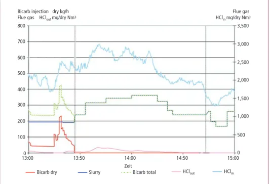
bicarbonate slurry is produced and instead of SBC particles, this slurry is injected to re- move the acidic impurities from the flue gas. The efficiency of this new spray technology with SBC slurry was tested at full scale – upto 1 ton/h slurry injection rate – at a Waste Power Plant in Bremen, Germany (BREWA). In Figure 1 a summary of the test results are presented graphically. Initially the tests were started with the injection of dry SBC and slurry SBC, however, after some time the injection of dry SBC was stopped completely.
13:000
Bicarb dry Slurry Bicarb total HClout HClin
13:50 14:00
Zeit
14:50 15:000
500 1,000 1,500 2,000 2,500 3,000 3,500
100 200 300 400 500 600 700 800
Bicarb injection dry kg/h
Flue gas HClout mg/dry Nm3 Flue gas
HClin mg/dry Nm3
Figure 1: Test results of SBC slurry injection at BREWA
Waste Incineration
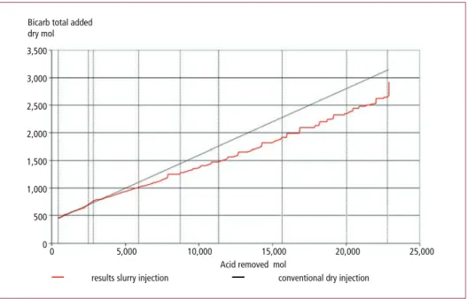
From Figure 1 can be concluded that also with the injection of SBC slurry, a high removal rate of acid components was achieved. In Figure 2 the amount of injected NaHCO3 is presented as function of amount removed acid gas.
00 5,000
results slurry injection
10,000 15,000 20,000 25,000
500 1,000 1,500 2,000 2,500 3,000 3,500
Bicarb total added dry mol
conventional dry injection Acid removed mol
Figure 2: Test results of SBC slurry injection at BREWA compared with dry injection performance;
total amount NaHCO3 as function of total amount removed acid gas
From Figure 2 can be concluded that the efficiency of the SBC slurry (red line) is com- parable and even slightly better than the efficiency of the conventional SBC injection technology (black line). Based on these tests results a design of a full size CO2 capture plant and SBC production plant was prepared for the Line 3 at Twence. To develop this process from idea to commercial installation a strong consortium was formed between three companies:
• Procede was responsible for the R&D activities and developed the Conceptual and Basic Design of the plant;
• Bouman Process Technology was responsible for the Detailed Design, Equipment Selection and Supply, and the Construction Phase;
• Twence was responsible for the overall Project Management, Plant Integration and Commissioning Phase.
2. Process design
Starting point of the project was to design and built a full scale SBC production plant to pu- rify the total flue gas stream of line 3 at Twence. Therefore 2,000 ton/year CO2 (= 250 kg/h) should be captured with a suitable CO2 capture process and with this captured CO2
Waste Incineration
8,000 ton/year SBC will be produced. The SBC slurry will be produced from a satu- rated sodium carbonate solution resulting in a 40 wt.-% SBC slurry. This high SBC concentration is required to minimize the temperature drop of the flue gas due to the slurry injection. The SBC production unit is designed to obtain a high conversion (> 90 percent) of carbonate to bicarbonate at almost 100 percent conversion of CO2. The production of CO2 does take place according the following reaction equation:
Na2CO3 + H2O + CO2 → 2 NaHCO3
Na2CO3 (30 wt.-% solution) + CO2 (pure gas) → NaHCO3 (40 wt.-% slurry =
± 35 wt.-% solids).
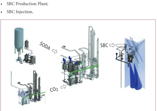
The following process steps can be identified to produce the sodium bicarbonate from sodium carbonate:
• Soda Dissolve Unit;
• Quench and CO2 Capture Plant;
• SBC Production Plant;
• SBC Injection.
SOD A SBC
CO2
Figure 3: Schematic overview of the SBC process installed at Twence
A side stream of the flue gas of Line 3 is routed to a Quench. In this unit the flue gas is cooled and acidic impurities, which are still present in the flue gas in low concent- rations, are removed. The pH of the quench liquid is kept constant by adding a small amount of concentrated sodium carbonate solution from the soda production unit.
In the Soda Dissolve Unit solid soda is dissolved in water and this solution is routed to the bicarbonate production unit. The cleaned and cooled flue gas is routed to the
Waste Incineration
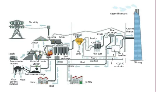
CO2 capture installation and in this installation pure CO2 is produced with the solvent Bilisol. This is a biodegradable solvent developed by Procede with a low degradation rate and very low volatility. The pure CO2 is routed to two stirred tank reactors, which are connected in series. In two steps the sodium carbonate solution is converted with the CO2 gas to a sodium bicarbonate slurry. This SBC slurry is buffered and pumped via a SBC circulation pipeline to two injection nozzles, where the slurry is injected in the flue gas channel together with steam. For the CO2 capture, SBC production and SBC injection process several utilities – steam, heat and cooling – are used from existing facilities at the Twence plant Figure 4.
Electricity
Gripper
Cleaned flue gases
exchangerHeat DeNox
Cloth filter
Filter dust ashesFly
Reactor Turbine Electrical
filter
Chimney Slurry
injection
CO2/sBC Installation Steam
Factory Heat Heat
Heat Houses
oven and boiler
Bottom-ashes storage Household waste Supply
Clean building materials
Metal
Cleaned flue gas Generator
Gripper
exchangerHeat Raw materials
recovery
Slurry injection
Figure 4: Schematic overview of the Twence waste to energy plant (line 3)
3. Fundamentals of the SBC process
The gas treating part of the process (Quench and CO2 capture plant) have been designed with the Procede Process Simulator. This is a rate based simulator specific developed for the development of gas treating processes [4]. All relevant properties of the Bilisol solvent have been measured and incorporated in the process simulator. The CO2 capture plant built at Twence is a smaller version of the Bilisol CO2 capture plant operating in Delta (British Colombia) and also designed by Procede Gas Treating B.V. At this plant in Delta the CO2 is captured from a flue gas stream coming from a wood burner and the CO2 is directly used as fertilizer to growing fruits and vegetable.
The pure CO2 stream from the desorber is routed to two NBC reactors were the fol- lowing overall reaction takes place:
CO2 + CO32- + H2O → 2 HCO3– (1)
Waste Incineration
The overall reaction rate is determined by the CO2 concentration – i.e. partial pressure – and OH- concentration (i.e. pH). The reaction rate of reaction 1 has been determined in literature. The reaction rate constant as determined by Pinsent et al [3] has been used to design the bicarbonate reactors. The absorption rate of CO2 in soda has been determined experimentally in a lab scale stirred reactor and from these experiments it appeared that the experimentally determined absorption rate was 30 to 40 percent higher than the absorption rate determined with the correlation of Pinsent [3], espe- cially in the high CO2 loading range (high conversion). Most likely explanation for this behavior is that CO2 can also react directly to bicarbonate with carbonate in a similar mechanism as tertiary amines do react with CO2 [5]. However, to develop a reliable, robust design, it was assumed that the absorption rate is determined by the reaction rate of CO2 and OH- as is assumed in literature usually.
To determine the reaction regime, first the Hatta number was calculated. In this di- mensionless parameter, the rate of reaction in the liquid film is compared to the rate of diffusion through this film. The Hatta number can be calculated as follows:
Ha = k1,1COH-DCO2
kL (2)
From this calculation it was estimated that the Hatta number was significant lower than 1 for chemical reaction 1. This means that the reaction rate is slow compared to the mass transfer. For this specific case the Hinterland ratio (Al) should be calculated, to determine the CO2 concentration in the liquid bulk. The Hinterland ratio is defined as the ratio between the total reaction phase volume and the volume of the mass transfer film and can be estimated from the following correlation [6]:
Al = sLkL
aDCO2 (3)
From the value of the Hinterland ratio it could be concluded that the concentration CO2 in the liquid bulk was negligible, i.e. the reaction does take place mainly in the gas-liquid film. In this case the absorption rate of CO2 in the reactor could be calculated with the following formula – no chemical enhancement:
-rCO2 = mCO2kLaCCO2,G (4)
The physical solubility of CO2 in the liquid (mCO2) was derived from literature data and CCO2,G is determined by the CO2 partial pressure in the reactors. The liquid side mass transfer coefficient (kL) and gas-liquid interfacial area (a) are mainly determined by the reactor configuration and physical properties of the liquid phase.
Several reactor concepts have been evaluated and the two in series stirred reactor concept has been selected, due to high mass transfer rates, flexibility and robust design. In this reactor configuration two in series located stirred tank reactors are used. In literature several correlations are available to design stirred tank reactors.
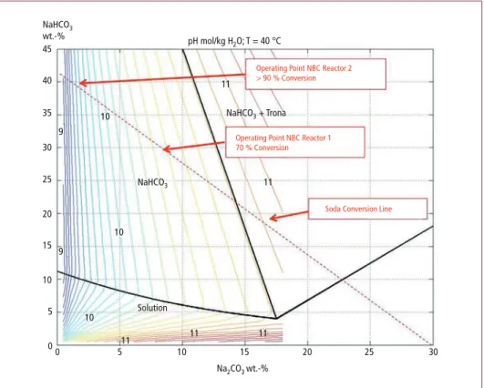
The first reactor is designed for approximately 70 percent carbonate conversion, while the remaining conversion to bicarbonate is carried out in the second stirred reactor.
Waste Incineration
Pure CO2 is added to the reactors, no inert gas is available to produce interfacial area.
For this reason the CO2 is circulated over the reactor and part of the CO2 is added into the slurry via a gas inducing impeller.
The 70 percent conversion in the first reactor was based on the following two consi- derations:
• At conversions below 50 percent undesired trona (Na2CO3•NaHCO3•2H2O) [1]
may be formed and for this reason the conversion in the reactor should be signifi- cant higher to prevent the formation of this product (refer to Figure 4 for the phase envelope of sodium carbonate-bicarbonate);
• At 70 percent conversion the amount of particles is estimated at approximately 12 Vol.-% and above this solid concentration a steep decrease in mass transfer is observed in literature, i.e. [2]. At these conditions the mass transfer is difficult to predict and available correlations are less reliable.
00 5 10
11 11 11
11 11 10
10 10 9
9
15 Na2CO3 wt.-%
NaHCO3
NaHCO3 + Trona pH mol/kg H2O; T = 40 °C
Operating Point NBC Reactor 2
> 90 % Conversion
Operating Point NBC Reactor 1 70 % Conversion
Soda Conversion Line
Solution NaHCO3
wt.-%
20 25 30
5 10 15 20 25 30 40 45
35
Figure 5: Phase envelope of the sodiumcarbonate-bicarbonate system
So at 70 percent conversion a relatively small reactor volume is required to produce the bicarbonate. However, at high conversions, the solid concentration increases to approximately 20 Vol.-% and at this solid concentration, the mass transfer is reduced significantly compared to the mass transfer in case no solids present in the liquid phase.
Waste Incineration
So based on these assumptions and suitable mass transfer correlations from literature, the two SBC reactors have been designed.
In Figure 6 a picture of the total process CO2 capture plant and SBC reactor system is presented.
At the moment the commissioning phase of the project is finished and the preparations have been started to go to continues operation. During this commissioning phase it was concluded that both the CO2 capture plant and NBC production reactors were working according expectations. Full continues operation has been accomplished for several days and the conversion from carbonate to bicarbonate is almost 100 percent.
Slurry injection in the flue gas has been tested and was also successful.
During the commissioning phase some issues were encountered with the seals of the CO2 compressor and also the formation of slurry in the head space encountered some unexpected problems, however, these have been solved now.
When the complete testing phase of the process has been finished, the plant will be handed over to the operation team of Twence for full continuously operation.
Figure 6:
Overview of the SBC process installed at Twence
4. Conclusion
In this paper the development of a new process, which is the first in the world, has been described. The process is successfully developed from idea and lab scale tests to a full scale commercial process and has reduced the carbon footprint of the Twence plant. The market for this process looks very promising. Twence is one of the 11 WTE plants located in the Netherlands. At a European scale at the moment circa 450 WTE plants are in operation. Nowadays, these plants heavily invest in sophisticated filtering devices to minimize the emissions to the atmosphere. Sodium bicarbonate has shown
Waste Incineration
to be a very effective and efficient chemical for flue gas cleaning compared to other processes and an increasing amount of WTE plants recently switched to using this product or are considering switching. The installation described in this paper, which is unique in the world, may become an improved second generation bicarbonate flue gas cleaning process.
Acknowledgements This project is co-funded by the European Union within the CIP Eco-innovation initiative of the Competiveness and Innovation Framework Programme CIP and the provincie Overijssel.
5. Nomenclature
a interfacial gas-liquid area [m2•m-3] Al Hinterland ratio [-]
CCO2 CO2 concentration in the liquid phase [mol•m-3] DA diffusion coefficient of component A [m2•s-1] Ha Hatta number [-]
kL liquid side mass transfer coefficient [m•s-1] k1,1 the reaction rate constant [mol•m-3•s-1] mCO2 physical solubility of CO2 in the solvent [-]
rCO2 CO2 reaction rate [mol•m-2•s-1] εL liquid hold-up [-]
6. References
[1] Fosbol, P.L.; Thomsen, K.; Stenby, H.: Modeling of the Mixed Solvent Electrolyte System CO2- Na2CO3-NaHCO3-Monoethylene Glycol-Water. Ind. Eng. Chem. Res. 2009; 48: 4565-4578 [2] Lee, J.H.; Foster, N.R.: Measurement of Gas-Liquid Mass Transfer in Multi-Phase Reactors.
Applied. Catalysis. 1990; 63: 1-36
[3] Pinsent, B.; Pearson, L.; Roughton, F.: The kinetics of combination of carbon dioxide with hydroxide ions. Trans. Faraday Soc. 1956; 52: 1512-1520
[4] van Elk, E.P.; Arendsen, A.R.J.; Versteeg, G.F.: A new flowsheeting tool for flue gas treating.
Energy Procedia 2009; 1: 1481–1488
[5] Versteeg, G.F.; van Dijck, L.A.J.; van Swaaij, W.P.M.: On the Kinetics between CO2 and alkano- lamines both in aqueous and non-aqueous solutions: on overview. Chem. Eng. Comm. 1996;
144: 113-158
[6] Westerterp, K.R.; van Swaaij, W.P.W.; Beenackers, A.A.C.M.: Chemical Reactor Design and Ope- ration. Amsterdam: John Wiley & Sons, 1984, p. 386
Inserat
TBF
Bibliografische Information der Deutschen Nationalbibliothek Die Deutsche Nationalbibliothek verzeichnet diese Publikation in der Deutschen Nationalbibliografie; detaillierte bibliografische Daten sind im Internet über http://dnb.dnb.de abrufbar
Thomé-Kozmiensky, K. J.; Thiel, S. (Eds.): Waste Management, Volume 6 – Waste-to-Energy –
ISBN 978-3-944310-29-9 TK Verlag Karl Thomé-Kozmiensky
Copyright: Professor Dr.-Ing. habil. Dr. h. c. Karl J. Thomé-Kozmiensky All rights reserved
Publisher: TK Verlag Karl Thomé-Kozmiensky • Neuruppin 2016
Editorial office: Professor Dr.-Ing. habil. Dr. h. c. Karl J. Thomé-Kozmiensky,
Dr.-Ing. Stephanie Thiel, M. Sc. Elisabeth Thomé-Kozmiensky, Janin Burbott-Seidel und Claudia Naumann-Deppe
Layout: Sandra Peters, Anne Kuhlo, Janin Burbott-Seidel, Claudia Naumann-Deppe, Ginette Teske, Gabi Spiegel und Cordula Müller
Printing: Universal Medien GmbH, Munich
This work is protected by copyright. The rights founded by this, particularly those of translation, reprinting, lecturing, extraction of illustrations and tables, broadcasting, micro- filming or reproduction by other means and storing in a retrieval system, remain reserved, even for exploitation only of excerpts. Reproduction of this work or of part of this work, also in individual cases, is only permissible within the limits of the legal provisions of the copyright law of the Federal Republic of Germany from 9 September 1965 in the currently valid revision. There is a fundamental duty to pay for this. Infringements are subject to the penal provisions of the copyright law.
The repeating of commonly used names, trade names, goods descriptions etc. in this work does not permit, even without specific mention, the assumption that such names are to be considered free under the terms of the law concerning goods descriptions and trade mark protection and can thus be used by anyone.
Should reference be made in this work, directly or indirectly, to laws, regulations or guide- lines, e.g. DIN, VDI, VDE, VGB, or these are quoted from, then the publisher cannot ac- cept any guarantee for correctness, completeness or currency. It is recommended to refer to the complete regulations or guidelines in their currently valid versions if required for ones own work.