System-level Modeling and Design with the SpecC Language
Dissertation
zur Erlangung des Grades eines
Doktors der Naturwissenschaften
der Universitat Dortmund am Fachbereich Informatik
Rainer Domer von
Dortmund
2000
Dekan/Dekanin:
Gutachter:
System-level Modeling and Design with the SpecC Language
Dissertation
for the degree of
\Doktor der Naturwissenschaften"
submitted to the
Department of Computer Science at University of Dortmund
Rainer Domer by
Dortmund, Germany
2000
iii
For Julia
Abstract
The semiconductor roadmap estimates the design complexity for digital systems to continue to increase according to Moore's law. In the next years, embedded systems with 10ths of millions of transistors on one chip will be standard technology.
System-on-Chip (SOC) designs will integrate processor cores, memories and special- purpose custom logic into a complete system tting on a single die. However, the increased complexity of SOC designs requires more eort, more ecient tools and new methodologies. Increasing the design time is not an option due to market pressures.
System-level design reduces the complexity of the design models by raising the level of abstraction. Starting from an abstract specication model, the system is step-wise rened with the help of computer-aided design (CAD) tools. Using code- sign techniques, the system is partitioned into hardware and software parts and nally implemented on a target architecture. Established design methodologies for behavioral synthesis and standard software design are utilized. However, moving to higher abstraction levels is not sucient.
The key to cope with the complexity involved with SOC designs is the reuse of Intellectual Property (IP). The integration of complex components, which are pre- designed and well-tested, drastically reduces the design complexity and, thus, saves design time and allows a shorter time-to-market. Since the idea of IP reuse promises great benets, it must become an integral part in the system design methodology.
Furthermore, the use of IP components must be directly supported by the design models, the tools and the languages being used throughout the design process. For example, it must be easy to insert and replace IP components in the design model (\plug-and-play").
This work addresses the main issues in SOC design, namely the system design methodology, system-level modeling, and the specication language.
First, an IP-centric system design methodology is proposed which is based on the reuse of IP. It allows the reuse and integration of IP components at any level and at any time during the design process. Starting with an abstract executable specication of the system, architecture exploration and communication synthesis
v
are performed in order to map the design model onto the target architecture. At any stage, the systems functionality and its characteristics can be evaluated and validated.
The model being used in the methodology to represent the system must meet system design requirements. It must be suitable to represent abstract properties at early stages as well as specic details about design decisions later in the design process. In order to support IP, the model must clearly separate communication from computation. In this work, a hierarchical model is described which encapsu- lates computation and communication in separate entities, namely behaviors and channels. This model naturally supports reuse, integration and protection of IP.
In order to formally describe a design model, a language should be used which di- rectly represents the properties and characteristics of the model. This work presents a newly developed language, called SpecC, which allows to map modeling concepts onto language constructs in a one to one fashion. Unlike other system-level lan- guages, the SpecC language precisely covers the unique requirements for embedded systems design in an orthogonal manner. Built on top of the C language, the de-facto standard for software development, SpecC supports additional concepts needed in hardware design and allows IP-centric modeling. Recently, the SpecC language has been proposed as a standard system-level language for adoption in industry by some of Japan's top-tier electronics and semiconductor companies.
The proposed methodology and the SpecC language have been implemented in the SpecC design environment. In a graphical framework, the SpecC design environment integrates a set of CAD tools which support system-level modeling, design validation, design space exploration, and (semi-) automatic renement. The framework and all tools rely on a powerful, central design representation, the SpecC Internal Representation (SIR).
Using the SpecC design environment, the IP-centric methodology has been suc-
cessfully applied to several designs of industrial size, including a GSM vocoder used
in mobile telecommunication.
Contents
1 Introduction 1
1.1 System-level Design . . . . 2
1.1.1 Levels of abstraction . . . . 4
1.1.2 The Y-Chart . . . . 5
1.1.3 Models of computation . . . . 7
1.1.4 System design process . . . . 8
1.1.4.1 Specication . . . 10
1.1.4.2 Validation . . . 10
1.1.4.3 Renement . . . 11
1.1.4.4 Methodology . . . 13
1.1.5 Intellectual Property . . . 13
1.1.5.1 IP components . . . 14
1.1.5.2 IP reuse . . . 15
1.1.5.3 IP protection . . . 16
1.1.5.4 IP requirements . . . 17
1.2 Related Work . . . 18
1.2.1 Design systems . . . 18
1.2.1.1 Homogeneous specication . . . 19
1.2.1.2 Heterogeneous specication . . . 23
1.2.2 Languages . . . 24
1.2.2.1 Software programming languages . . . 24
1.2.2.2 Hardware description languages . . . 25
1.2.2.3 Codesign languages . . . 26
1.2.2.4 System-level languages . . . 26
1.3 Goals . . . 27
1.4 Outline . . . 28
vii
2 IP-centric Modeling 31
2.1 Computation and Communication . . . 32
2.2 The SpecC Model . . . 34
2.2.1 Basic structure . . . 34
2.2.2 Test bench . . . 35
2.3 Computation Models . . . 35
2.3.1 Algorithmic program . . . 35
2.3.2 Sequential execution . . . 37
2.3.3 Concurrent execution . . . 37
2.3.4 Exceptions . . . 38
2.3.5 IP model . . . 38
2.4 Communication Models . . . 39
2.4.1 Shared memory model . . . 39
2.4.2 Channel models . . . 40
2.5 Modeling with IP . . . 41
2.5.1 Channel model . . . 42
2.5.2 Wrapper model . . . 42
2.5.3 Adapter model . . . 43
2.5.4 Inlining . . . 43
3 The SpecC Design Methodology 47 3.1 Overview . . . 47
3.2 Specication Capture . . . 50
3.2.1 The specication model . . . 51
3.3 Validation and Analysis . . . 52
3.3.1 Simulation . . . 53
3.3.2 Estimation . . . 54
3.4 Architecture Exploration . . . 54
3.4.1 Architecture allocation . . . 55
3.4.2 Architecture mapping . . . 56
3.4.2.1 Behavior mapping . . . 57
3.4.2.2 Scheduling . . . 59
3.4.2.3 Variable mapping . . . 61
3.4.2.4 Channel mapping . . . 63
3.4.3 The architecture model . . . 65
3.5 Communication Synthesis . . . 67
3.5.1 Protocol selection . . . 67
3.5.2 Transducer insertion . . . 68
3.5.3 Protocol synthesis . . . 69
3.5.4 The communication model . . . 72
CONTENTS
ix
3.6 Back end . . . 73
3.6.1 Hardware synthesis . . . 74
3.6.2 Software compilation . . . 74
3.6.3 The implementation model . . . 74
4 The SpecC Language 77 4.1 Language Requirements . . . 78
4.1.1 Executability . . . 78
4.1.2 Synthesizability . . . 78
4.1.3 Modularity . . . 79
4.1.3.1 Behavioral hierarchy . . . 79
4.1.3.2 Structural hierarchy . . . 80
4.1.4 Completeness . . . 80
4.1.4.1 Concurrency . . . 81
4.1.4.2 Synchronization . . . 81
4.1.4.3 Exception handling . . . 81
4.1.4.4 Timing . . . 81
4.1.4.5 State transitions . . . 82
4.1.5 Orthogonality . . . 83
4.2 Language Comparison . . . 83
4.3 Foundation . . . 85
4.3.1 Types and expressions . . . 85
4.3.1.1 Boolean type . . . 86
4.3.1.2 Bit vector type . . . 86
4.3.1.3 Event type . . . 87
4.3.1.4 Time type . . . 88
4.3.2 Statements and declarations . . . 89
4.4 Basic Structure . . . 89
4.5 Behavioral Hierarchy . . . 91
4.5.1 Sequential execution . . . 91
4.5.1.1 Imperative program . . . 91
4.5.1.2 Finite state machine . . . 92
4.5.2 Concurrent execution . . . 93
4.5.2.1 Parallel execution . . . 93
4.5.2.2 Pipelined execution . . . 94
4.6 Structural Hierarchy . . . 95
4.6.1 Behaviors . . . 95
4.6.2 Netlists . . . 97
4.7 Communication . . . 98
4.7.1 Channels . . . 98
4.7.2 Interfaces . . . 98
4.8 Synchronization . . . 100
4.9 Exception Handling . . . 102
4.9.1 Interrupt . . . 102
4.9.2 Abortion . . . 103
4.10 Timing . . . 103
4.10.1 Exact timing . . . 103
4.10.2 Timing ranges . . . 103
4.11 Persistent Annotation . . . 106
4.12 Library Support . . . 107
4.13 Summary . . . 108
4.14 Possible Extensions . . . 109
4.14.1 Fine tuning . . . 109
4.14.2 Operator overloading . . . 109
4.14.3 Object orientation . . . 110
4.14.4 Templates . . . 110
5 The SpecC Design Environment 111 5.1 Overview . . . 111
5.1.1 SpecC release 2.0.4 . . . 113
5.2 SpecC Internal Representation . . . 114
5.2.1 SIR File format . . . 115
5.2.2 SIR library . . . 116
5.2.3 Application Programming Interface . . . 116
5.2.3.1 Kernel layer . . . 117
5.2.3.2 Hierarchy layer . . . 118
5.2.4 Experiment . . . 118
5.2.4.1 Example application . . . 118
5.2.4.2 Results . . . 120
5.3 SpecC Compiler . . . 121
5.4 SpecC Renement Tools . . . 124
5.4.1 SpecC proler . . . 125
5.4.2 SpecC tool set . . . 125
6 IP Protection in the SpecC System 127 6.1 Public IP Declaration . . . 128
6.1.1 Behavior IP . . . 128
6.1.2 Channel IP . . . 128
6.2 Secret IP Implementation . . . 129
6.2.1 Implementation problem . . . 130
CONTENTS
xi
6.2.2 Implementation solution . . . 131
6.3 Integration with the SpecC compiler . . . 132
6.4 Experiments and Results . . . 133
6.4.1 RT level IP examples . . . 133
6.4.2 System level IP examples . . . 134
7 Conclusion 137 7.1 Contributions . . . 137
7.1.1 IP-centric model . . . 137
7.1.2 IP-centric methodology . . . 138
7.1.3 SpecC language . . . 139
7.1.4 SpecC design environment . . . 141
7.1.4.1 SpecC Internal Representation . . . 141
7.1.4.2 SpecC compiler . . . 141
7.1.5 IP protection . . . 142
7.1.6 Experience . . . 142
7.1.7 Impact . . . 143
7.2 Future Work . . . 143
7.2.1 SpecC language . . . 143
7.2.2 Synthesis ow . . . 143
A SpecC Users Manual 145 A.1 SpecC Compiler scc . . . 145
A.2 SpecC Proler sprof . . . 153
A.3 SpecC Tool Set . . . 157
A.3.1 sir delete . . . 157
A.3.2 sir list . . . 159
A.3.3 sir note . . . 163
A.3.4 sir rename . . . 167
A.3.5 sir strip . . . 169
A.3.6 sir tree . . . 171
B SpecC Design Examples 175 B.1 Tutorial Examples . . . 175
B.2 Library Example . . . 176
B.3 Communication Examples . . . 178
B.4 Controller Examples . . . 179
B.5 JPEG Encoder . . . 179
B.6 GSM Vocoder . . . 180
C SpecC Internal Representation 185
C.1 SIR graph . . . 185
C.2 Design Trees . . . 188
C.3 Base Classes . . . 189
C.4 Error Handling . . . 189
Bibliography 191
Glossary 201
Index 205
List of Figures
1.1 Abstraction versus complexity . . . . 4
1.2 System-level design in the Y-Chart . . . . 6
1.3 Design process using step-wise renement . . . . 9
2.1 Separation of computation and communication . . . 32
2.2 Communication inlining . . . 33
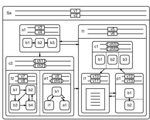
2.3 Example of a SpecC model . . . 34
2.4 Typical test bench model . . . 35
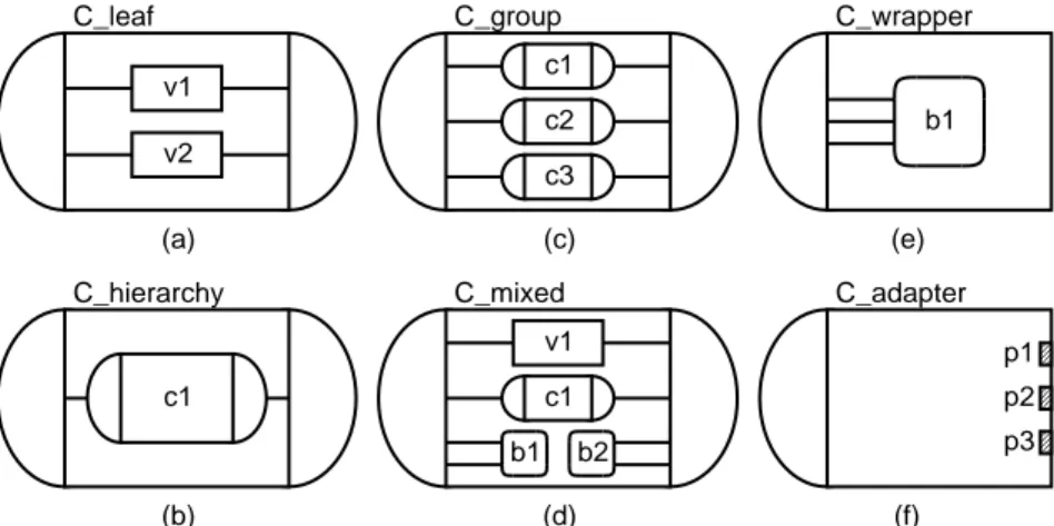
2.5 Behavior models . . . 36
2.6 Models of communication . . . 39
2.7 Channel models . . . 40
2.8 IP channel model . . . 42
2.9 IP wrapper model . . . 43
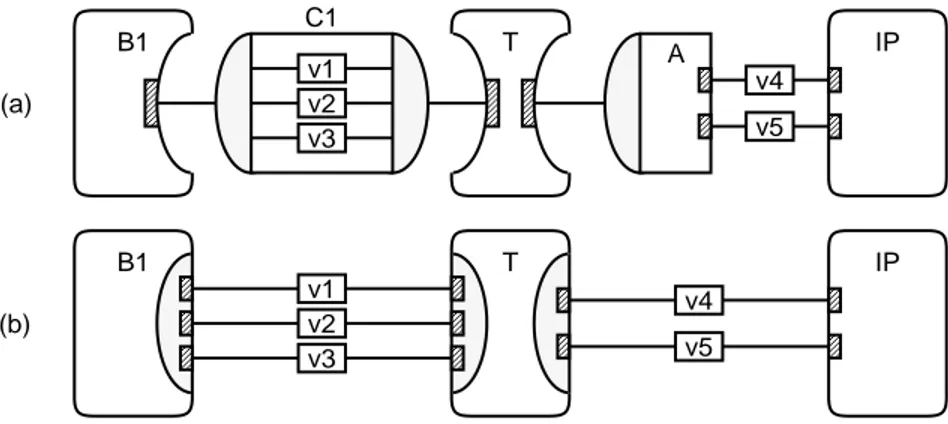
2.10 IP adapter model . . . 44
2.11 Wrapper inlining . . . 44
2.12 Adapter inlining . . . 45
2.13 Inlining with transducer . . . 45
3.1 SpecC system design methodology . . . 48
3.2 Specication model . . . 52
3.3 Generic system architecture . . . 56
3.4 Example of a system architecture . . . 57
3.5 Design example S1 before behavior mapping . . . 58
3.6 Design example S1 after behavior mapping . . . 59
3.7 Design example S1 after scheduling . . . 60
3.8 Design example S2 , initial specication . . . 61
3.9 Design example S2 before variable mapping . . . 62
3.10 Design example S2 after variable mapping . . . 63
3.11 Design example S3 before channel mapping . . . 64
3.12 Design example S3 after channel mapping . . . 64
xiii
3.13 Architecture model . . . 66
3.14 Design example S4 before communication synthesis . . . 69
3.15 Design example S4 after transducer insertion . . . 70
3.16 Design example S4 after protocol insertion . . . 71
3.17 Design example S4 after protocol inlining . . . 72
3.18 Communication model . . . 73
3.19 Implementation model . . . 75
4.1 Behavioral hierarchy . . . 80
4.2 Exception handling . . . 82
4.3 Comparison of language features . . . 84
4.4 Basic structure of a SpecC model . . . 89
4.5 Timing diagram example . . . 104
5.1 The SpecC design environment . . . 112
5.2 Design representation with the SIR . . . 115
5.3 SIR Application Programming Interface . . . 117
5.4 Program ow of the SpecC proling tools . . . 119
5.5 Program ow of the SpecC compiler . . . 122
5.6 Standard debugger use for SpecC programs . . . 123
5.7 Program ow of SpecC renement tools . . . 124
B.1 JPEG encoder with test bench . . . 179
C.1 Generic SIR design tree of level 1 classes . . . 186
C.2 Generic SIR design tree of level 2 classes . . . 187
List of Tables
1.1 System-level design projects in academia . . . 19
1.2 System-level design projects in industry . . . 20
5.1 Source components of the SpecC release 2.0.4 . . . 114
5.2 Development and implementation of the proling tools . . . 120
6.1 RT level IP examples . . . 133
6.2 System level IP examples . . . 135
B.1 SpecC tutorial examples . . . 176
B.2 Library example . . . 177
B.3 Composition of IP library components . . . 177
B.4 Communication examples . . . 178
B.5 Controller examples . . . 179
B.6 JPEG encoder example . . . 180
B.7 GSM vocoder example . . . 181
xv
Chapter 1
Introduction
The semiconductor roadmap [SIA97], published by the Semiconductor Industry As- sociation (SIA), estimates the design complexity for digital systems to continue to increase according to Moore's law [Ham99]. Applied to the design of embedded systems, Moore's law estimates the number of transistors on a chip to double every 18 months. The exponential growth of chip capacity is based on the continuing decrease in geometry size and increase in chip density.
In the next years, deep sub-micron design, dealing with process technologies of 0.18 m and below, will allow to integrate 10ths of millions of logic transistors on one chip. This makes it possible to implement complex embedded systems entirely on a single chip. System-on-Chip (SOC) designs will integrate system components including processor cores, memories and special-purpose custom logic blocks into a complete system tting on a single die.
SOC design is desirable especially for multi-media applications and portable devices where embedded systems save space, power and cost. In contrast to tradi- tional ASIC design, which implements one sub-system in application-specic hard- ware, SOC design consists of the integration and implementation of special-purpose, complex components which are interacting with each other. Typically, a SOC in- cludes one or more microprocessors, several peripheral units, memory blocks, and application-specic logic portions interconnected by on-chip busses.
While the availability of a huge chip capacity enables SOC designs, it, at the same time, signicantly raises the complexity of these systems. The increased complexity requires substantially more eort, more ecient tools and new methodologies for building such embedded systems. In fact, the complexity of SOC design is beyond the size that currently established electronic design automation (EDA) tools and methodologies can handle.
The SIA roadmap shows that a productivity gap exists between the available
1
chip capacity and the current design capabilities. While the chip capacity grows by 58% per year (according to Moore's law), the support provided by computer-aided design (CAD) tools is estimated to increase by only 21% each year [SIA97]. If this growing gap cannot be overcome, it will result in under-utilization of the available chip capacity and thus unnecessarily increase the cost of embedded systems.
In the past, automated hardware synthesis was used to bridge the productivity gap. Logic synthesis and recently behavioral synthesis, also known as high-level syn- thesis (HLS) [GDW
+91], supported designers in order to increase their productivity.
Unfortunately, the help of hardware synthesis is not sucient for SOC design, since embedded systems require more and more software content.
It should be clear that an increase in the design time for embedded systems is not an option in order to solve the productivity problem. The time-to-market is critical for the success or failure of a product in the market. Thus, it is necessary to develop and manufacture the next-generation product (and its embedded system) as quickly as possible in order to promote \product-on-demand". Ignoring the market pressures, which require to oer better products with more features for less money in shorter periods of time, is not acceptable.
The threatening under-utilization of available chip capacity due to the produc- tivity gap and the strong market pressures force the electronic industry to search for new design methodologies. More ecient EDA support is required in order to build successful SOC designs. This is the motivation for system-level design which is dened in the following section.
1.1 System-level Design
System-level design (SLD) addresses the problem of the increased complexity of embedded systems by raising the level of abstraction. In contrast to behavioral synthesis, which deals with the implementation of algorithms in application-specic hardware (ASIC design), system-level design focuses on the problem of mapping an abstract specication model of an entire system onto a target architecture (SOC design). As mentioned earlier, a typical target architecture consists of a set of processor cores, memories, peripheral units, and custom hardware blocks. These system components are interconnected by on-chip busses whose implementation is part of system-level design as well.
The cost-eective implementation of complex embedded systems requires a high
software (SW) content. Compared to the high cost of developing dedicated hardware
(HW), a software implementation is inexpensive. In addition, software can easily
be modied if requirements change or new features need to be added. However, a
software implementation may not be possible due to performance constraints. It is
1.1. SYSTEM-LEVELDESIGN
3 one task of system-level design to trade-o an inexpensive and exible software so- lution versus a high-speed hardware implementation. Therefore, system-level design is also referred to as HW/SW codesign.
Codesign is dened as the design of systems involving both hardware and soft- ware. The main task of codesign is the partitioning of a single system specication into hardware and software parts. Then, depending on whether a specic compo- nent is to be implemented in software or hardware, standard software technologies and established hardware design methods, respectively, are used for the nal imple- mentation of the component.
In general, any system consists of parts from dierent domains. Therefore, sys- tem design often is dened as to also include the mechanical domain in addition to the domain of electronics (see for example [CHM
+99] and [Sch99]). The inclusion of mechanical aspects extends the coverage of the system model compared to the real system. It also allows trade-os to be made between mechanical versus electronic implementation of certain features.
On the other hand, these orthogonal domains are quite independent in most cases and thus can be treated separately. This separation signicantly simplies the design tasks as well. Hence, in this work, system design is considered exclusively within the domain of electronics.
Furthermore, some system-level design environments explicitly support the spec- ication and use of analog and mixed signals. While this is useful for sub-systems, for example in the telecommunication area, the majority of embedded systems is specied completely digital. Also, the decision whether a signal is implemented as either analog or digital, can be viewed as an implementation issue that is resolved later in the design ow by back end tools. Within this work, system-level design targets on the design of digital systems [Gaj97], including hardware and software parts.
The system design ow usually starts from a formal, abstract specication of the intended design. After the specication has been validated for functional correctness, it is rened by a sequence of renement tasks which eventually map the initial specication onto a selected target architecture. Section 1.1.4 discusses in detail the steps in a typical system design process including architecture selection, partitioning, scheduling and communication synthesis.
A very important issue in system-level design is the reuse of predesigned, complex
components, often referred to as Intellectual Property (IP). In fact, the reuse of IP
is the main key to cope with the complexity involved with SOC design. In contrast
to redesigning a system completely from scratch, the use and integration of complex
components, which are predesigned (possibly by somebody else) and well-tested,
drastically reduces the design complexity. Thus, reuse of IP saves a great amount
of design and testing time and, hence, allows a shorter time-to-market.
While the idea of IP reuse promises great benets for system design, there are also problems to be solved. In order to allow easy and seamless integration in a new system, IP components need to be portable to dierent technologies and must provide standard or exible interfaces. Good documentation about the IPs functionality, its requirements with respect to the environment, and its performance and other metrics are required as well.
The reuse of IP must become an integral part in the system design methodology.
The selection, easy insertion and replacement of IP components (\plug-and-play") in the system must be directly supported by the design models, the tools and the languages being used throughout the design process. These and other issues involved with the reuse of IP are addressed in more detail in Section 1.1.5.
1.1.1 Levels of abstraction
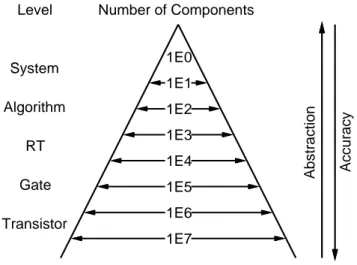
In computer science, a well-known solution for dealing with complexity is to exploit hierarchy and to move to higher levels of abstraction. This eectively reduces the complexity in terms of the number of objects to be handled at one time.
Abstraction Accuracy
Transistor Gate Algorithm
System 1E0
1E6 1E5 1E4 1E3
1E7 1E2 1E1
Level Number of Components
RT
Figure 1.1: Abstraction versus complexity
Figure 1.1 illustrates this for digital systems. An embedded system, which at
the lowest level consists of 10ths of millions of transistors, typically reduces to only
thousands of components at the register-transfer level (RTL). Furthermore, RTL
components are grouped together at the algorithm level. Finally, at the highest, the
so-called system level, the one system is composed of only few components which
include microprocessors, special-purpose hardware, memories and busses. From
1.1. SYSTEM-LEVELDESIGN
5 Figure 1.1, it is obvious that a complex embedded system is easier to deal with at the abstract system level than at the detailed gate or transistor level.
The level of abstraction is a trade-o with the level of accuracy. A high abstrac- tion level implies low accuracy, and vice versa. The design process of a new system usually starts from a highly abstract specication model and ends with a highly accurate implementation model which reects the real system with all its details.
The advantage of such a top-down approach is that all necessary design decisions can be made at an abstraction level where all irrelevant details are left out in the model. This allows the design tasks to work with a system model with minimum complexity.
The concepts of abstraction and hierarchy are closely related. In digital systems, hierarchy is inherent in the structure of a system. Every system is composed of a set of components, and each component is a (sub-) system that, again, is composed of (sub-) components. In other words, the terms system and component are recursively dened.
In order to break the recursion in this denition and to clearly identify the system and its components, it is necessary to name the current abstraction level. The abstraction level denes the type of the components used and, thus, also determines the system. For example, at the gate level, the components are logic gates and the system is the composition of such gates. One level below, at the transistor level, a single gate can represent an entire system that is composed of a set of transistors.
It should be pointed out that the term system, in general, refers to dierent things in dierent contexts. For example, a modern aircraft can be viewed as one single system or as a collection of thousands of systems. Within this work, unless stated otherwise, the term system refers to a digital, embedded system which can be implemented by use of application-specic hardware and software running on one or multiple processors.
Please note that this denition of a system is consistent with the term system- on-chip. It is also well-dened with respect to the abstraction level for SOC design, the system level. A precise denition of system-level design will be given in the following section by use of the Y-Chart.
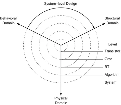
1.1.2 The Y-Chart
The Y-Chart [GK83], shown in Figure 1.2, is a conceptual framework which coor- dinates abstraction levels in dierent domains. This can be used to compare and classify dierent design tools and design methodologies.
The Y-Chart distinguishes three domains represented by three axes. A typical
design process starts from the behavioral domain which species the pure behavior of
the system without any implementation details, for example in form of program func-
Transistor Gate RT Algorithm System
Physical Domain
Behavioral Structural
Domain
Domain
Level System−level Design
Figure 1.2: System-level design in the Y-Chart
tions or mathematical equations. The design is then mapped onto an architecture in the structural domain. The structural architecture is composed of components, for example logic gates or RT components, depending on the level of abstraction.
Finally, an implementation of the design is manufactured in the physical domain.
The level of abstraction, as introduced in Section 1.1.1, is orthogonal to the domains. Starting from the center of the chart, the abstraction level, indicated by the dashed, concentric circles, increases from the transistor level up to the system level.
The Y-Chart allows to illustrate design ows and design tasks as paths on the chart. For example, a complete system design ow starts on the behavioral axis at the system level. After step-wise renement towards the center of the chart and mapping onto a structural and physical implementation, it nally ends on the physical axis at the transistor level.
On the Y-Chart, synthesis is represented by an arc from the behavioral to the structural axis. The denition of system-level design is indicated by the arrow in Figure 1.2. The task of system-level design is to synthesize a structural system architecture from a behavioral system specication.
As another example, high-level synthesis (HLS) is represented by an arc from
the behavioral to the structural axis on the RT level.
1.1. SYSTEM-LEVELDESIGN
7 Furthermore, the tasks of renement and optimization can be demonstrated on the Y-Chart as well. Renement is represented by an arrow on the behavioral axis from a high to a lower abstraction level. On the other hand, optimization can be represented as an arrow at any point in the chart which points back to its starting point. Thus, such optimization is a task that is performed in-place and can occur at any level in any domain.
Recently, the Rugby model [JKH99] was proposed as a new conceptual frame- work targeted to represent codesign tasks. In contrast to the Y-Chart, the Rugby model explicitly separates software and hardware design. Furthermore, the Rugby model distinguishes ve orthogonal dimensions, namely time, data, computation, communication and transformation. As such, the Rugby model is much more com- plex and not as abstract as the Y-Chart
1.
1.1.3 Models of computation
In order to design an embedded system, a formal model of the system is needed.
This section lists the models of computation which are commonly used in system- level design. For an in-depth discussion of these models, please refer to other sources in the literature. Good overviews, including detailed comparisons of the models, can be found in [GVN
+94, GZD97c] or [LS96, LSS99], for example.
Models of computation can be classied into language oriented and architecture oriented models. Among the language oriented models, the control ow graph (CFG) represents the control ow of a program (for example, if-then-else and loop statements) in form of a directed graph. A data ow graph (DFG) is a (typically acyclic) graph used, for example, to represent expression trees. CFG and DFG can be easily combined into a control data ow graph (CDFG), which is a CFG whose nodes contain DFGs. A CDFG is commonly used as an intermediate model for systems specied with imperative programming languages.
Architecture oriented models represent an abstraction of the target architecture for a system. The basis for these models is the nite state machine (FSM) model which is a popular model to describe control. A FSM consists of states and tran- sitions between the states. The output of a FSM is either state-based (Moore-type FSM), or input-based
2(Mealy-type FSM). A FSM model can be easily implemented in hardware as a controller consisting of a state register and a block of combinatorial logic.
The FSM model has several extensions. Combined with the DFG model rep- resenting computation, the nite state machine with datapath (FSMD) is a typical
1
The \beauty" of the Y-Chart lies in its simplicity.
2
The output of a state-based FSM depends solely on the current state, whereas the output of a
input-based FSM depends on the current state
andthe current input.
target model for behavioral synthesis. The implementation of a FSMD consists of a controller and a datapath. Very similar to the FSMD model is the nite state machine with coprocessors (FSMC) as dened in [JDK
+97].
In order to represent complete systems consisting of several concurrent process- ing elements, more complex models are required. For example, the codesign nite state machine (CFSM) model, described in [CGH
+93], can be used to represent a set of concurrent executing and communicating FSMs. Alternatively, hierarchy and concurrency can be explicitly added to the FSMD model. This results in the hierarchical concurrent nite state machine with datapath (HCFSMD) which allows to have sequential or concurrent sub-states in each state of the FSM.
Finally, programming language constructs can also be added. The program state machine (PSM) model, dened in [GVN
+94], is a HCFSMD whose leaf states contain program statements. The PSM is a powerful computational model that is used, for example, as the underlying model of the SpecCharts language [GVN93].
Many other models exist with focus on dierent features. The model of communi- cating sequential processes (CSP), described in [Hoa85], emphasizes communication.
The synchronous data ow (SDF) model is used in [LM87] to represent data ow intensive applications and digital signal processing. Petri nets, rst described in [Pet62], are used in several variants and provide a well-dened, formal background for the static analysis of systems.
The model of computation used for embedded systems design should meet certain requirements and objectives. First, it should be intuitive to understand so that it is easy to specify the intended system with the model. Second, it must be executable in order to allow early system simulation. Furthermore, the model should be veriable, in other words, it should provide support for formal verication. Finally, it must be synthesizable so that an implementation of the model can be obtained.
The models listed in this section achieve these goals more or less. It is not possible to decide which model of computation is best suited for the design of em- bedded systems. For the SpecC system, which is described later in this work, the PSM computational model was chosen. Since the PSM model is close to the target architecture, it simplies the development of CAD tools. The model also is easy to understand and sucient powerful for the large complexity of SOC design. The PSM model is directly supported by the SpecC language, the SpecC CAD tools, and the SpecC methodology.
1.1.4 System design process
The system design process starts with a specication of the intended design at a
high level of abstraction and ends with an implementation model that accurately
describes the implemented system and its components. In order to obtain the imple-
1.1. SYSTEM-LEVELDESIGN
9 mentation from the specication, a set of renement tasks is applied to the system model. This section denes the necessary tasks in a typical system design process.
Abstraction Accuracy
Design space Target model
Implementation models Refinement
Specification model
Figure 1.3: Design process using step-wise renement
Figure 1.3 illustrates a top-down design process using step-wise renement.
Starting at the top of the pyramid, the specication model is transformed by a sequence of design tasks into rened models. At each stage, the available design space, as indicated by the shaded triangles in Figure 1.3, has to be explored. The goal of this design space exploration is to make a good design decision that will lead to an implementation model close to the target.
Each design decision aects the subsequent one in the way that the available design space shrinks. Obviously, it is important to choose the right model from the set of possible alternatives so that the target stays well inside the design space.
Otherwise, if the decision is made in the wrong direction, the implementation will miss the target.
In general, each design task can be performed manually by designers or auto- matically by CAD tools. Also, both ways can be combined using semi-automatic renement. Typically, it is up to the designer to make the design decision. Then automated tools are used to actually perform the tedious renement with the design such that the decision made is reected in the rened model.
It should be noted that the terms specication and implementation are relative to
a particular design task or abstraction level. The implementation model generated
by one task usually serves as the specication model for the next task.
1.1.4.1 Specication
The specication of the intended system is the starting point for the design process.
The specication must meet several requirements. First, it should be complete. In other words, it should cover the entire design with all its features, its functionality and its requirements. On the other hand, the specication should also be abstract.
It should not include any premature implementation details.
Furthermore, it is required that the specication is captured unambiguously in a formal language so that it can be processed by automated tools. More specically, the specication must be executable so that simulation can be used to validate the functionality of the system from the beginning.
The specication is the rst formal and functional description of the system.
It serves as an initial model against which all subsequent, rened models will be compared.
1.1.4.2 Validation
In order to ensure the correctness of a system model, it has to be validated. Val- idation can be performed either statically by model analysis or dynamically by simulation.
As mentioned earlier, simulation requires the system model to be executable.
Simulation validates the functionality of the system model in terms of the outputs generated for given input vectors. At dierent levels of accuracy, it can also be used to check the correctness of communication, synchronization, and timing.
Simulation usually is performed by a software simulator running on a host work station. However, system simulation in software is typically several orders of mag- nitude slower than the real system, in particular at low levels of abstraction. Hence, the system can only be validated for a short period of simulation time and a small set of test vectors. If this is not sucient and more eort and higher cost are acceptable, rapid prototyping can be used to increase simulation speed by use of reprogrammable hardware, for example, eld programmable gate arrays (FPGA) [Ros97].
It should be emphasized that simulation only validates a system model for the given test vectors and therefore, unless exhaustive simulation is performed, does not cover all possible cases. In contrast to validation, verication yields a 100% test coverage. Formal verication is a static analysis technique which can be used to prove certain properties of the system model. Formal verication requires a well- dened, formal model and, because of its complexity, can usually only be applied to very small systems.
In order to evaluate characteristics of a system which are not directly observable
1.1. SYSTEM-LEVELDESIGN
11 from the model, estimation techniques can be used. The task of estimation is to quickly determine critical quality metrics of the system such as performance, power consumption, size, cost, and others. Estimation can be performed either statically by analysis of the system model, or dynamically during simulation, for example, by use of proling.
For estimation, there is a trade-o of accuracy versus time. The emphasis of estimation is on fast, rather than exact, system evaluation. Thus, the use of estima- tion enables the designer to make a reasonable design decision in short time. This is in contrast to a conservative approach which actually synthesizes all alternatives in order to make an optimal decision, as proposed in [Nie98], for example.
When nally a system has been manufactured, it must be tested for full function- ality and no manufacturing defects. The high complexity of SOC designs requires that the chip is prepared for its testing already during the design process. Typically, built-in self-test (BIST) and other techniques are used to allow testing of chips with IP cores [ZMD99].
1.1.4.3 Renement
After the system specication is captured and validated, it is the task of architecture exploration to allocate the system architecture, to partition the specication into hardware and software parts, and to map all parts of the design to the components in the architecture. During architecture exploration, estimation is used to determine the quality characteristics of the architecture under consideration. If the metric goals are not satised, the system is repartitioned or a dierent architecture or dierent components are selected. In the worst case, if no acceptable solution is found, the specication must be changed in terms of goals, constraints, or features.
It is the task of architecture allocation to determine the number and types of the processing elements (PE) and the connectivity for the system architecture. The com- ponents in the target architecture typically include processors, application-specic hardware, memories, peripheral units and IP cores. These components are inter- connected by system or local busses. All components and busses are selected from the component library.
Most parts in a system specication can be implemented in either software or hardware. It is the task of HW/SW partitioning to trade o an inexpensive software solution versus a high-speed hardware implementation. Typically, only performance- critical parts of the system are implemented in hardware and all other parts are compiled into software to be executed on the allocated processors.
In general, scheduling has to be performed for the software parts of the system,
since sequential processors can only execute one thread at a time. Scheduling de-
termines the order of execution for the tasks assigned to a processor. Scheduling
can be static or dynamic. A static schedule can be computed at design time if all constraints, including task execution times, delays, and dependencies, are known beforehand and do not change at run-time. Otherwise, dynamic scheduling must be used. In that case, the execution order for all tasks is determined dynamically at run-time, for example, by use of a real-time operating system (RTOS).
At the end of architecture exploration, each object in the specication is mapped to a particular hardware or software component. The quality of this mapping de- pends very much on the granularity of the objects. A coarse grained granularity, which, for example, considers entire processes as smallest, indivisible units, simpli- es the renement tasks since less objects need to be handled, but also limits the implementation options. On the other hand, a ne granularity enables more options allowing a possibly better implementation, but also increases the complexity and, thus, the renement time.
After architecture exploration, communication synthesis must be performed.
This includes the selection of communication protocols for the selected busses, hard- ware interface synthesis, and software driver generation. More specically, accesses to data, which is assigned to a dierent PE, must be converted to remote procedure calls (RPC). Then, the RPCs can be implemented by use of the native bus protocol provided by the bus connecting the PEs. For hardware, interfaces need to be syn- thesized, and for software, device drivers must be generated. In case busses with dierent protocols need to be connected, protocol transducers must be inserted. In summary, the task of communication synthesis is to rene the abstract communi- cation between the components in the architectural model into an implementation using the actual bus protocols.
The system-level design process is completed with the back end. The task of the back end is to make the rened system model available to established design methodologies for behavioral synthesis and standard software design. In order to allow a seamless integration, it is important that the output generated by the back end can be used without modication as input to the subsequent tools.
For the software parts of the system, program code, for example C or assembly code, is generated so that standard compiler, assembler and linker tools can be used for the software implementation. If available, a retargetable compiler can generate code for all the allocated processors. Otherwise, a processor-specic tool set is needed for each type of processor in the system.
For the hardware parts, a synthesizable hardware description is generated, typi-
cally in VHDL or Verilog. This description can then be fed into high-level synthesis
tools in order to implement the custom hardware.
1.1. SYSTEM-LEVELDESIGN
13
1.1.4.4 Methodology
In the previous sections, the typical tasks used in the system-level design process have been discussed. It must be emphasized that most of these tasks are interde- pendent. Moreover, there are cyclic dependencies. For example, the architecture allocation heavily inuences the partitioning task, and vice versa. Also, timing constraints are input and output for both scheduling and communication synthesis.
Because of these dependencies, there is no sequence of tasks which guarantees an optimum solution.
A heuristic solution to this problem uses an iterative approach. A set of tasks is repeated until an acceptable solution is found. The decision, whether a solution is
\good enough" to proceed to the next task, is made by the system designer based on estimation data and his experience.
However, the design tasks must be supported by CAD tools and CAD tools place restrictions on the order they are executed. Thus, the system designer has to follow the guidelines under which the CAD tools were developed. Such a set of guidelines, which rene the abstract specication model into a detailed implementation model ready for manufacturing, is called a methodology.
A top-down methodology starts with a specication at the highest level of ab- straction and moves down to lower levels while step-wise rening the model. With each step, the design model becomes a more accurate representation of the nal implementation.
On the other hand, a bottom-up methodology starts from the lowest level, com- posing components together. These composed components then can be used in the next step to build even more complex components.
Both methodologies can be combined in order to achieve the best productivity.
Usually, the top-down methodology is used until the system is decomposed into components which can be selected from the component library. The component library, on the other hand, is built using the bottom-up strategy.
With this combined approach, only the top-down phase aects the crucial time- to-market for the product, because the component library can be built beforehand.
Thus, the key to a short design time enabling \product-on-demand" is the use of IP components, which are predesigned and can be easily integrated in order to build the product. The system design methodology, which is based on the integration of IP components, is called IP-centric [GDZ99a, GDZ99b].
1.1.5 Intellectual Property
As stated earlier, the reuse of IP is a key issue in SOC design. In fact, it is considered
a paradigm shift that can be compared to the introduction of high-level synthesis a
few years ago. This section elaborates on IP components and the benets, problems and requirements with IP reuse.
1.1.5.1 IP components
At the system level, predesigned components are frequently called IPs. IP compo- nents are independent processing elements, in other words, they have their own ow of control and interact with the other system components via the system busses.
Unlike full-custom components, which are synthesized from scratch specically for the application, IP components are selected from an IP library and are xed or allow only limited customization.
Typical IP components include memories, processors, and industry standard cir- cuits. Memory IPs, like RAM and ROM blocks, can usually be customized in their size, whereas processor IPs come typically as xed cores. Processor IPs include embedded micro-controllers, general-purpose, and digital signal processors (DSP).
Special-purpose IPs implement industry standards, for example, encoding and de- coding algorithms like MPEG, JPEG, etc., or communication devices like PCI or VME bus interfaces.
IP components can be categorized into hard and soft IPs. Hard IP components are developed by use of a standard design process and are fully implemented in a specic technology. In particular, for hard IPs, there is a physical representation of the layout, for example, in form of a GDS-II le [KB98]. Since hard IPs are fully implemented, their performance characteristics and other metrics are very accurate and predictable. However, hard IPs are inexible and limited to a specic target technology.
Soft IP components, in contrast, are very exible IPs which come typically in form of synthesizable RTL code. Usually, soft IPs can be parameterized or are user- congurable in terms of data size, features, etc. Since soft IPs are synthesizable, they can be implemented in any target technology as well. However, the implemen- tation metrics of soft IPs are not as predictable as for hard IPs, because the nal implementation has yet to be synthesized.
IP components can also be classied into internal and external IPs. Since the process of developing the system is decoupled from the development of the IP com- ponents, these tasks can be performed independently by separate design teams in possibly dierent companies. Internal IPs are developed inside the same company which builds the system. Typical internal IPs include legacy designs which can be reused from former products that have been proven to be successful.
The use of external IP is part of a new business model in the EDA industry.
External IP components are developed and provided by IP providers outside the
company building the system. While the system house, also called IP integrator, can
1.1. SYSTEM-LEVELDESIGN
15 focus on the problem of the system specication, integration and implementation, IP vendors develop and oer the required IP components. With this approach, the system house benets from a large library of optimized, well-tested and well- documented components which are available when needed. The IP providers, on the other hand, can take advantage of their expertise in specialized design areas without the need to build and sell complete systems. This business model works well because, in many cases, it is cheaper for the system house to purchase an IP component as to invest time and money to develop it from scratch.
1.1.5.2 IP reuse
The reuse of predesigned components is well-known in the EDA. For example, at the RT level, reuse includes the instantiation of components from the RTL library, such as registers, multipliers, arithmetic-logic units (ALU), etc. Similar to IPs, the components in a RTL library can be internal legacy components or external components supplied by another company.
The advantages of reuse are similar at the RT and the system level. At both levels, reuse of components drastically reduces the time and the cost of the de- sign because the reused components are already designed, optimized, and tested.
However, in order to exploit these benets, several problems have to be overcome.
The main two problems involved with design reuse are component matching and component integration. First, the task of matching is to nd a corresponding counterpart in the component library for a part of the design specication. A component can only be used in the implementation, if it matches the functionality and meets the constraints in the specication.
Then, the task of component selection is to choose one component from the set of matching components which best meets the design goals. Typical design goals are minimal cost or best performance.
Finally, when a suitable component is chosen, it must be integrated with the rest of the design. The task of integration is to ensure that the component is properly connected and controlled so that it cooperates with the other system components and works with the right data at the right time.
Component matching and integration are more dicult at the system level than at the RT level because of the higher level of abstraction. At the RT level, the behavioral and structural models of the components are close to the behavioral specication so that mapping and integration are usually straightforward.
For example, the behavioral model of an adder is simply an add operation in-
dicated by a plus sign. The structural model is a component with two bit vector
input ports and one bit vector output port. With these models, it is easy to map
an addition onto an adder component by feeding the left and right arguments into
the input ports and reading the result from the output port .
At the system level, however, the tasks of component matching and component integration are not as straightforward because the behavioral and structural models of system components are much more complex.
The functionality of both, the system specication and the IP components, is described by algorithms rather than primitive arithmetic operations. Hence, IP matching essentially has to deal with the comparison of algorithms. Whether two algorithms match, however, is undecidable in the general case. Therefore, IP match- ing requires special handling by the tools
4or the help of the designer.
The integration of IPs includes similar problems. Instead through plain ports, IP components usually communicate via non-trivial interfaces by use of possibly complex communication protocols. Hence, IP integration typically requires interface synthesis and protocol translation to be performed.
While the matching, selection and integration of IP components are tasks per- formed by system integrators, IP providers have to deal with the task of IP protec- tion which is discussed in the following section.
1.1.5.3 IP protection
Since the business of IP vendors depends on selling their intellectual property to other companies, IP providers have to protect their IP from being copied, modied, or reverse-engineered. IP protection addresses the security issues for external IPs.
In general, IP components are covered by a copyright and can be further pro- tected by legal contracts and non-disclosure or non-distribution agreements. How- ever, it is usually very dicult to detect and to prove that an IP is used without permission. Therefore, technical measures are taken in addition to legal guarantees.
For hard IPs, protection can be easily achieved by keeping the nal implementa- tion with the IP provider. This works well if the IP is provided by the same silicon vendor who also performs the nal layout and manufacturing of the system. Instead of the real implementation, the system integrator is supplied with simulation mod- els and estimation data of the IP. With these models, the system can be developed without the need for the real IP. Typically, the deliverables for a hard IP include simulation and timing models at dierent levels of abstraction, performance, power, and other metrics, a oor plan model, and comprehensive documentation about the functionality and interface specication of the IP [KB98].
3
Given a properly annotated component library, matching and integration is not signicantly more dicult for other RTL components.
4
For example, the matching of IP components could be indicated by use of a naming convention
or some form of annotation recognized by the CAD tools.
1.1. SYSTEM-LEVELDESIGN
17 For soft IPs, a dierent approach is necessary. Since the nal implementation will be synthesized by the system integrator, the complete, synthesizable model must be made available. In order to still hide the implementation or algorithm details, the IP can be provided in precompiled format without source code. This is basically the same, well-known idea used in the software business to protect proprietary code from being reverse-engineered.
Watermarking can also be used for IP protection. This technique inserts a unique identier, a so-called watermark, into the component. Such a watermark is typically hidden and dicult to remove. The existence of a watermark ensures that the component can always be identied. Watermarking can be easily applied to hard IPs [KLM
+98], but is dicult for soft IPs since it must be ensured that the watermark is not lost during synthesis.
1.1.5.4 IP requirements
This section summarizes the requirements for successful reuse of IP. Dierent re- quirements apply to the components, the methodology, the design model, and the tools being used in system level design.
In order to be reusable, IP components must provide support for IP matching, selection and integration. IP matching requires a clearly specied functionality.
For IP selection, accurate quality metrics are needed, such as performance, power consumption, size and cost. In order to allow seamless IP integration in a system, IP components must provide standard or exible interfaces. In other words, the IP interfaces and the communication protocols used must be clearly specied.
Furthermore, IP components need some form of protection and should be highly optimized and well-tested. In order to increase the reusability, IPs should also be customizable to dierent environments and portable to dierent technologies. The deliverables for IP components include simulation models at dierent abstraction levels, quality metrics and comprehensive documentation [KB98, SK
+99].
The system design methodology must be IP-centric. In other words, IP reuse must be an integral part of the methodology. The methodology must encourage the reuse of IP by use of guidelines and IP-centric models. Last but not least, the methodology must be supported by suitable tools.
Well-dened, IP-centric models are required for the design and component rep-
resentation throughout the design process. The design model must allow the easy
insertion and replacement of IP components (\plug-and-play") at any time in the
design process. This requires that the model clearly separates communication and
computation in the design. This ensures that communication and computation
portions can be clearly identied and easily replaced with dierent communication
protocols or computation algorithms.
Finally, tools are required to support the user with design maintenance and re- nement. System-level tools must recognize and support IP components. While design decisions usually are made by the system designer, CAD tools are needed for all tedious and error-prone tasks during the design process, including speci- cation capture, architecture exploration, communication synthesis, and hand-o to semiconductor manufacturing.
This work addresses the issues of system-level design in general, and, in partic- ular, the problems involved with the reuse and integration of IP components. An IP-centric methodology is presented which is based on well-dened design models and a language that specically supports the requirements of system-level synthesis.
1.2 Related Work
This section contains a brief overview about related work in system-level design.
While there are eorts, such as the virtual socket interface alliance (VSIA) [BS99], which address general system design issues like the denition of SOC de- sign, system data formats, IP interfaces and modeling guidelines, the majority of interesting projects resemble actual design systems. A subset of such systems for codesign and system-level design is presented in the following section.
Furthermore, Section 1.2.2 lists traditional languages which are commonly used for software, hardware, and system development.
1.2.1 Design systems
For system-level design and codesign, promising approaches and methodologies have been proposed in the academia as well as in the industry. A set of interesting tools and design environments has already been developed.
Table 1.1 lists promising system-level design projects developed by universities.
Furthermore, a set of commercial tools and design systems is shown in Table 1.2. It should be noted that many commercial tools have evolved from university projects.
For example, CoWare and SystemC
5originated in academia
Although it is very dicult to classify all these approaches, the main emphasis for each project is noted in Table 1.1 and Table 1.2. Most systems try to cover many aspects of system-level design, but have their strength in the area indicated in the tables. Each of these projects really focuses only on a subset of the tasks.
Furthermore, the target architectures addressed by the tools are, in many cases, quite specic and do not cover the whole design space.
5
SystemC originally is Scenic.
1.2. RELATED WORK
19
Project University Main Focus
Chinook Univ. of Washington Communication synthesis Cobra Univ. of Tubingen Rapid prototyping
Cool Univ. of Dortmund Synthesis Cosmos TIMA Laboratory Synthesis Cosyma TU Braunschweig Synthesis
JavaCAD Univ. of Bologna Networked framework JavaTime UC Berkeley Simulation
Lycos TU Denmark Synthesis
Polis UC Berkeley Formal specication Ptolemy UC Berkeley Simulation
Scenic UC Irvine Simulation
SpecSyn UC Irvine Exploration
Tosca Politecnico of Milan Synthesis
Vulcan UC Irvine Synthesis
Weld UC Berkeley Networked framework Table 1.1: System-level design projects in academia
The SpecC design environment described in this work compares well with the set of academia projects listed in Table 1.1. As described later, the SpecC system addresses system specication, simulation, as well as synthesis. However, the main focus of SpecC is design modeling, which is described in detail in Chapter 2.
System-level design and codesign systems can be classied by either homoge- neous or heterogeneous specication.
Homogeneous specication: A single language is used for specifying the system including hardware and software parts.
Heterogeneous specication: Dierent languages are used for specifying the system, for example, VHDL (for hardware) and C (for software).
Examples for both types of systems are given in the next two sections.
1.2.1.1 Homogeneous specication
Chinook: Chinook
6[COB95] is a codesign tool that addresses in particular in- terface and communication synthesis. Cosimulation and cosynthesis with timing
6
Online information about Chinook is available at:
http://www.cs.washington.edu/research/projects/lis/www/chinook/
Project Company Main Focus COSSAP Synopsys, Inc. Capture
CoWare CoWare, Inc. Interface synthesis Eaglei Synopsys, Inc. Simulation
SystemC Synopsys, Inc. Simulation Seamless Mentor Graphics Corp. Simulation
SPW Cadence, Inc. Capture
XE Y Explorations, Inc. Reuse
Table 1.2: System-level design projects in industry
constraints are addressed as well. Chinook is targeted at the design of control- dominated, reactive systems. The system specication is homogeneous since Verilog is used as the only input language.
Tosca: Tosca
7[BFS95] is a synthesis-oriented system which, just as Chinook, tar- gets at the design of reactive real-time embedded systems. Tosca is an early, prag- matic approach to codesign automation of control-dominated systems. The target architecture consists of a single micro-processor core and several ASICs. Assembly code is generated for execution by the processor and the ASICs are described in VHDL.
Cool: In contrast to the control-dominated systems Chinook and Tosca, Cool [Nie98] is a codesign system for data-ow dominated embedded systems. With Cool, a system is specied in VHDL. The synthesis result consists of assembly code for possibly multiple processors and synthesizable VHDL for possibly multiple ASICs. Cool emphasizes a precise partitioning approach using mixed integer linear programming (MILP) based on exact cost and performance measures.
Vulcan: Vulcan [GM96] is an early, synthesis-oriented system with homogeneous specication. HardwareC is used as description language for both hardware and software. Vulcan starts with a complete hardware solution (everything is imple- mented in ASICs) and then iteratively moves tasks to a single CPU in order to reduce the costs while obeying the given performance constraints.
7
Online information about Tosca is available at:
http://www.cefriel.it/eda/projects/tosca/html/default.htm
1.2. RELATED WORK
21
Cosyma: Cosyma [EHB93, HE97, OBE
+97] is a synthesis-oriented system focus- ing on hardware/software partitioning. The system is specied in C x , a variation of the C language. The target architecture consists of one RISC processor with a coprocessor implemented in an ASIC. In contrast to Vulcan, Cosyma starts with an all-software implementation (the complete system is executed on a single CPU) and then moves tasks to the ASIC if the performance constraints are not satised.
Lycos: Just as with Cosyma, the target architecture of Lycos [MGK97] is an embedded micro-architecture consisting of one processor with a coprocessor imple- mented as an ASIC or FPGA. With Lycos, the system is homogeneously specied in either VHDL or the C language. The main emphasis of Lycos is the partitioning task.
Cosmos: Cosmos [VRD
+97, IAJ94] targets at the development of multiprocessor architectures using a set of user-guided transformations on the design. In contrast to Cosyma and Lycos, the target architecture consists of possibly multiple processors.
In Cosmos, the system is specied in SDL. The generated output consists of VHDL for the hardware, and C for the software parts of the system. It should be noted that the Cosmos system has been extended to support cosimulation with parts in the mechanical domain which are described in Matlab [CHM
+99].
SpecSyn: SpecSyn [NVG91, GVN93, GVN
+94] is a codesign environment for sys- tems specied in SpecCharts, which is a front end language for VHDL. The main focus of the SpecSyn system is design estimation and design space exploration. The target architecture consists of multiple processors, ASICs and memories, connected via system busses.
Scenic/SystemC: The academic Scenic project [GL97, LTG97, GKL99] recently has been commercialized in form of the SystemC
8initiative. In Scenic (or Sys- temC), the design system is described with the software programming language C++. Required modeling features not present in the language, like, for example, concurrency and synchronization, are specied by use of special methods imple- mented in standard classes provided with the Scenic libraries. Although Scenic targets also at system synthesis, its main focus is simulation. In other words, Scenic is a simulation-oriented system, in contrast to the synthesis-oriented systems listed earlier.
For a more detailed description of Scenic including a comparison with the SpecC system described in this work, please refer to [DG98].
8