IE3
Modul Electricity
Induction
In this experiment, the phenomenon of induction will be examined. In- duction is one of the most intriguing effects of the theory of electricity.
Induction is not only of enormous interest, because the transition from electrostatics to electrodynamics is only with their help, and thus, the phenomenon of electromagnetic radiation can be examined, but also due to the great technical significance of this phenomenon.
Versuch IE3 - Induction
In this experiment, the phenomenon of induction will be examined. Induction is one of the most intriguing effects of the theory of electricity. Induction is not only of enormous interest, because the transition from electrostatics to electrodynamics is only with their help, and thus, the phe- nomenon of electromagnetic radiation can be examined, but also due to the great technical sig- nificance of this phenomenon.
c
AP, Departement Physik, Universität Basel, February 2020
1.1 Preliminary Questions
• How is the induction law of Faraday defined?
• What is meant by the term magnetic flow and of which quantities will this rule depend from. What is the unit of the magnetic flux?
• What does Lenz’s law mean? Which underlying fundamental principle of nature is this based on?
• Research 5 technical applications, which the effect of induction is at the basis of.
• Regarding your basic knowledge, if necessary, repeat differentiation (Figure) of func- tions of one variable, and the associated calculation rules (product and chain rule.)
• What is meant by partial differential and what constitutes a total differential?
1.2 Theory
1.2.1 The Electromagnetic Induction
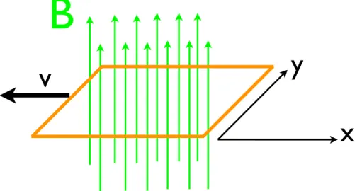
To understand the phenomenon of induction, it is of great help, to introduce a new physical quantity, which has not been previously used. Let us consider an ordinary conductor loop, which a steady electric current flows through. It is known, that this causes a steady stream of a magnetic flux densityB, which often simply is called the magnetic field. The direction and amount of the magnetic flux density can be calculated by means of the law of BIOT-SAVART and an example is shown in Figure 1.1.
The observed conductor loop encloses an area A. The introduced quantity is defined as the product of the area Aand the flux density B, which flows through the loop, this quanity is called MAGNETICFLUX:
Φ=B·A (1.1)
The corresponding physical unit is the Weber, written 1 Wb. It should be noted that this formulation is a special case for the case that Bis perpendicular to A. Generally, it must be integrated over the corresponding area, it gives then1:
Φ=
Z
A
~B dA~ (1.2)
Furthermore, we will confine ourselves at this point to steady flows, that is, the current through the conductor loop is not considered a function of time and thus, the resultant mag- netic flux densityBis also not a function of time. Alternatively, you can also assume that the magnetic flux density of permanent magnets caused from that and is required with no current in the conductor loop, this is also what is in the experiment to be the case. However, let us now assume that the area enclosed by the conductor loop Surface is not constant but varies as a function of time. This then results in a temporal change of magnetic flux.
dΦ
dt = −B·dA
dt = −B·
∂A
∂x
∂x
∂t + ∂A
∂y
∂y
∂t
=−B·y·∂x
∂t (1.3)
1This is a so-called surface integral, which in the course of your lectures in mathematics, you will get to know better.
3
Here, a rectangular conductor loop of area A = x·y was assumed and the deformation or movement is to take place only in the x-direction. Thereby, it is assumed, that the area Ais reduced, thus the negative sign.
B
y
x v
Figure 1.1: Exemplary illustration of a rectangular loop which the magnetic flux densityBis penetrated. By moving the conductor loop in the x-direction, it is reduced when penetrated byBsurface.
Now consider the specifically above-mentioned case that the magnetic flux density is gener- ated by a permanent magnet and no current flows in the conductor loop. In this case, an open conductor loop can also be used. The electrons in the conductor loop move together with the loop itself in the direction of the x-axis. Thus, the electrons move through theB-field and acts on them with a Lorentz force. Due to this Lorentz force, the electrons move in the wire loop until an opposing electric field is built up, which compensats the Lorentz force. On the ends of the loop, to tap a voltage which is so-called INDUCTION VOLTAGE.
From numerous experiments, already executed with Faraday, is known that this INDUCTION VOLTAGEis proportional to the change of the MAGNETIC FLUXas:
Uind=−dΦ
dt (1.4)
Here, the sign is of particular importance, because the induced voltage, according to the LENZ
LAW, needs to counteract the inducing cause. The is of enormous importance, since otherwise the energy conservation is not given.
For the example considered here, it is obtained by substituting Equation 1.3 in Equation 1.4:
Uind= B·y·v (1.5)
This is the special shape of the induction voltage that can be used in this experiment. A more general treatment may be read at the end of this manual or in the cited references.
1.3 Experiment
In this experiment, the conductor loops of different widths are mounted on a rail, and can be moved by means of a motor. Permanent magnets under this rail provide the required mag-
4
netic flux density. In the experiment, the velocity with which the rail is pulled, can be varied.
However, no absolute measurement of this velocity is necessary, but with a connector socket, the motor can have a constant speed of the motor, where the speed will be varied in the ratio 1:2:4 4.
The strength of the magnetic flux density may also be varied, namely by the number of per- manent magnets used, which are attached to the apparatus.
1.3.1 Equipment
Components Number
Induction unit with conductor loop 1
Magnet 12
Motor 1
Control and regulating unit 1
Microvoltmeter 1
1.3.2 Experimental Setup and Adjustment
First, the setup with the appropriate number of magnets must be fit. On the induction unit, there is a label indicating at which point the magnets are to be positioned (for configurations withn = 2, 3, 4, 5, 6) as pairs of magnets. Make sure the magnets are all installed at the same polarity.
Check whether the motor and the regulating unit are correctly connected to each other and if the mains are connected.
Figure 1.2: Exemplary test setup with a)slot on the coupling, in which the wire is threaded to, b) the end point of the rail, c) guide rail, d) rail, e) position of incorporated magnets, f)shielded cable, and g)bridge plugs
Furthermore, it should be checked whether the provided string is correctly fit on the rail and the motor as well. Before starting the experiment, your setup shoul be inspected by an assis- tant again.
1.3.3 Experimental Procedure
• Measurement ofUindas a function of velocity: This measurement is carried out with six pairs of permanent magnets. Put a jumper plug so that the widest conductor loop (y = 4cm) is used. Now select the smallest axis on the coupling of the experiment motor. Regulate the velocity of the motor so that the induced voltage on the micro- voltmeter is about 50µV (the gain factor/gain should be in accordance with the expected voltage selected). Place the engine off, but without changing the velocity! Drive the sled back to the starting position and repeat and measure the exact induction voltage. This
5
measurement is 10 times repeated and then calculate the mean and standard deviation.
Repeat this series of measurements for the middle and the major diameter axis.
• Measurement of Uind as a function of the width of the y conductor loop: Repeat the measurement described above for the other two available widths of the conductor loop, and remember to put to the bridge plugs accordingly.
Specifically, you have to make 10 measurements for each velocity and for each width, in order to have at the end 9 combinations of widths per velocity and overall 90 measure- ments.
• Measurement ofUindas a function of magnetic flux densityB: Use the widest conduc- tor loop withy = 4cm and the largest axial diameter. Measure the induction induced emf as a function of the number of pairs of permanent magnets usedn = 1, 2, 3, 4, 5, 6.
For each value of n, the resulting induced voltage is measured 5 times. Then calculate again the mean and standard deviation.
1.3.4 Tasks for Evaluation
• Illustrate the measurement rows in the graph and fit an appropriate function to your data. Think about this, what functional dependence would be achieved, according to the theory? Discuss your results and possible uncertainties and experimental and theo- retical sources of error. Describe the theory in the manual using the the consideration in the experiment case exactly?
Literature
• Demtröder Band 2 - Elektrizität und Optik, 6. Auflage: Kapitel 4 Zeitlich veränderliche Felder
• Gerthsen Physik, 22. Auflage 22 oder neuer: Abschnitt 7.4Induktion
6
Appendix
A.1 Maxwell’s Equation and Faraday’s Law of Induction
Plot electrodynamics, including the marginal cases of electrostatics and aagnetostatics de- scribed by the MAXWELL-EQUATIONS. It is made of a system of 4 linear, partial differential equations of 1st order:
∇ ·~E = ρ
ε0 (A.6)
∇ ·~B = 0 (A.7)
∇ ×~E = −∂~B
∂t (A.8)
∇ ×~B = µ0~j+µ0ε0∂~E
∂t (A.9)
The first of these equations represents COULOMB’S LAW and replaces them in electrostatics and mathematically expresses the electrical charges of the origin of the electrical field. One says that the electric charge is the source of the electric field. The second equation is known as GAUSS LAW(for magnetic fields). It expresses that there are no magnetic monopoles and therefore, the field lines of the magnetic field must always be closed. One says that the mag- netic flux density is source free. The fourth of these equations is AMPERE’S LAW. It states that currents (including Maxwell’s displacement current) are the source of magnetic fields or magnetic flux density.
The third law is treated as FARADAY’S LAW OFINDUCTION in this experiment. It states that a change in the magnetic flux density is an electric (vortex) generated field. This may seem to be something completely different, as discussed in the effect of the above experiment, but this is not the case. If one uses the described integral theorems from mathematics (set of Gauss and Stokes), one can take the differential of Maxwell’s equations, and write in integral form, as well as the Faraday’s Law of Induction.
I
∂A
~E·d~s= −d dt
Z
A
~B·dA~ (A.10)
Here, you can again see Eqs.1.4 und 1.2 from the theory section of the instructions.
7