Late Holocene to Recent aragonite-cemented transgressive lag deposits in the Abu Dhabi lagoon and intertidal sabkha
Y U Z H U G E * , C H E L S E A L . P E D E R S O N * , S T E P H E N W . L O K I E R† ,
J A N P . T R A A S * , G E R N O T N E H R K E‡, R O L F D . N E U S E R * , K A T J A E . G O E T S C H L§ and A D R I A N I M M E N H A U S E R *
*Institute for Geology, Mineralogy and Geophysics, Ruhr-Universit€at Bochum, Universit€atsstrabe 150, Bochum, 44801, Germany (E-mail: adrian.immenhauser@rub.de)
†School of Ocean Sciences, Bangor University, Bangor, Gwynedd, LL57 2DG, UK
‡Alfred Wegener Institute for Polar and Marine Research, Am Handelshafen 12, Bremerhaven, 27570, Germany
§Institute of Applied Geosciences, Graz University of Technology, Rechbauerstrasse 12, Graz, 8010, Austria
Associate Editor – Hairuo Qing
ABSTRACT
Modern cemented intervals (beachrock, firmgrounds to hardgrounds and concretionary layers) form in the lagoon and intertidal sabkha of Abu Dhabi.
Seafloor lithification actively occurs in open, current-swept channels in low- lying areas between ooid shoals, in the intertidal zone of the middle lagoon, some centimetres beneath the inner lagoonal seafloor (i.e. within the sedi- ment column) and at the sediment surface the intertidal sabkha. The concept of ‘concretionary sub-hardgrounds’, i.e. laminar cementation of sediments formed within the sediment column beneath the shallow redox boundary, is introduced and discussed. Based on calibrated radiocarbon ages, seafloor lithification commenced during the Middle to Late Holocene (ca 9000 cal yr BP), and proceeds to the present-day. Lithification occurs in the context of the actualistic relative sea-level rise shifting the coastline landward across the extremely low-angle carbonate ramp. The cemented intervals are inter- preted as parasequence boundaries in the sense of ‘marine flooding surfaces’, but in most cases the sedimentary cover overlying the transgressive surface has not yet been deposited. Aragonite, (micritic) calcite and, less commonly, gypsum cements lithify the firmground/hardground intervals. Cements are described and placed into context with their depositional and marine diage- netic environments and characterized by means of scanning electron micro- scope petrography, cathodoluminescence microscopy and Raman spectroscopy. The morphology of aragonitic cements changes from needle- shaped forms in lithified decapod burrows of the outer lagoon ooidal shoals to complex columnar, lath and platy crystals in the inner lagoon. Precipita- tion experiments provide first tentative evidence for the parameters that induce changes in aragonite cement morphology. Data shown here shed light on ancient, formerly aragonite-cemented seafloors, now altered to diagenetic calcites, but also document the complexity of highly dynamic near coastal depositional environments.
Keywords Carbonate cement, early-marine cementation, Gulf, hardgrounds, seawater chemistry.
©2020 The Authors.Sedimentologypublished by John Wiley & Sons Ltd on behalf of 1
International Association of Sedimentologists
Early diagenetic cementation of carbonate- dominated sediments at the seafloor is a com- mon process throughout much of Earth’s his- tory (Clari et al., 1995; Christ et al., 2015).
Lithification of sediments by various cements leads to the formation of firmgrounds and hardgrounds described for a broad range of marine environments (Kennedy & Garrison, 1975; Brett & Brookfield, 1984; Mutti & Ber- noulli, 2003; De Boever et al., 2017). The con- ventional view is that early cementation occurs at, or close to, the sediment–water interface (Kennedy & Garrison, 1975), and is typically inferred to reflect low rates or cessation of sed- iment deposition (Shinn, 1969; Mutti & Ber- noulli, 2003; cf. ‘omission surfaces’, F€ollmi, 2016). The majority of previous studies of mar- ine firmground/hardground formation have dealt with ancient deposits (ca 750 of a total of ca 950 papers, Christ et al., 2015), where there is significant potential for the loss of pri- mary depositional information (Strasser, 2015).
This is particularly true for hardgrounds lithi- fying predominantly aragonitic sediments by means of aragonitic fabrics. During subsequent burial diagenesis, these features often become diagenetically overprinted and are difficult to recognize. Although a range of hydrodynamic, chemical and biological mechanisms have been proposed as controls for firmground and hard- ground formation and alteration (Given &
Wilkinson, 1985; Tribble, 1993), significant dif- ficulties remain in defining which of these are the primary factors influencing the develop- ment and evolution of hardgrounds, and their associated cement fabrics and biota (Burton, 1993; Vousdoukas et al., 2007).
The limited current understanding of the com- plex interaction of processes relevant in hard- ground formation and alteration calls for focused studies of actualistic in situ seafloor cementation where the direct observation of pro- cesses and products is possible. Despite some criticism suggesting that the Present is at best the key to the Pleistocene (Neumann & Land, 1975), sedimentologists have turned to actualis- tic carbonate depositional environments such as the Florida and Bahamas region, Barbados, Ber- muda, the Persian (Arabian) Gulf (hereafter referred to as the ‘Gulf’), the Red Sea, the Gulf of Mexico and the Mediterranean [refer to Christ et al.(2015) for a detailed overview of published
grounds. However, the majority of work is pre- dominantly descriptive, and focuses on palaeoecological aspects, or deals with isolated outcrops, particularly from intertidal and lagoon environments (Purser, 1969; Shinn, 1969; Fried- man et al., 1974; Hattin & Dodd, 1978; Holail &
Rashed, 1992). Presently, studies working towards a mechanistic understanding of arago- nitic firmground to hardground formation in Holocene (sub)tropical settings (Khalaf et al., 1987; Whittle et al., 1993) remain scarce.
Because there is a clear bias towards observa- tions from the deposits of calcite seas (mainly Jurassic and Cretaceous as well as Cambrian to Mississippian) in the literature (Christ et al., 2015), aragonite-cemented hardgrounds are important aspects for study. The main reason for this bias is, arguably, the poor preservation potential of aragonite and high-Mg calcite fab- rics in (sub)tropical carbonate hardgrounds of the Pennsylvanian to Early Jurassic aragonite seas (Stanley & Hardie, 1998).
With respect to the Gulf, the study area of this paper, Shinn (1969) recorded important observa- tions from hardgrounds at study sites near Qatar and Bahrain (an area of 70 000 km2), primarily from water depths of 1 to 30 m. Shinn (1969) documented submarine-cemented intervals with
14C data ages between 8390 (260) and 120 (120) yrBP. More recently, Paul & Lokier (2017) focused on a regionally-important, dia- chronous hardground in the coastal sabkha of Abu Dhabi, which was formed during a forced regression between approximately 4600 cal yr BP and 1450 cal yr BP. Similarly, Taylor & Illing (1969), described cemented intervals from the Qatar Peninsula.
Motivated by the scarcity of studies focusing on the genesis of actualistic aragonite-cemented sea- floors, this paper aims to: first, document a wide range of late Holocene to Recent, mainly arago- nite-cemented firmgrounds to hardgrounds in the lagoon and intertidal sabkha of Abu Dhabi; sec- ond, to place these findings in the context of Late Holocene sea-level change and related hydrody- namics and proximal to distal patterns in deposi- tional environments and cement fabrics; and third, where possible, to present tentative models explaining the observed features. Moreover, the concept of ‘concretionary sub-hardgrounds’ is introduced and proximal to distal patterns in aragonite cement morphology are documented here for the first time.
TERMINOLOGY
The terminology used in the literature to describe various early marine lithification features is per- plexing. In the context of this paper, the follow- ing terminology is applied: firmground, incipient hardground, hardground, sub-hardground, dis- continuity surface, lithocline, concretion (concre- tionary layer) and beachrock (see Christ et al., 2015, for a detailed discussion of this terminol- ogy). Further, the descriptive label ‘cemented interval’ is proposed here as an umbrella term for all of these early diagenetic features. This study follows previous workers regarding the definition of early marine lithification features. For exam- ple, ‘beachrock’ refers to a friable to well-cemen- ted rock that consists of a variable mixture of gravel-sized, sand-sized and silt-sized particles lithified by various carbonate minerals, which have formed along a shoreline (Vousdoukas et al., 2007). Incipient minor seafloor lithification is referred to as ‘firmground’ (Christet al., 2015).
A fully lithified seafloor qualifies as a ‘hard- ground’ when its upper surface has been bored, corroded or eroded, if encrusting or other sessile organisms are attached to the surface, or if peb- bles derived from the bed occur in the overlying sediment (Bathurst, 1975). Wilkinson et al.
(1985) also referred to lithified surfaces within a few centimetres below the sediment–water inter- face as hardgrounds. In practice, the difficulty lies in distinguishing between surface-formed hardgrounds (sensuBathurst, 1975) subsequently buried beneath a thin sediment veneer and gen- uine ‘sub-hardgrounds’ (Molenaar & Zijlstra, 1997) formed within the shallow (10 to 20 cm) sediment column. ‘Concretions’ are portions of the sediment column that experience localized, often spatially-irregular lithification (Coimbra et al., 2009). Where individual concretions coa- lesce laterally, then ‘concretionary layers’ form.
The term ‘discontinuity surface’ (sensu Clari et al., 1995) includes all lithified surfaces in stratigraphic sections that result from periods of non-sedimentation. The term ‘lithocline’ (sensu Purser, 1969) describes regionally-extensive, dia- chronous discontinuity surfaces.
GEOGRAPHICAL AND GEOLOGICAL SETTING
The Gulf is located to the north-east of the Arabian Peninsula and to the south-west of the Iranian Plateau, and is connected to the Indian
Ocean via the narrow Strait of Hormuz (Fig. 1).
This shallow (average water depth of 36 m) sub- tropical sea is ca 240 000 km2 in area, with the greatest water depth (ca 100 m) found in the Strait of Hormuz (Sugden, 1963). Seawater salin- ity is higher (40 to 45&) than in the adjacent Indian Ocean (35 to 37&) (Purser & Evans, 1973) due to the combination of an arid climate and the restricted nature of the seaway (Kins- man, 1964). The southern coastline of the Gulf has a low-angle north-east-dipping topographic gradient and is considered as a modern analogue to ancient epeiric seas (Lokier & Fiorini, 2016).
As part of the southern coastline of the Gulf, the Abu Dhabi coastal zone represents a modern low-angle carbonate ramp with numerous near- shore islands (Fig. 2). Ooid shoals accumulate seaward as sand bars and sand waves within the tidal channels between the islands, as well as tidal deltas at the seaward and lagoonward mouths of the tidal channels. The landward lagoons are dissected by small islands and suffer anthropological influence, such as dredging, construction and land reclamation (Lokier, 2013).
The Abu Dhabi climate is hot and arid, with a mean annual rainfall of 72 mm, concentrated in February and March, and a mean annual evapo- ration of 2.75 m (Lokier & Fiorini, 2016). Annual temperatures range from 7°C to over 50°C, with diurnal temperatures varying between 2°C and 26°C (Lokier & Fiorini, 2016; Paul & Lokier, 2017). The littoral humidity can reach 100%
during summer, with a minimum average of 20.6% (Kinsman, 1964). The area is character- ized by a microtidal range (1 to 2 m); however,
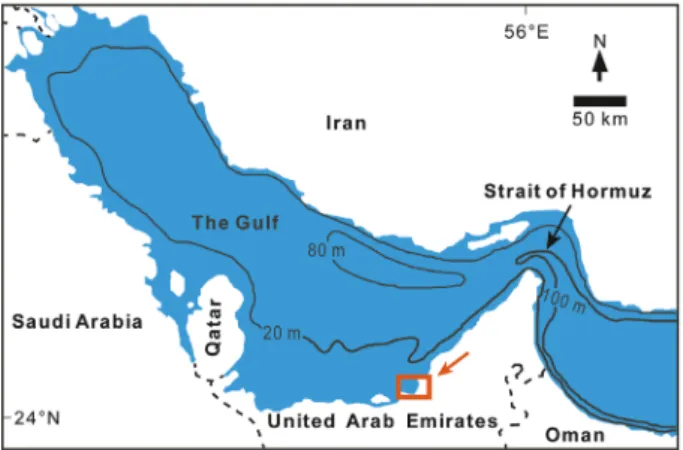
Fig. 1. Geographical location and bathymetry of the Gulf (modified from Sadrinasab & Kenarkohi, 2009).
The red box indicates the study area.
©2020 The Authors.Sedimentologypublished by John Wiley & Sons Ltd on behalf of
strong seasonal north-north-westerly winds (Shamals) (Fig. 2) frequently produce storm surges.
The evolution of modern Abu Dhabi nearshore topography is related to eustatic changes induced by Quaternary glaciation events (Evans et al., 1969; Stevens et al., 2014; Lokier et al., 2015). Glacioeustatic sea-level fall during the early and middle Pleistocene (>250 ka), resulted in the covering of the Abu Dhabi region by sili- ciclastic aeolian dunes (Ghayathi Formation;
Evans et al., 1969; Stevens et al., 2014). Subse- quent sea-level rise (ca 250 to 200 ka) resulted in a marine transgression and associated carbon- ate deposition. Renewed regression culminated in exposure and aeolian reworking of these car- bonates to produce a carbonate variant of the
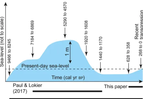
Ghayathi Formation. A major transgressive event at ca 125 ka (Marine Isotope Stage – MIS – 5.5) resulted in renewed flooding of the Gulf, and deposition of the overlying Fuwayrit Formation (Stevens et al., 2014). The last glaciation (ca 18 ka) resulted in a regional sea-level fall to ca110 to 130 m lower than present day sea-level (Whitehouse & Bradley, 2013). With the termina- tion of the glaciation, Holocene sea-level fluctua- tions produced a transgression from 7 to 5 ka, followed by a forced regression to present sea- level by 1440 to 1170BP (Lokier et al., 2015).
More recently, the relative sea-level in the Abu Dhabi lagoon is again rising, causing a transgres- sion with renewed flooding of the sabkha and a retrogradation of the lagoonal coastline (Lokier et al., 2018). Due to the very gentle slope of the
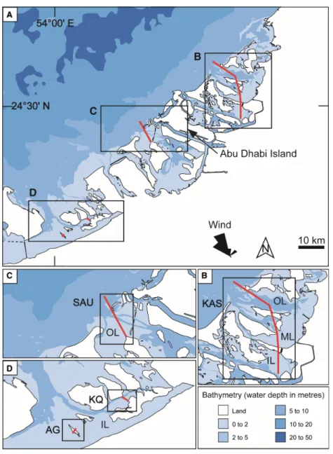
Fig. 2. Geographical location and bathymetry of the study area (sample transects are indicated by the red lines in black frames). (A) The relative location of the four studied transects along the Abu Dhabi coast. (B) The Khawr as Sadiyat (KAS) transect ranges from inner lagoon (IL), to middle (ML) and outer lagoon (OL). (C) The Shalil al Ud (SAU) transect includes outer lagoon (OL) and adjacent offshore environments. (D) The Al Gharbia (AG) and Khawr Qantur (KQ) transects both include only inner lagoon environments (IL). The bathymetry data was sourced from United Arab Emirates- Approaches to Abu Dhabi (Abu Zaby) (Marine Chart:
SA_GB45050B), and the wind data from El-Sayed (1999).
carbonate ramp, even a small change in relative sea-level will result in a considerable lateral dis- placement of the coastline.
MATERIALS AND METHODOLOGY
Fieldwork and sample collection
A grid of sampling locations was defined that covered the Abu Dhabi lagoon. Sites along tran- sects chosen for this paper were selected based on the presence of cemented intervals, accessi- bility and the degree of anthropogenic influence (Fig. 2). Refer to Table 1 and Figs 2 and 3 for the physiographic context of the studied tran- sects. Three sampling campaigns (November 2017, March 2018 and January 2019) were con- ducted along the Abu Dhabi nearshore and adjacent offshore environments to collect sedi- ment (hardgrounds, firmgrounds and unconsoli- dated sediment) and water (surface water and porewater) samples. In deeper water locations, sediment samples were collected using an Ekman grab sampler with a grab size of 15 915 cm. In the field, a hand-held Ultrame- terTM (Model 6P; Myron L Company, Carlsbad, CA, USA) and refractometer were used to mea- sure salinity, temperature, oxidation-reduction potential (ORP) and pH of water samples on site. Additional collected water samples were fil- tered with a 0.2 lm diameter filter into: a 2 ml plastic vial [for inductively-coupled plasma spec- trometry (ICP) analysis] and a 50 ml PVC tube (for alkalinity and for repository). Air bubbles were carefully expulsed from the water samples during sampling to reduce any exchange of gases.
Porewater samples were collected by inserting Rhizons (pore size of 0.12 to 0.18 lm) into the sediment profile (centimetres to some decime- tres), and then transferred to their respective vials using 0.2lm filters. In the field, all samples were kept cool to reduce microbial activity and subse- quently stored in a refrigerator prior to shipping to the Ruhr-University Bochum, Germany for pro- cessing.
Optical, cathodoluminescence and scanning electron microscope analyses
Thin section and scanning electron microscopy (SEM) were performed for the cemented and unconsolidated sediments to observe fabrics and mineral compositions at Ruhr-University
Bochum. The thin sections were dyed with Ali- zarin Red S and potassium ferricyanide (Fried- man, 1959; Dickson, 1965) to distinguish carbonate mineralogy and porosity. Photographs were taken using a Zeiss optical microscope (Zeiss, Oberkochen, Germany). Freshly broken samples were washed with deionized water and coated with gold prior to SEM observation (Zeiss-Gemini 2-Merlin HR-FESEM). The SEM parameters included an acceleration voltage from 0.2 to 30 kV, a resolution of 0.8 nm at 15 kV and 1.4 nm at 1 kV. In conjunction with SEM, energy dispersive spectroscopy (EDS) was conducted for element analysis of different cement phases, specifically to separate aragonite (Mg below detection limit), calcite (ca 2 wt.%
Mg) and gypsum cements. The cathodolumines- cence microscopy facility at Ruhr-University Bochum offers access to a ‘hot cathode’ micro- scope (type HC1-LM; lumic, Dortmund, Ger- many). The acceleration voltage of the electron beam is 14 kV and the beam current is set to a level to produce a current density of ca 9 mA mm2on the sample surface.
Geochemical analyses of water and sediment samples
Water samples were measured for alkalinity and elements at Ruhr-University Bochum. For alka- linity analysis, three drops of indicator solution (HCl) were added to a 5 ml sample. Following mixing, the solution was titrated with titration solution (HCl). Alkalinity was then calculated based on the volume of titration solution needed to produce the colour change of the solution (from blue to red). Elemental concentrations (Mg, Ca, Sr, Fe and Mn) of water samples, were measured on an inductively-coupled plasma – optical emission spectrometer (ICP–OES;
Thermo iCAP 6000 Series; Thermo Fisher Scien- tific, Waltham, MA, USA) by mixing 1 ml sam- ple water with 1 ml milli-Q water and 1 ml 3 M HNO3. BCS-CRM 512 and 513 (dolomite and cal- cite) were used as standards.
Microprobe analysis was conducted using a Cameca SX Five FE (Cameca, Gennevilliers Cedex, France) equipped with five different spectrometers at the Ruhr-University Bochum.
Accelerating voltage was 15 kV and beam cur- rent 20 nA. Elemental maps were created for the following elements: aluminium (Al), calcium (Ca), magnesium (Mg), sodium (Na), silica (Si) and strontium (Sr).
©2020 The Authors.Sedimentologypublished by John Wiley & Sons Ltd on behalf of
Radiocarbon dating
Four cemented samples (two from the inner lagoon and two from the outer lagoon) from the Khawr as Sadiyat transect were 14C-radiocarbon dated. Between 14 mg and 100 mg of material was drilled from filter-feeding Brachidontes bivalve shells cemented within the hardground.
Shells were examined to rule out taphonomic processes that would bias radiocarbon analysis.
The drilled powders were analysed using accel- erator mass spectroscopy (AMS) by Beta Ana- lytic, Radiocarbon Dating Laboratory in London, UK. The conventional radiocarbon ages were calibrated against a marine calibration curve uti- lizing the CALIB calibration program (Stuiver &
Reimer, 1993) applying a regional reservoir age correction of 18053 (Hughenet al., 2004).
Raman spectroscopy
Raman spectroscopy was performed using a WITec alpha 300 R (WITec GmbH, Ulm, Germany) confocal Raman microscope (CRM) with a Zeiss LD Plan NEOFLUAR 209 lens at the Helmholtz Center for Polar and Marine Research at the Alfred Wegner Institute (addi- tional reading: Nehrke & Nouet, 2011; Nehrke et al., 2012; Wall & Nehrke, 2012). This method
provides a quantitative characterization of car- bonate mineralogies. Scans of a hardground thin section from the Khawr as Sadiyat transect were imaged using a motorized scan table. A total scan area of 700 9650lm was measured, with a resolution of 2 lm (resulting in a total of 113 750 single Raman spectra) and an integra- tion time of 0.1 s per Raman spectra. Excitation wavelength was 488 nm and the spectrometer an ultra-high throughput spectrometer (UHTS 300; WITec, Germany; grating 600/mm, 500 nm blaze) equipped with an electron multiplying CCD (EMCCD) camera. Data analysis was per- formed using the WITec Project FOUR 4.0 soft- ware.
Aragonite cement precipitation experiments Inorganic CaCO3 precipitation experiments were conducted at Graz University of Technology (Austria) in order to assess the significance of solution chemistry on mineral morphology and surface structure during aragonite growth. The detailed description of the experimental set-up has been reported by Goetschl et al. (2019).
Briefly, the precipitation of aragonite at ambient temperature was induced by the addition of two inlet solutions in a mixed-flow reactor contain- ing CaCO3seed material. The two inlet solutions
Transect Start point End point Environments studied
Al Gharbia (AG) 24°8.4880N, 54°0.9320E
24°8.6640N, 54°1.2030E
Intertidal sabkha and inner lagoon
Khawr Qantur (KQ) 24°9.7230N, 54°8.0000E
24°10.9920N, 54°6.1710E
Intertidal sabkha and inner lagoon
Shalil al Ud (SAU) 24°23.5750N, 54°17.3250E
24°27.4120N, 54°14.4290E
Outer lagoon and adjacent offshore area
Khawr as Sadiyat (KAS)
24°27.6070N, 54°34.1540E
24°37.9850N, 54°28.3340E
Inner, middle, outer lagoon and adjacent offshore area
Fig. 3. Schematic cross-section of the Abu Dhabi nearshore area. Further details of each subzone are shown in the indi- cated figures. (Note: The horizontal direction is without scale; colours indicate water depth as referenced in Fig. 1.)
contained (Ca, Mg)Cl2 and Na2(CO3, SO4), respectively, and were pumped via a peristaltic pump in the reactor at a constant flow rate ofca 10 ml day1. The initial 05 L solution in the reactor contained 10 mM both CaCl2 and MgCl2, as well as varying concentrations of Na2SO4. Ionic strength of all solutions remained con- stant at 400 mM during each experimental run by adding NaCl if necessary. The pH was kept constant at 6301 by continuous bubbling of CO2 gas into the reactive solution. An aliquot of the reactive solution was collected every 24 h with a syringe for chemical analyses, so that the volume of the reactor solution remained near constant (within 4%). Directly after sampling, the collected solution was filtered through using a 0.2lm membrane cellulose acetate syringe filter and the pH was measured with a calibrated pH electrode cou- pled to a meter using a three-point calibration.
After a total experimental duration of 12 days, the solid material was collected using a suction filtration unit, rinsed with ultrapure deionized water, and dried.
RESULTS
Depositional environments and facies distribution
Based on the degree of isolation from the Gulf due to the presence of shoals and barrier islands, the nearshore area described here is broadly sub- divided into four physiographic settings (Fig. 3).
The terminology applied (outer, middle and inner lagoon, and intertidal sabkha) is, at best, a very coarse approximation, as water depth, level of restriction and hydrodynamics change both perpendicular and parallel to the coastline, resulting in a complex, highly dynamic system.
The intertidal sabkha is studied at Al Gharbia (AG) and Khawr Qantur (KQ), the inner lagoon at Al Gharbia, Khawr Qantur and Khawr as Sadiyat (KAS), the middle lagoon at Khawr as Sadiyat and the outer lagoon at Khawr as Sadiyat and Shalil al Ud (SAU; Table 1). Please refer to Tables 2 and 3 and Figs 4 to 10 for an overview of depositional environments, bathymetry, char- acteristic features, sediment composition, hydro- dynamic level and a systematic overview of the sedimentary and morphological characteristics of different types of cemented intervals described herein. Moreover, samples were collected from man-made exposures of Pleistocene cemented
intervals resulting from channel-building pro- jects. These are located a few kilometres south- east of the southern extension of the KQ transect.
Macroscopic and sedimentological properties of cemented intervals
Intertidal sabkha
Firmgrounds at the surface of the intertidal sab- kha at KQ occur as lithified carbonate units with a black-stained, irregular, mammillated upper surface microtopography (Table 3; Fig. 7A).
These firmgrounds are laterally discontinuous, often as isolated patches (predominantly 0.4 to 1.0 m in size) separated by pervasively-biotur- bated unconsolidated sediment. The lower sur- faces of these firmgrounds are irregular and display numerous hollows 1 to 5 cm in diameter (Fig. 7A). The amount of cementation decreases downward within the firmground, passing into completely unlithified sediment at a depth of 3 to 6 cm. No boring or biotic encrustation is observed. Landward, at AG (Fig. 2D), these firm- grounds are broken up and reworked to produce clasts some centimetres to some decimetres in diameter (Fig. 6A). The firmgrounds are locally covered by a thin sediment veneer washed onto the cemented intervals by wave and current activity.
Inner and middle lagoon
In the inner and middle lagoon, seafloor lithifi- cation is widespread and variable (Table 3).
Fully-lithified hardgrounds are exposed at the seafloor, and locally covered by coarse bioclastic sediment, (pel)ooidal sands, or carbonate silt and mud. Locally-developed thin, friable crusts are covered by some tens of centimetres of car- bonate mud, silt and sand. In the inner lagoon of KQ (Fig. 2D), bordering the intertidal sabkha, three distinct hardground layers (top layer, 1.0 to 1.5 cm thick; middle layer, 1 to 2 cm; bottom layer, 1 to 3 cm) are vertically separated by unconsolidated sediment (2 to 4 cm; Fig. 6B).
These ‘stacked’ hardgrounds exhibit a down-sec- tion increase in cementation and a change in colour from white to grey. The top hardground is either exposed or locally covered by ca 2 cm of sediment. The upper surfaces of the hard- grounds are flat with rare borings (<1 to 3 mm), and the lower surfaces are irregular.
At the high energy setting of AG (Fig. 2D), the cemented intervals are exposed at the seafloor (Fig. 4C) or locally covered by about 10 to 50 cm unconsolidated sediment (generally
©2020 The Authors.Sedimentologypublished by John Wiley & Sons Ltd on behalf of
Table2.Depositionalenvironmentsandfaciesdistribution.RefertoFigs2and3forkeytotransects,andFigs4to6formoredetails. PhysiographyBathymetryMainfeaturesSedimentcompositionHydrodynamicenergy Intertidal sabkha0–0.5m 0.2–0.4min tidalcreeks Microbialmatswithlargepolygon structure(upto1mindiameter)KQ:peloids(60–80%),withsiltandclay(20– 40%). AG:sand-gradegrains(80–90%)consistingof peloids(40–80%),gastropods(6–40%), foraminifera(3–15%)andquartzgrains(0–9%)
VerylowlevelalongtheKQ transect.Locallyhigherenergy (duetothelackofbarrier islands)alongtheAGtransect InnerlagoonExposedat lowtide, <2mathigh tide
Waveandcurrentripplesareabundant inareasdevoidofseagrass.Inthe middleportionsoftheKAStransect,a networkofcentimetres-deeptoafew decimetres-deeptidalchannelsand lobateerosionalscoursarefound Sedimentdominatedbypeloids(30–90%), gastropods(1–30%),foraminifera(1–20%), bivalves(1–16%)andquartzgrains(1–15%). Narrownearshorebeltismadeupofwell-sorted carbonatesands.Skeletalandquartzgrains (<14%)areabundantininnerAGlagoon. Peloidsandaggregategrains(3–8%)are abundantatKQandKAS
Low,whenprotectedbybarrier islandstomoderatelyhigh undertheinfluenceofhigh, north-north-westerlywinds (Shamals).Wave-baseand seafloorinteractioncanstirup sediment Middle lagoonLocally exposedat lowtide, <3mathigh tide
Middlelagoonlieswithintheinner islandcomplexbetweentheformertwo environments.Locally,thebarren seaflooriscomposedofhardgroundsin partcoveredbythinveneerofshell debris.Largepolygonalsystemsof cracks(mega-polygons)areexposed duringlowtide KAS:Unconsolidatedsedimentiscolonizedby mangrovesandseagrass.Seaward,peloids (50%),gastropods(20%)andforaminifera(15%) dominatesediment(bioclasts<5cmindiameter tomudgrade).Areniticcarbonateincreasesin abundance(60–70%)landward.Quartzgrains(2 –3%)component,withcarbonatemud(1–6%) andsilt(14–43%)fractionsincreaselandward
Low,whenprotectedbybarrier islandstohighinopensettings andundertheinfluenceof high,north-north-westerly winds(Shamals).Wave-base andseafloorinteractioncan stirupandwinnowsediment Outerlagoon andoffshoreLocally exposed(ooid shoals)to <10mintidal channels
Incomparisontothelagoonal environments,whichareinfluencedby tidalinteractionsbetweenthesmall islands,theoffshorearearepresents open-waterconditionsdominatedby waveandcurrentaction.Inthebroad tidalchannels,theseafloormaybe sweptcleanorlocallycoveredby migratingsanddunes AtKASandSAU,tidalchannelswithooid shoalcomplexesthatterminatelandwardand seaward.Inter-shoalareasarecharacterizedby seagrasswithepiphyticbivalves,gastropodsand foraminifera.Ooids(60–90%),gastropods(4– 40%)andcalcareousalgae(2–40%)aremain composition.Grainsizeisvariable,withclay andsiltcomponentsreachingupto36%in inter-shoalareascoveredbyseagrass,andupto 88%coarsesandonshoals Lowondaysoflowwind strengthsbutdominatedby intensetidalcurrents.High duringhighwindevents. Strongwavebaseandcurrent interactionatooidalshoals
Table3.Sedimentaryandmorphologicalcharacteristicsofdifferenttypesofcementedintervals. TypeLocationEnvironment
Water depth (m)
Sediment cover (cm)Thickness (cm)Upper surfaceLower surfaceEvidenceof encrustationCementfabricmorphologyandmineralogy Actualistic firmgroundKhawr QanturIntertidal, lowenergy0.0–0.30–13–6IrregularIrregular with hollows
NoneLath,platy,columnarandprismatic aragonite.Someroundvoidsat terminationsofprismaticaragonite.High- Mgcalcitemicrite Concretionary (sub) hardground
Khawr as Sadiyat
Inner lagoon,low energy
0.0–1.015–208–20PlanarIrregularNoneLath,platy,columnarandprismatic aragonite.Commonroundvoidsat terminationsofprismaticaragonite.High- Mgcalcitemicrite Inner-lagoon hardground gradinginto beachrock
Al GharbiaInner lagoon,high energy 0.0–0.60–5012–20to <1 landward PlanarIrregularOnly commonon thelower surface
Lath,platy,columnar,prismatic,fibrous andaciculararagonite.Rareroundvoidsat terminationsofprismaticaragonite.High- Mgcalcitemicrite Lagoon hardground witheroded tepees
Khawr as Sadiyat
Middleto outer lagoon, medium energy
0.5–2.00–25–15PlanarIrregularNoneLath,platy,columnar,prismatic,fibrous andaciculararagonite.Commonround voidsatterminationsofprismatic aragonite.High-Mgcalcitemicrite. Polygonalgypsum Lithified decapod burrows
Khawr as Sadiyat
Outer lagoon,high energy 1.0–5.0>53–15IrregularIrregularCommonon allsurfacesAciculararagonite
©2020 The Authors.Sedimentologypublished by John Wiley & Sons Ltd on behalf of
seaward; Fig. 7B). The black upper surfaces of the hardgrounds are flat with protruding skeletal fragments, and the lower surfaces are irregular.
These hardgrounds are up to 20 cm thick, but display a downsection and landward decrease of cementation, qualifying as firmgrounds at best (Figs 6A and 8E). Borings are not common, and encrustation by bivalves is ubiquitous on lower surfaces of exposed portions of the hardground (Fig. 8C).
In the middle to inner KAS lagoon (Fig. 2B), hardgrounds also range in thickness, continuity and degree of cementation. Fully-lithified suc- cessions up to 50 cm thick, of variably cemented sediment (Fig. 9C) occur near dredged channels at water depths of 1 to 2 m (Table 3; Fig. 9).
Hardgrounds of a few centimetres in thickness, brittle firmgrounds covered by 2 to 50 cm of unconsolidated sediment and marine plants occur in the most proximal settings. Both exposed and sediment-covered hardgrounds show conspicuously flat upper surfaces and a downward decrease in cementation. Where areas of the seafloor are locally denuded and exposed, centimetre-wide fissures form metre-sized poly- gons in the hardground (Fig. 9). The fissures are commonly filled by coarse bioclastic material and other sand-sized carbonates (Fig. 9D).
Outer lagoon
Two types of lithification are present in the outer KAS lagoon (Table 3). Fully-lithified hard- grounds form on the seafloor in high-energy
tidal channels at water depths of about 10 m and sand waves migrate across the otherwise barren seafloor. These features are not described in detail here as the evidence is indirect, origi- nating from grab sampling. Here, the focus is on intershoal areas, where the seafloor is patchily covered by seagrass (Figs 6D and 10) and cemented intervals are either exposed or covered by a thin and constantly moving sediment veneer (Fig 10). Hardground intervals occur as cemented decapod burrow networks and irregu- lar to patchy tabular nodules (some tens of cen- timetres in diameter); perhaps representing an amalgamation of several closely-spaced burrows (Fig. 10). In many locations, up to ca80% of the sediment consists of the friable to hard carbon- ate burrows. Individual cemented burrows have a very irregular morphology, typically some cen- timetres in diameter and extend over many tens of centimetres (Fig. 10). Rare bivalves and barna- cles encrust the upper surface of the hard- ground, while serpulid encrustation is ubiquitous.
Cemented intervals: radiocarbon ages, mineralogy and cement fabrics
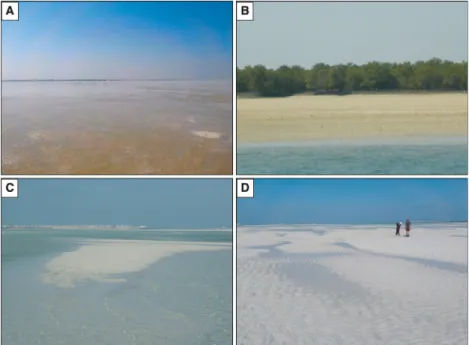
An overview of previously published radiocar- bon ages and new data obtained in the context of this study are shown in Fig. 11. Here, Brachi- dontes bivalve shell fragments (avoiding endo- lithic shells) encased in the cemented intervals from the inner KAS lagoon yield 14C ages Fig. 4. Field images from the
intertidal sabkha and inner lagoon.
(A) Intertidal sabkha microbial mats at Khawr Qantur (KQ) showing well-developed polygon structures.
(B) Seaward edge of the microbial mats at the KQ intertidal sabkha, showing patchy distribution (black arrow) separated by unconsolidated sediment. (C) Lithified fractured hardground of the Al Gharbia (AG) inner lagoon covered by shallow water. (D) An exposed shoal from the Khawr as Sadiyat (KAS) inner lagoon, with localized algae (black arrow) growing on bioclasts. Image taken at low tide.
between 268 cal yrBP and 0 cal yr BP. This Recent age for the bivalves proves actualistic hardground formation within the inner lagoon.
Radiocarbon ages of 628 to 422 cal yrBP and 608 to 358 cal yrBP are determined from bivalves in cemented intervals of the outer lagoon ooid shoal belt.
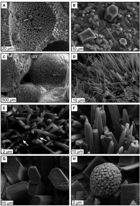
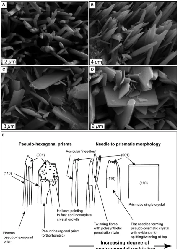
The cemented intervals (Table 3) contain arago- nite cements (Figs 12 and 13) with a wide spec- trum of morphologies and locally abundant
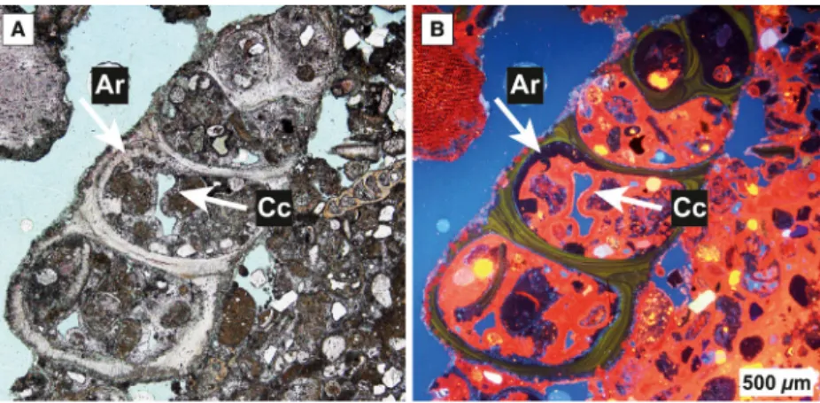
micritic (calcitic; Figs 12A and 13) and gypsum cements (Fig. 12B). Elemental analyses (EDS and microprobe), and particularly mineralogy data (Raman spectroscopy; Fig. 14) and crystal mor- phologies, collectively conclude acicular, fibrous, elongate prismatic, lath and platy cements to be aragonitic, and marine in origin (Fig. 12). High- Mg calcite cements display orange, while arago- nite cements are characterized by dark red to purple luminescence (Fig. 13).
Fig. 5. Field photographs from the middle and outer lagoon. (A) Extremely shallow water with localized exposure at the Khawr as Sadiyat (KAS) middle lagoon during low tide. The width of the image in the foreground isca5 m. (B) Localized mangroves in the KAS middle lagoon. The mangroves are ca3 m high. (C) Exposed ooid shoal during low tide at the KAS outer lagoon. The width of the image in the foreground isca6 m. (D) Wave ripples and tidal creeks on the crest of a Shalil al Ud (SAU) outer lagoon ooid shoal (persons to the right are ca1.8 m tall).
Fig. 6. Seafloor features from the intertidal to outer lagoon. (A) Firmgrounds break into centimetre to decimetre scale intraclasts (tape measure for scale isca20 cm in length) in the Al Gharbia (AG) intertidal zone. (B) Lithified interval from the Khawr Qantur (KQ) inner lagoon. Thin sediment cover has been removed by hand. (C) Abundant bioclasts and unconsolidated sediment in the Khawr as Sadiyat (KAS) middle lagoon (hammer head isca15 cm in length for scale). (D) Seagrass with unconsolidated ooids and bioclasts from the KAS outer lagoon. Note the strong current originating from left of image.
©2020 The Authors.Sedimentologypublished by John Wiley & Sons Ltd on behalf of
Acicular cements present as needle crystals (Sandberg, 1985) dominate the cemented inter- vals in the outer lagoon adjacent to the offshore environment (Table 3; Fig. 12D). Acicular cements with pointed terminations are oriented perpendicular to grain surfaces and occur as isopachous fringes around bioclasts, peloids or ooids (Figs 12 and 15). In order to avoid confu- sion, crystal dimensions (or ranges thereof) will be presented in terms of length (L): width (W):
thickness (T) ratios. L:W:T ratios of acicular cements are 10–40:1–2:1–2 lm.
Morphologically, fibrous cements (Fig. 12E) are among the dominant fabrics in the cemented intervals of the outer and (partially) middle lagoon. Fibrous cements have flattened rather than pointed terminations and grade into crys- tals that are columnar in shape. The orientation of the fibrous cements is perpendicular and in places random relative to grain surfaces, particu- larly where the surface morphology is very irreg- ular due to microendolithic borings (Fig. 12E and F). Fibrous crystals have L:W:T ratios of 10–
20:1:1 lm.
Elongate prismatic (pseudo-hexagonal) cements show intergrowth with lath and platy cements in the intertidal sabkha and inner lagoon (Fig. 12G). The elongate prismatic cements have flattened terminations and well-defined crystal surfaces. The cements project outward from grain surfaces at random orientations. Elongate pris- matic crystals have L:W:T ratios of 10–25:5–12:2–
3 lm. Round voids frequently occur at the
outward crystal terminations (Fig. 12G). Elongate prismatic, lath and platy cements are often associ- ated with numerous framboids reaching 10 lm in diameter (Fig. 12H).
Cemented intervals in the intertidal sabkha and inner lagoon contain aragonite with a com- plex morphological succession, with fabrics ranging from needle-like to fibrous cements that grade into arrays of bifurcating fibrous cements, lath-cements and, finally, platy morphotypes (Figs 12 and 15). These cements project outward from grain surfaces at random angles (Fig. 15C and D). In the inner KQ and KAS lagoons, the L:W:T ratios are 4–10:3–6:2–4 lm in width. In the AG inner lagoon, L:W:T ratios are 2–8:1–2:1–
2 lm.
Microcrystalline and micritic cements (Mar- shall & Davies, 1981) occur as micron-sized (1 to 4 lm long), often curved-rhombic high-Mg calcite crystals with about 2 wt.% Mg (Figs 12A and 13).
This common form of submarine cement is likely generated by direct chemical precipitation and should not be confused with detrital micrite, which may result from the disaggregation of car- bonates and other processes, such as the forma- tion of destructive micritic envelopes. In some cases, micritic cements form the substratum of the above-mentioned acicular cements. These cements either coat grain surfaces as thin rims or accumulate as micro-peloids. Often, micritic cements overgrow calcitic substrata (for example, calcitic foraminifera tests; Fig. 12A), as well as aragonitic gastropods (Fig. 13). This cement
Fig. 7. Macroscopic variation of cemented intervals. (A) Khawr Qantur (KQ) intertidal sabkha firmground with irregular surface, consisting of microbial cover and underlying lithified sediment with vuggy porosity. (B) Al Gharbia (AG) inner lagoon hardground with irregular lower surface. Components include coarse bioclastic sediment.
(C) Near-planar lithified interval encrusted by algae and molluscs from the Khawr as Sadiyat (KAS) inner lagoon. (D) Outer KAS lagoon hardground with irregular and nodular surfaces, containing bivalve encrustation and borings.
phase is very abundant, but the abundances show significant lateral variability over distances of some metres only, in some hardground samples in the middle lagoon. In places, micritic cements may form up to 50% of the hardground cement phase (Fig. 13). Authigenic gypsum crystals are present as stubby to elongate prismatic cements in well-developed hardgrounds of the middle lagoon (Fig. 12B).
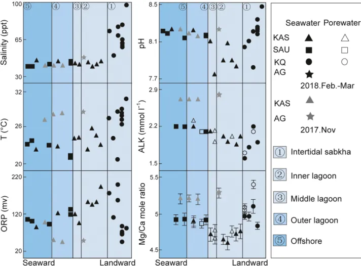
Spatial trends in seawater and porewater properties
Seawater and porewater properties were obtained during the first two field periods.
Between the two periods, seawater properties are relatively consistent in salinity and pH. In contrast temperature, oxidation-reduction poten- tial (ORP), alkalinity and elemental concentra- tions are all variable between November 2017 and February to March 2018 (Fig. 16). Compar- isons between seawater and shallow, oxidized porewater samples suggest that alkalinity and elemental concentrations of both fluid types are indistinguishable within error (Fig. 16). Salinity values show a decreasing trend seaward. Gener- ally, the most significant difference of salinity is between the intertidal sabkha and inner lagoon, whereas salinity remains relatively stable from the inner lagoon to offshore areas. Temperature Fig. 8. Spatial variation of
cemented intervals along the Al Gharbia (AG) transect. (A) The boundary (white stippled line) between the relatively shallow lithified seafloor and the deeper uncemented seafloor (persons of about 1.7 m height for scale). (B) The upper surface of shallower- water cemented intervals encrusted by biofilm and rare bivalves. (C) The lower surface of cemented intervals–landward but similar to (B) encrusted by abundant bivalves.
(D) The initial break-up of
cemented intervals from (B) and (C).
(E) Continued break-up of hardground intervals, resulting in centimetre to decimetre scale intraclasts near beach. (F) Intertidal, centimetre-thin, leather-like
beachrock. (G) A schematic figure of the cemented intervals along the transect with corresponding location of (A) to (F).
©2020 The Authors.Sedimentologypublished by John Wiley & Sons Ltd on behalf of
data show a similar trend but fluctuate between different times of the year. Higher seawater tem- peratures were recorded in November 2017 (av- erage= ca28°C,n = 4) compared to March 2018 (average = 24 to 25°C, n= 24). Alkalinity decreases from 2.2 to 1.6 mmol l1 within the intertidal sabkha and shows differences between the field periods (average = 2.72 mmol l1, n= 5, November 2017; average = 2.13 mmol l1, n= 27, March 2018) (Fig. 16).
No obvious differences of Mg/Ca molar ratios between seawater and shallow porewater sam- ples are observed but more detailed work and, specifically, monitoring are required. These ratios show higher values in November 2017.
Magnesium/calcium molar ratios, furthermore,
vary between environments, with the lowest val- ues in the inner lagoon (4.6 to 5.3), mid-range values in the outer lagoon to offshore area (4.8 to 5.3) and the highest values in the intertidal sabkha environment (>5.0; Fig. 16).
Aragonite precipitation experiments
X-ray diffraction (XRD) patterns of laboratory carbonate precipitates performed in the context of the study by Goetschlet al. (2019) are indica- tive for calcite and aragonite. The highest pro- portions of aragonite were precipitated in experiments conducted at fast mineral growth rates (growth rate> 107.2mol m2s1) and 30 mM sulphate concentration (similar to Fig. 9. Schematic of a landward to seaward profile of the development of hardgrounds, with the associated envi- ronmental factors in the Khawr as Sadiyat (KAS) middle to outer lagoon. (A) Illustration of landward–seaward changes in seafloor composition, hardground development, hydrodynamic level and mean grain size. (B) Outcrop of Pleistocene sedimentary rocks at shoreline. (C) Hardground from the submarine polygonal cracks. (D) Polygonal cracks in submarine hardgrounds filled with unconsolidated sediment. (E) The exposure of several stacked and amalgamated hardground intervals reaching 50 cm in thickness along the edge of a dredged channel.
seawater concentration) prevailing in the reac- tive solution. The SEM photographs of precipi- tates collected at the end of the experiments show elongated aragonite prisms with a pseudo- hexagonal shape. The observed porous surface structure of the (001) aragonite crystal surface resulted from experiments performed with Mg2+
and SO24bearing solutions.
INTERPRETATIONS AND DISCUSSION
Holocene sea-level change in the Gulf
Holocene sea-level rise led to rapid flooding of the Gulf sedimentary basin (Fig. 11) and the onset of widespread hardground formation throughout the open Gulf (average water depths of 35 m). Transgression reached the position of the current shoreline, and the position of the study area, by the Middle Holocene, briefly peakingca1 m above present day sea-level atca 4570 cal yrBP, before declining below current levels by 1440 to 1170 cal yrBP (Lokier et al., 2015) (Fig. 11). Radiocarbon ages indicate that
the lithification features described herein post- date the late Holocene regression (Fig. 11) and must be placed in the context of the more recent sea-level rise, leading to renewed flooding of the tectonically-stable, southern shore of the Gulf.
Five characteristic case examples of seafloor and sub-seafloor lithification are described, inter- preted and placed in the context of published work (see Table 3 for a systematic overview of the different types of cemented intervals).
Cemented intervals
The extremely low gradient (0.07 to 0.08°) of the Abu Dhabi carbonate ramp system results in sig- nificant seaward–landward displacement of the coastline and of facies belts even with small changes in sea-level. This is exemplified in the significant shifts (>2 km) of the waterline across a single tidal cycle (mean amplitude of ca 1.5 m). On the basis of field observations and radiocarbon dating of cemented intervals, the cementation features described here are geologi- cally very young and processes are active to the present day. The zone of active lithification Fig. 10. Cemented intervals from
the ooid shoal environment. (A) Shallow water depth and seagrass colonization (dark areas). The width of the image in the foreground isca 7 m. (B) Subaqueous concretionary cemented decapod burrow network interval. Note the holes formed due to unconsolidated sediment removed by currents. (C) The upper surface of an encrusted, ooid shoal- associated cemented interval. (D) The typical irregular morphology of a lithified decapod burrow. (E) Schematic of hardground
occurrence in the ooid shoal setting.
Grey colour refers to cemented burrow network.
©2020 The Authors.Sedimentologypublished by John Wiley & Sons Ltd on behalf of
migrates landward during the currently rising sea level, but lithification may be active at the seafloor or some centimetres beneath the seafloor at the redox boundary. In the terminology of sequence stratigraphy, the firmgrounds to hard- grounds described here qualify as lithified trans- gressive lag deposits, or as high order
‘parasequence boundaries’ (in the sense of Catu- neanu et al., 2009; “. . .relative conformable suc- cessions of genetically related beds or bedsets bounded by a flooding surface. . .”). Where pre- sent, the facies across the parasequence bound- ary change from the coarser-grained lithified (packstone to rudstone) facies beneath to the unconsolidated silt-sized carbonate sediments above. In many places, however, the sediment on top of the actualistic (flooding) parasequence boundary has not yet been deposited. The early diagenetic cementation features in the Abu Dhabi coastal sabkha and lagoons are highly diverse. In the view of the authors, the wide spectrum of (sub)recent lithification features documented within the relatively small study area have no (preserved) analogue in the rock record. Below, five characteristic settings with cemented intervals are described and interpreted in the context of data compiled by the authors and previous workers.
Actualistic firmgrounds in the intertidal Khawr Qantur coastal sabkha
In the context of a Late Holocene regression that post-dates the relative highstand (5290 to 4570 cal yrBP; Fig. 11; Lokier et al., 2015),
diachronous firmgrounds to hardgrounds form in the Khawr Qantur (KQ) intertidal sabkha (Table 3; Fig. 2D). These features were described in detail in Paul & Lokier (2017) and were interpreted as forced regression hardgrounds, overlying an older, transgressive hardground (7184 to 6869 cal yr BP). Radiocarbon ages of a gastropod from the seaward hardground site described in Paul & Lokier (2017) give a cali- brated age of 0 to 256 cal yr BP(Lokier & Steuber, 2009). Complexity arises from the fact that these hardgrounds are diachronous (lithoclines sensu Purser, 1969) and one stage amalgamates with the following stage in either a seaward or land- ward direction.
Actualistic firmgrounds are brittle lithified crusts that form under the influence of rising relative sea level, stepping landward over sab- kha sediments. Towards the upper limit of the intertidal zone, these firmgrounds thin and show patchy cementation suggesting that these are the most recent and incomplete stages of lithifica- tion. Seaward, the firmgrounds thicken, with increasing degrees of cementation, and are bur- ied beneath thin layers of sediment.
Morphologically conspicuous, lath-shaped as well as columnar aragonite cements induce the lithification of peloidal sediments (Fig. 15).
Often, individual crystals are covered by mucilaginous films, suggesting a link between microbial metabolism and early diagenetic lithifi- cation. Actualistic firmground cements described here differ from Middle to Late Holocene cemen- ted intervals from the same transect, which
Fig. 11. Compilation of the dated cemented intervals from various studies (Shinn, 1969; Paul & Lokier, 2017; this study), and their relation to sea-level changes in the area. The sea-level curve is modified from Paul & Lokier (2017).
contain a more diverse mineralogy, including aci- cular aragonites, dog-tooth high Mg-calcites, as well as (non-stoichiometric) dolomite rhombohe- dra (Paul & Lokier, 2017). It seems likely that the observed differences in cement parageneses describe an evolution of hardground cementation over time, with the initial stage documented here (KQ transect in Fig. 2D) and more advanced stages described in Paul & Lokier (2017).
The KQ case examples document the highly complex firmground to hardground dynamics in a sabkha intertidal setting exposed to high-fre- quency, low-amplitude sea-level change. The result is a diachronous pattern of lithified
surfaces that may amalgamate both seaward and landward. Supersaturated seawater with respect to aragonite, tide-induced water circulation, evaporation during low tide and microbial activ- ity induce precipitation of aragonite cements and subordinate calcite and gypsum cements.
The characteristically mammillated and irregular upper surfaces of the brittle firmgrounds devel- oped in this environment are indicative of low hydrodynamic level. It is acknowledged that the level of research presented here, and in previous papers, is insufficient to capture the complexity of firmground in the intertidal sabkha of Abu Dhabi. Previous work dealing with microbe–
Fig. 12. Scanning electron
microscope (SEM) images of various cement types from the Abu Dhabi lagoon and intertidal sabkha. (A) Micritic and rhombic high-Mg calcite cements within a bioclast chamber from the Khawr as Sadiyat (KAS) middle lagoon. (B) Polygonal gypsum cements covering a grain surface from the KAS middle lagoon. (C) Acicular aragonitic cement covering oolitic and peloidal sediment from the KAS outer lagoon. Note the microbial filaments. (D) Acicular (needle) aragonitic cements from the high- energy settings of the Al Gharbia (AG) inner lagoon. (E) Outer KAS lagoon fibrous aragonitic cements, with associated microbial filaments (arrowed). (F) Fibrous aragonitic cements with small holes at the termination, Khawr Qantur (KQ) inner lagoon. (G) KAS inner lagoon cements showing elongated prismatic aragonite cements with voids at the (001) (termination) surface. (H) Platy aragonitic cements associated with framboids in the KAS inner lagoon.
©2020 The Authors.Sedimentologypublished by John Wiley & Sons Ltd on behalf of
sediment interaction in this area has mainly focused on the formation of highest Mg-calcite and non-stoichiometric dolomite in sabkha
sediment (e.g. Bontognali et al., 2010). In con- trast, the role of biofilms on firmground arago- nite and micritic Mg calcite cement nucleation and precipitation in the intertidal sabkha is underexplored. These features call for a study combining geomicrobiological, sedimentological and carbonate geochemical expertise.
Concretionary (sub)hardgrounds in the Khawr as Sadiyat inner lagoon
Shallow lagoonal cemented intervals in the innermost portion of the Khawr as Sadiyat (KAS) transect (Table 3; Fig. 2B) have been 14C dated to 268 to 0 cal kyr BP to Recent. Encrusta- tion or borings by endolithic organisms such as serpulids, bivalves or sponges (Fig. 7C), a fea- ture typical for many of the firmgrounds to hard- grounds elsewhere in the Abu Dhabi lagoon, are lacking. In the literature, the absence of hard- ground encrustation and of endolithic borings are often taken as evidence of very short hiatal durations (Kennedy & Garrison, 1975). The case example documented here attests to the com- plexity of these processes. These brittle layers are overlain by some centimetres of fine-grained sediment and millimetre-thick microbial layers at the seafloor. No evidence is found that these features, characterized by conspicuously planar upper surfaces, represent conventional lithified seafloors subsequently buried under a shallow sediment cover.
A further conspicuous feature of these layers is the platy to columnar morphology of the Fig. 13. Thin section images (plane polarized light) from Khawr as Sadiyat (KAS) middle lagoon. (A) Gastropod encased in firmground. Note aragonite (fibrous, Ar) and calcite (micritic, Cc) cements coating the shell interior and encasing sediment. (B) As (A) but under cathodoluminescence. Note green luminescence colour of gastropod shell, purple to dark red (Ar) cement fringes and bright orange micritic cement. In this specific sample, micrite cement forms up to 50% of all early marine cement phases. Micrite cement rests on shell material, aragonite cements and sediment. Remarkably, less than 10 ppm Mn2+in the crystal lattice of calcitic sediments and cement are sufficient to induce bright orange luminescence in these actualistic sediments and cements.
Fig. 14. Raman microscopy scan of a hardground from the Khawr as Sadiyat (KAS) inner lagoon docu- menting the aragonitic nature of the bulk of hard- ground cements. Aragonite is indicated by the blue colour, porosity is indicated by black and quartz is indicated by red. Primarily, round grains are com- posed of aragonite, with the exception of the quartz at the bottom left. White dashed lines indicate the grain boundaries, whereas yellow dashed lines indicate the edge of the fringing aragonitic cements.
Fig. 15. Aragonitic cement morphologies from the Khawr as Sadiyat (KAS) lagoon. (A) Acicular cements in the outer lagoon. (B) Acicular cements showing twinning from the outer lagoon [but landward of (A)]. (C) Platy cements with pseudo-prismatic terminations from the inner lagoon. (D) Well-defined platy cements in the inner lagoon. (E) Sketch illustrating various cement fabrics as shown in SEM photographs (A) to (D). Trend from elon- gated pseudo-hexagonal fibers to prisms shown to the left. Trend from needle and fibrous to platy cements shown to the right. Degree of environmental restriction increases to the right. Note that the complexity of parameters that induce these morphological changes are not yet well understood.
©2020 The Authors.Sedimentologypublished by John Wiley & Sons Ltd on behalf of
aragonite cements. Rarely described in the lit- erature, these cements lithify the carbonate sands (Figs 12 and 15). Numerous pyrite fram- boids (i.e. spherical aggregates of FeS2 micro- crystallites; Rickard, 1970) are embedded between these crystals (Fig. 12H). Several papers have discussed the level of complexity surrounding framboid formation and diagenesis (Sawlowicz, 1993; Wilkin & Barnes, 1997).
Nevertheless: (i) the small size of the fram- boids (5 to 10lm) suggests H2S-bearing, oxy- gen-depleted pore waters (Wignall & Newton, 1998); and (ii) the presence of microbial com- munities in the inner lagoon provides a supply of abundant organic matter and may indicate a relation between microbial metabolisms and framboid formation.
Judging from field observations, the porewa- ter redox boundary, situated about 15 to 20 cm beneath the seafloor (Fig. 6B), defines the
upper limit of concretionary layers and may explain the uncommonly planar upper surface of these features. Interestingly, Pleistocene counterparts of the Khawr as Sadiyat inner lagoon (sub)hardgrounds are exposed due to channel construction work a few kilometres landward of the KQ transect. These display very similar, albeit fossil, examples of these concretionary sub-hardgrounds (Fig. 17).
With reference to the actualistic lithified inter- vals, cementation within the sediment column is possibly due to bacterial sulphate reduction (BSR; Berner, 1981). In this process, bicarbonate (HCO3) is produced and, when deprotonated, it forms CO32-. Given the abundance of Ca, an increase of alkalinity and porewater supersatura- tion with respect to CaCO3 result, and the sul- phate inhibitor is removed. The following generalized equation (see discussion in Petrash et al., 2017) describes this process:
Fig. 16. Surface seawater and porewater properties along studied transects: ALK, alkalinity; ORP, oxidation- reduction potential.
CH3COOþSO24þH2O!H2Sþ2HCO3 þOH As a consequence, beneath the redox boundary aragonite and high-Mg calcite cementation from pore fluids with high Mg:Ca ratio take place.
Under the hot arid climate in the Gulf, the surfi- cial porewater is evaporated during low tide exposure of the inner lagoonal carbonate sea- floor, inducing additional oversaturation (Noble
& Howells, 1974) with respect to carbonate.
Moreover, oxidation of organic matter in the uppermost oxic sediment column generates CO2, which in turn, causes the pH to decrease and porewater may become undersaturated with respect to more soluble carbonates such as arago- nite (see discussion in Swart, 2015). With respect to ubiquitous aragonite cement precipitation beneath the redox boundary, the following con- siderations are relevant: the formation of early diagenetic concretionary nodules in the upper sediment column has been reported from numer- ous Holocene and older case examples (see Mul- lins et al., 1980, for a discussion of Holocene carbonate nodules). Dissolution of (primarily)
aragonite occurs within the oxic zone of surficial sediment by oxidation of organic matter. Cement precipitation in the pore space within the upper sediment column results from the mixing of dif- ferent hydro-chemical zones including the iron- reducing zone, downward diffusion of Ca2+ and bicarbonate, and increased alkalinity due to hydrogen consumption by iron reduction (Coim- bra et al., 2009). All of these factors are in agree- ment with the working hypothesis proposed here.
Moreover, the high Mg:Ca pore fluid ratios may inhibit high-Mg calcites to pass the nucleation boundary and thus explain the dominance of aragonite cements (Morseet al., 1997).
Geochemical fingerprints for either BSR or dee- per-seated methanogenesis (Berner, 1981) are often found in characteristic d13C values (Games et al., 1978). Given that the aragonitic cements are a volumetrically minor component of bulk samples, isotope data compiled so far plot within the range of published marine carbon isotope data (2.6 to 4.3&; Paul & Lokier, 2017) in the Abu Dhabi lagoon. The way forward is to apply spa- tially-resolved secondary ion mass spectrometry Fig. 17. Pleistocene hardground exposures due to channel-building activity to the south-east of the Khawr Qantur (KQ) transect. In the view of the authors, these features represent fossil representatives of the inner lagoon concre- tionary sub-hardgrounds (Fig. 7C). (A) Section of concretionary planar sub-hardground covered by ca 15 cm of poorly lithified sediment. Finger is 2 cm wide. (B) Sub-hardground surface exposed along channel. Note the extre- mely planar upper surface. Hammer for scale, 30 cm long. (C) Close up of (B). Serpulid to lower left is not encrusting but a component of the lithified interval. Finger is 2 cm wide. (D) Scanning electron microscope (SEM) image of cement phase lithifying Pleistocene sub-hardgrounds. Two cement phases are visible: (i) a corroded cal- cite phase; replaced by (ii) newly forming calcite rhombohedra. It seems likely that these calcites formed as a result of meteoric diagenesis and calcite to aragonite transformation.
©2020 The Authors.Sedimentologypublished by John Wiley & Sons Ltd on behalf of
intervals. This is work in progress.
These processes discussed here are not suffi- ciently understood and must be the topic of spa- tially-resolved geochemical analysis, detailed porewater sampling and analysis spreading over one to several years combined with field moni- toring experiments. This is work presently underway. Assuming that the above model is correct, the question arises of whether these cemented intervals qualify as genuine firm- grounds to hardgrounds or if they share more similarities with concretionary layers? It is pro- posed that this type of cemented interval should be referred to as ‘concretionary sub-hard- grounds’ because they are not previously described in the literature. Concretionary sub- hardgrounds are relevant as they may contribute to the discussion on the origin of some of the rhythmical shallow water limestone–marl alter- nations as discussed in Munnecke et al. (2001).
Conventionally, these successions are assumed to record cyclic sedimentation linked to Milan- kovitch cycles. Data shown here, i.e. the early marine diagenetic formation of concretionary sub-hardgrounds, might be relevant in this con- text as here a process is at work that is appar- ently not related to orbital cycles. Moreover, concretionary sub-hardgrounds may eventually become exposed at the seafloor due to winnow- ing and removal of the overlying sediment. In the fossil record, exhumed concretionary sub- hardgrounds are then easily confused with genuine marine hardgrounds. An important difference is that exposed sub-hardgrounds do not represent a hiatal interval.
Al Gharbia inner-lagoon hardgrounds grading landward into incipient beachrocks
Discontinuous hardgrounds are exposed at the seafloor in some tens of metres wide belts around the Al Gharbia (AG) spit (Table 3;
Figs 2D and 8). Seaward of this hardground belt, a few centimetre thick veneer of sediment covers the surface. The depositional environ- ment is distinct from the KAS innermost lagoonal environment by its higher-energy wave-exposed setting and lower salinities (40 to 50 ppt; Fig. 16). In a seaward to beach tran- sect, features rapidly change over only some tens of metres. Hardgrounds display thick- nesses of >12 cm some 30 to 40 m seaward from the beach, diminishing to <1 cm in thick- ness in the upper intertidal and along the beach front (Fig. 8). Seaward, the black
disintegration and fragmentation alternating with areas of intact hardground surfaces extending over many metres in all directions (Fig. 8D and E). Living encrusting organisms are relatively rare at the upper surface of the hardground (Fig. 8B); however, abundant clus- ters of living bivalves (predominantly Brachi- dontes) and numerous species of gastropods colonize the irregular topography of the lower hardground surface adjacent to fractures (Fig. 8C). Landward, these hardgrounds thin and disintegrate over a short distance into lay- ers of fragmented intraclasts, 1 to 3 cm thick and 5 to 20 cm wide (Fig. 8E). These intra- clasts are reworked and transported over short distances by means of waves and currents.
Further up-beach, the intraclast layer grades into weakly-cemented carbonate sands (Fig. 8F) that qualify as incipient beachrock in the sense of Scoffin & Stoddart (1983). The hard- ground interval has likely formed in the recent past, but the present hydrodynamic level at the spit causes disintegration.
The AG hardgrounds provide an excellent case example showing how shoreline dynamics in the Abu Dhabi lagoon produce significant changes in hardground thickness, morphology and degree of lithification over short distances (Fig. 8G). Similar to lithification features observed in the KQ intertidal sabkha, coastal marine hardgrounds and intertidal beachrock must be considered as features that are grada- tional in nature, with beachrock deposits changing seaward into marine hardgrounds.
Khawr as Sadiyat middle to outer lagoon hardgrounds with eroded tepees
Intertidal, barren hardground surfaces with large polygonal cracks in the KAS middle to outer lagoon (Table 3; Fig. 9D) complement previous observations from locations ca60 km to the ESE (Lokier & Steuber, 2009). The current study con- curs with the interpretation of Lokier & Steuber (2009) and assumes here that the formation of polygons is the result of displacive carbonate sediment cementation occurring during low tidal levels when shallow ponds of evaporated seawater cover the low-relief lithified seafloor (Fig. 9D). The cementing phases include abun- dant micritic cements, as well as elongated arag- onite cements. Evaporation drives the precipitation of carbonate cements, and occa- sionally reaches the threshold of gypsum precip- itation (Fig. 12B). Carbonate grains embedded in
these hardgrounds show abundant dissolution and pitting features under SEM, likely resulting from rare rainfall events during low tidal level when these surfaces are subaerially exposed.
A series of important differences between the hardground polygons described in Lokier &
Steuber (2009) and those documented here from the middle KAS lagoon exist.
1 The buckled polygonal margins described in Lokier & Steuber (2009), and from many ancient peritidal tepees worldwide (Assereto &
Kendall, 1977), form a topographic relief with evidence of overlap and overthrusting. In con- trast, the polygon borders described here are flat and eroded (Fig. 9D), likely due to abrasion of coarse-grained sediment moved by waves across the hardground surface. These discrepancies are probably due to the different hydrodynamic levels when comparing the inner lagoonal set- tings described in Lokier & Steuber (2009) and the more exposed environment described here.
Evidence for the punctuated high hydrody- namic levels (gale-force, north-west Shamal winds) is the coarse-grained nature of bioclastic debris and the presence of decimetre sized, rounded hardground lithoclasts that are found locally. The polygons described here are there- fore considered to be eroded tepee hard- grounds.
2 A cross-section of the hardground layers is exposed at the eroded, downward-narrowing polygonal cracks in the middle lagoon. A recent stage of subvertical cement crusts coats the poly- gon borders, and coarse-grained sediments fill the remaining pore space (Fig. 9D).
3 The polygonal hardgrounds described in Lokier & Steuber (2009) are covered by several centimetres of unconsolidated sediment, whereas the hardgrounds observed here are exposed.
The polygonal hardgrounds from the KAS mid- dle lagoon, as well as in Assereto & Kendall (1977) and in Lokier & Steuber (2009), share important similarities with the ‘megapolygons’ or ‘giant polygons’ from many case examples including:
Triassic age hardgrounds in the Dolomites, Juras- sic examples from Morocco, or Permian deposits from the Guadalupe Mountains (all in Assereto &
Kendall, 1977). The comparison of Recent megapolygons in the Gulf with ancient tepee fea- tures is perhaps one of the rare examples of a gen- uine actualistic key to geological processes from the distant past.
Two lines of evidence are instrumental in the presented model.
1 The lithified sediments forming the hard- grounds in the middle lagoon are conspicuously coarse-grained, mud-lean rudstones with pore space largely occluded by aragonitic cements.
Contrastingly, the sediments directly underlying and overlying the cemented interval are carbon- ate muds with a silt-fraction of skeletal debris, peloids and benthic foraminifera. Large skeletal components are less common and are likely washed in during storms. The concentration of coarser material in the cemented interval is evi- dence for a localized increase in hydrodynamic level and sediment winnowing.
2 The presently-exposed hardground belt coincides with the low-tide level. The shallow effective wave base (some tens of centimetres deep) directly interacts with the seafloor and visibly entrains fine-grained material that is then transported into deeper water. Seaward of this facies belt, the hardground thickens and is cov- ered by unconsolidated carbonate sediment (Fig. 9). The latter feature is consistent with the middle lagoonal outcrop belt being displaced landward during ongoing relative sea-level rise.
The zone of the mean high-tide level acts as a zone of increased energy and incipient hard- ground formation during windy days. Argu- ments for this come from the well-washed, rounded carbonate arenites along the rocky shoreline of the inner middle lagoon. Occasional storms could denude the incipient hardground and trigger a pulse of lithification. A subsequent decrease in hydrodynamic level would cause these firmgrounds to become covered by a thin sediment veneer transported by tidal current and fair-weather wave activity.
Sub-recent, cemented burrows in the Khawr as Sadiyat inter-shoal area
The ooid shoal belt is a typical feature of the outer Abu Dhabi lagoon, and forms the seaward limit of the Khawr as Sadiyat transect (KAS in Fig. 2B). Here, lithified decapod burrows occur in the shallow, permanently subtidal areas between active ooid shoals, of which the tops become exposed during low tide (Fig. 5C and D). Radiocarbon age dating of Brachidontes bivalve shells indicates a range between 628 cal yr BP and 358 cal yrBP. It is unclear whether the sub-recent lithified decapod burrow intervals form the substratum over which ooid shoals migrate, or if these represent features that form exclusively in the stabilized intershoal areas (Fig. 10A and B). As the ooid shoals
©2020 The Authors.Sedimentologypublished by John Wiley & Sons Ltd on behalf of