Capacitive Near-Field Communication for Ubiquitous Interaction and Perception
Tobias Grosse-Puppendahl
1, Sebastian Herber
1, Raphael Wimmer
2, Frank Englert
3, Sebastian Beck
1, Julian von Wilmsdorff
1, Reiner Wichert
1, and Arjan Kuijper
1,31
Fraunhofer IGD, Fraunhoferstr. 5, 64283 Darmstadt, Germany,
{firstname.lastname
}@igd.fraunhofer.de
2
University of Regensburg, Universit¨atsstraße 31, 93053 Regensburg, Germany, raphael.wimmer@ur.de
3
Technische Universit¨at Darmstadt, Karolinenplatz 5, 64289 Darmstadt, Germany frank.englert@kom.tu-darmstadt.de, arjan.kuijper@gris.tu-darmstadt.de
ABSTRACT
Smart objects within instrumented environments offer an al- ways available and intuitive way of interacting with a system.
Connecting these objects to other objects in range or even to smartphones and computers, enables substantially innova- tive interaction and sensing approaches. In this paper, we investigate the concept of Capacitive Near-Field Communi- cation to enable ubiquitous interaction with everyday objects in a short-range spatial context. Our central contribution is a generic framework describing and evaluating this communi- cation method in Ubiquitous Computing. We prove the rele- vance of our approach by an open-source implementation of a low-cost object tag and a transceiver offering a high-quality communication link at typical distances up to 15 cm. More- over, we present three case studies considering tangible in- teraction for the visually impaired, natural interaction with everyday objects, and sleeping behavior analysis.
Author Keywords
capacitive sensing; capacitive near-field communication;
capacitive communication; intrabody communication ACM Classification Keywords
H.5.2. Information Interfaces and Presentation: User Inter- faces - Graphical user interfaces; Input devices & strategies INTRODUCTION
Recent advances in interaction technology have introduced a paradigm shift from traditional interaction methods, like graphical user interfaces, to ubiquitous interaction with a multitude of cooperating objects [16]. Here, manipulations of objects or their perception of the environment influence the system’s state - which allows for both implicit and explicit in- teraction. A key requirement for ubiquitous interaction is the communication between objects among each other and the external computing infrastructure.
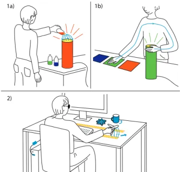
2)
1a) 1b)
Figure 1. CapNFC use-cases: (1a/b) Interacting naturally with every- day objects by transmitting object-related information through air or the human body, (2) using everyday objects to support blind users in interacting with a computer.
When choosing a communication method, developers have to accept certain trade-offs which include cost, form factors, and power consumption. This challenge becomes even more relevant when considering a high number of interactive ob- jects, which are supposed to be small, have heterogeneous form factors, run on a very limited power supply, and are re- quired to be low-cost. Technologies like RFID or NFC rep- resent a very suitable alternative to medium-range commu- nication, especially when the information is exchanged in a short-range spatial context. Moving from the inductive to the capacitive domain, a human’s conductive properties allow for indirectly incorporating the perception of body parts, touches and proximity into the communication technique. Especially in ubiquitous computing, this property leverages its full po- tential as a means for short-range communications using the air or the human body as a communication channel [39].
In this paper we present and discuss Capacitive Near-Field Communication - CapNFC - as an ultra low-power, touch- or proximity-mediated alternative to existing wireless com- munication techniques. Existing smart objects can be eas- ily adapted to use CapNFC as only a single microcontroller output pin is required for unidirectional communication. In terms of form factors, CapNFC is extremely flexible, sup- porting the integration into beds as well as small objects, such as body-worn sensors. CapNFC employs capacitive coupling between nearby conductive electrodes to transmit information over distances of up to 15 cm through air. Furthermore, the technology allows for communicating messages through the human body or measuring the proximity to human body parts.
It utilizes frequencies of 1 kHz to 1 Mhz, with wavelengths that are a multitude larger than the transmitting and receiving electrodes. Therefore, CapNFC acts in the quasi-electrostatic regime, eliminating the necessity for high-frequency design and complex hardware components. This results in a very small displacement current flowing from a transmitter to a re- ceiver electrode, enabling ultra-low power operation.
Capacitive coupling as a communication method has found interest in intrabody communications [39], information ex- change using touchscreens [35, 38] or access schemes in proximity sensing [28, 40]. Instead of focussing on a specific approach, we propose a generalized methodology for Capac- itive Near-Field Communication in UbiComp. Therefore, we offer the following contributions in our paper:
1. We introduce and evaluate a novel generic framework for Capacitive Near-Field Communications in ubiquitous en- vironments. We identify a set of operating modes and the corresponding interaction techniques.
2. Three case studies support the applicability of CapNFC in Ubiquitous Computing: (i) natural interaction paradigms with everyday devices, (ii) smart objects assisting blind users in interacting with their computer, and (iii) a smart bed with wearable sensors for sleeping behavior analysis.
The first two case studies are partly depicted in Figure 1.
3. We describe, compare and evaluate the concepts of Cap- NFC in sufficient detail to allow others to re-implement it.
Open-source schematics and source code enables the com- munity to quickly implement CapNFC applications.
GENERIC FRAMEWORK FOR CAPACITIVE NEAR-FIELD COMMUNICATION
CapNFC relies oncapacitive couplingbetween a transmitter and a receiver electrode [40]. Applying an alternating volt- age to one electrode and connecting the second electrode to ground causes a changing electric field between both elec- trodes. With CapNFC, the induceddisplacement current is measured on the receiver side. The energy-saving potential in ubiquitous communications can be regarded by physical con- siderations. CapNFC acts in the quasi-electrostatic regime and thus without any wave-propagation at its electrodes. This property solely enables a very small displacement current to flow from the transmitting electrode to the environment. In order to communicate by means of capacitive coupling, volt- ages oscillating at low frequencies (≤1 MHz) are applied to
the transmitter electrode. The receiver amplifies the induced displacement current and decodes the message. Various en- coding schemes may be used on top of this physical com- munication channel. Communication range and robustness depend strongly on the size of the transmitter electrodes and their voltages levels. Higher voltages increase the displace- ment current and lead to a better performance. Bigger elec- trodes allow for better capacitive coupling [13] but also pick up more background noise. In our examples, electrode sizes vary from 1 cm2to 100 cm2.
In this work, we apply the concept of CapNFC to ubiqui- tous interaction with everyday objects. Each object which is touched or manipulated by a user establishes an information flow and communicates its state to all objects within range.
Devices with extended interaction capabilities, such as smart- phones and computers, can interpret the information and gen- erate a response to object manipulations in their environ- ment. In the following, we discuss general operating modes, describe our reference implementation comprising hardware and communication protocol, present considerations for elec- trode placement, and document performance and energy con- sumption of our prototypes.
Operating modes
All communication techniques based on capacitive coupling do not only require a transmitter and receiver electrode, but also a connection to a common ground. Only when two ob- jects share a common ground, a displacement current is able to flow from one electrode to the other. A common ground may be established by sharing a ground between both circuits or by connecting each circuit to the environment’s ground.
However, as only very small displacement currents flow back and forth, CapNFC also works if a transmitter and a receiver are grounded via weak capacitive coupling to the environ- ment’s ground. This connection can be generated by a user touching the object, or a table on which the object is placed.
Many ubiquitous artifacts and devices are portable and must thus be battery-powered. Therefore, they lack a shared ground or direct connection to the ground, which is a pre- requisite for communication. Nevertheless, humans usually have good capacitive coupling to the environment’s ground [39]. Thus, establishing a common ground between two ob- jects can be achieved by embedding ground electrodes into the casing of an object and connecting the electrode to the bat- tery’s negative terminal. When a human touches the ground electrode or is in close proximity to it, capacitive coupling between the ground electrode and the environment’s ground is sufficiently strong to allow a displacement current to flow.
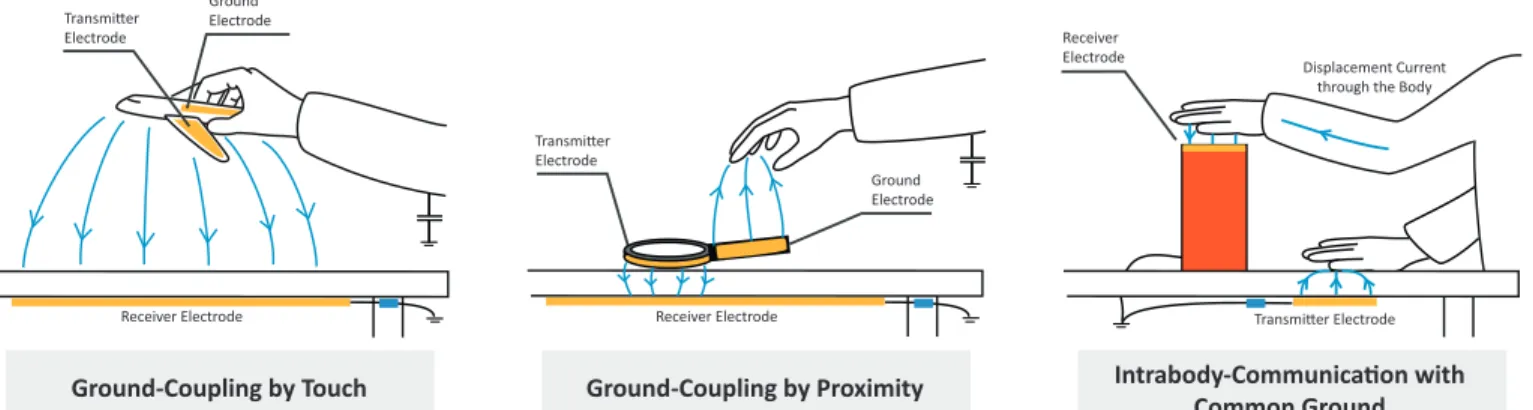
A very strong coupling to the environment’s ground, for ex- ample by directly connecting the objects to a grounded power supply, enables objects to communicate messages through the human body [39]. Based on these properties, we identified three different operating modes for CapNFC that allow for reliable data communication in ubiquitous environments, as depicted in Figure 2. The CapNFC framework embraces and utilizes the need for a common ground connection between sender and receiver by making it a central part of the sup- ported interaction methods.
Ground Electrode Transmitter
Electrode
Ground-Coupling by Touch
Transmitter Electrode
Ground Electrode
Intrabody-Communication with Common Ground Ground-Coupling by Proximity
Displacement Current through the Body Receiver
Electrode
Transmitter Electrode
Receiver Electrode Receiver Electrode
Figure 2. CapNFC offers three operating modes that depend on the ground-coupling of objects: Ground-coupling by touch for indirect touch recogni- tion, ground-coupling by proximity for sensing a person approaching an object, and sharing a common ground for intrabody-communication.
Ground-Coupling by Touch
In this mode, the receiver object is connected to the environ- ment’s ground, and the transmitter is a battery-powered ob- ject. Besides the transmit electrode located in the smart ob- ject, a small additional electrode is connected to the battery’s negative power supply. Whenever the user is in very close proximity to this electrode or touches it, the weak capacitive coupling to the grounded human body enables an informa- tion flow from the transmitter to the receiver. Therefore, the ground electrode indirectly acts as capacitive touch sensor.
Ground-Coupling by Proximity
In this operating mode, a receiver is connected to the envi- ronment’s ground, and a battery-powered smart object is lo- cated in close proximity to the receiver. In addition to the transmitter electrode, the battery-powered object has a built- in ground electrode. When the user approaches this electrode with a body part the capacitive coupling to the environment’s ground increases. By measuring the signal strength in the re- ceiver, it is possible to recognize an approaching human hand in distances up to 15 cm.
Intrabody-Communication with a Common Ground
When both objects are directly connected via a common ground, an information flow can be established through the user’s body [39]. This enables the user to touch two ob- jects and thus establish communication between both of them.
In CapNFC, this mode is primarily applicable for station- ary installed objects, as they may be directly connected to a grounded power supply.
Figure 3. Two different CapNFC components: A tag (right) with an embedded accelerometer and a transceiver (left). The hardware is only partly equipped to allow for experimenting with active sending filters.
Reference Implementation
The CapNFC concept can be adapted for a multitude of appli- cations. However, we believe that ubiquitous user interfaces benefit the most from CapNFC. Before designing the Cap- NFC reference hardware and software, we defined constraints that must be fulfilled in order to allow for a high number of low-cost smart objects: (1) transmitting information should not require any additional active hardware components (crys- tals, amplifiers, ...) except for a single microcontroller; (2) re- ceiving information must consume a low amount of process- ing power and energy; (3) the method has to be suitable for low-power microcontrollers that run on frequencies as low as 1 MHz. For Ubiquitous Computing, we prioritize these goals over a high data rate.
Based on these design-centered decisions, we implemented two hardware components: a transceiver and a low-power transmitter tag, as shown in Figure 3. The transceiver comprises a microcontroller (MSP430G2553), a serial-to- USB converter (FT230XS), an operational amplifier IC (OPA2344), and a voltage regulator (TPS79733). It can be connected to a PC or smart phone via USB. The tag contains only a low-power microcontroller (MSP430G2352) and an accelerometer (ADXL345). It is powered by a 3 Volt coin cell monitored by a voltage regulator (TPS79730). The tag can be attached to an object and is only able to transmit pre- defined and context-dependent messages via capacitive cou- pling, using all three modes identified in the previous section.
The accelerometer allows saving power and supporting ges- tural interaction with a tagged object. It activates CapNFC communication whenever the tag is moved or a pre-defined gesture is detected.
Communication Method and Protocol
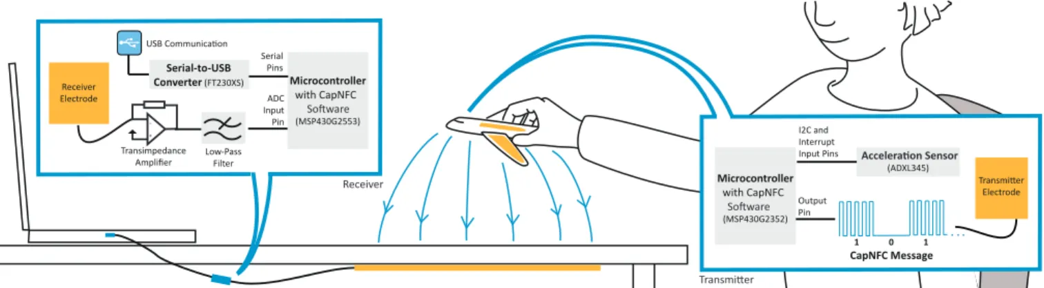
Figure 4 shows an exemplary CapNFC communication setup.
The communication principle itself is based on broadcasting messages; the range around an object can be represented by a spatial context on which messages of predefined types are published. Components may also publish higher level infor- mation composed of previously received as well as data mea- sured by themselves.
Due to the design constraints and the limited communication space, we decided not to include carrier-sense multiple access
Microcontroller with CapNFC (MSP430G2352)
Output Pin
0 1
1
Electrode (ADXL345)
I2C and Interrupt Input Pins
CapNFC Message
+ -
Microcontroller with CapNFC (MSP430G2553) InputADC
Pin Serial-to-USB Converter (FT230XS)
Serial Pins Receiver
Electrode
Transimpedance Amplifier Low-Pass
Filter
Software
Software
Acceleration Sensor
Transmitter Receiver
Figure 4. An exemplary CapNFC setup: A toy airplane communicates with a computer by transmitting its movement related data using a quasi- electrostatic field. The airplane is equipped with a low-power CapNFC tag, consuming 280µAin total while transmitting a message. The receiver amplifies the induced displacement current, decodes the messages and hands them to the computer via USB.
techniques (CSMA) to avoid collisions when multiple trans- mitters access the communication medium. Instead, the exis- tence of data transmission collisions is accepted deliberately in our protocol. This fact enables smart objects that solely employ a low-cost microcontroller without additional hard- ware. These objects are only capable of transmitting mes- sages, without being able to receive any information from other objects. Due to this simple concept, existing smart ob- jects can be easily extended to support CapNFC communica- tion as only a single additional output pin at a microcontroller is needed.
Information is transmitted via a 3.0-3.3 V rectangular-shaped signal, oscillating at a frequency of 10 kHz. The signal can be easily created using a microcontroller’s pulse-width- modulation module, which is a common functionality even in low-cost hardware. In order to represent binary informa- tion, the signal is switched on and off (On-Off-Keying), al- lowing for a data rate of 2 KBit/s. As illustrated in Figure 5, a message begins with two high bits which represent a start condition, followed by a synchronization byte of succeeding 1-0 transitions (0xAA), the length of the message (1 byte), the message type (1 byte), a sender address and a succeeding payload (less than 30 bytes including parity bytes). The rea- son for the payload length limitation lies in potential clock- drift among the different hardware components. The receiver of a message synchronizes with each 1-0 and 0-1 transition.
However, when the number of transitions is low, the clock- drift would be too high for payloads longer than 30 bytes.
Data Length 8 Bit Start 10 Bit
Data 0 – 20 Bytes Sender
8 Bit
0x03 6
0xAA 0x12 10
6 Byte
Sync Sender Address of
Magnifier Glass
Acceleration x-axis (2 Byte)
-15 Acceleration
y-axis (2 Byte)
140 Acceleration
z-axis (2 Byte) Type
8 Bit
0x01 Inertial Sensor
0x03 3
0xAA 0x20 255
3 Byte
Sync Sender Address of
Mobile Phone Red (1 Byte)
50 Green (1 Byte)
50 Blue (1 Byte) 0x20
Color Picker
Figure 5. Our CapNFC communication protocol. The message format can be seen on top, two exemplary messages below. All messages are secured with parity bytes for bit error correction.
In order to receive data, which is optional in CapNFC, a receiver employs a transimpedance amplifier followed by a low-pass filter [28]. It requires three simple hardware com- ponents - a low-cost operational amplifier, two resistors and a capacitor. The receiver’s microcontroller samples the signal at 40 kHz, and reconstructs the transmitted information with the Goertzel algorithm [12]. This computationally inexpen- sive algorithm is used to detect the presence of the transmit- ted signal oscillating at 10 kHz. In the following, parity bytes are used to restore potentially corrupted bits and an optional CRC checksum ensures the integrity of a message.
Electrode Placements
As stated in the introduction of CapNFC operating modes, communication between two objects requires a weak capac- itive coupling to a common ground. Besides connecting the object directly to a common ground, a weak ground coupling can be set up by a human touching or approaching a ground electrode. In order to establish a suitable coupling to the en- vironment, this electrode is attached to the object’s negative supply voltage and placed near the object’s surface or directly connected to conductive parts of the object. In his work about Personal Area Networks, Zimmerman determined a capaci- tance of 110 pF [39] for a current flowing from an isolated human body to the environment’s ground.
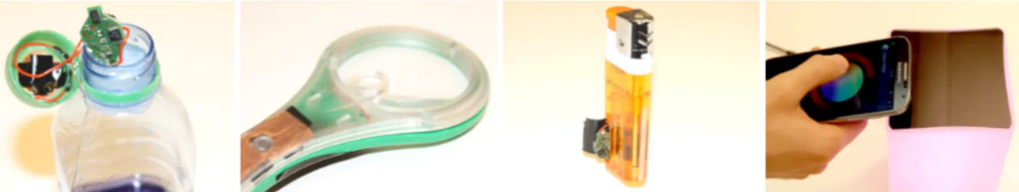
If the object is only supposed to communicate while being touched or when a hand is in proximity, it is necessary to place a small electrode somewhere near the regions the hand approaches. The bigger the ground electrode gets, the bet- ter a displacement current is able to flow from the transmitter electrode to a different object’s receiver electrode. Transmit- ting information without physical touch can be realized by placing an electrode close to other objects having an indirect connection to the environment’s common ground, for exam- ple a table’s wooden surface. The ground electrodes may also be isolated or located within the object as it is only necessary that alternating current is able to flow. In the easiest scenario, the transmitting or receiving electrodes of a CapNFC-enabled object are the object’s conductive body itself. However, elec- trodes can be constituted of different materials, for exam- ple conductive threads, aluminum foil, transparent ITO lay-
Figure 6. Different electrode placements: (1) The transmitter electrode is placed directly under the bottle cap, (2) the magnifying glass has a big ground electrode in the region where the user touches the object, the transmitter electrode is placed around the glass, (3) the lighter uses its conductive part as a transmitter electrode, and (4) the mobile phone’s transmitter electrode is placed at its back, the lamp’s receiver electrode is under the black surface.
ers or inkjet-printed silver [17]. The low surface conductivity of transparent or printed materials themselves decreases the performance of capacitive coupling applications only slightly [13]. This fact can also be transferred to capacitive communi- cations and enables a designer to choose from a wide variety of materials with different properties. Figure 6 shows pos- sible electrode locations and placements of some exemplary CapNFC components.
Performance Evaluation
We evaluated the performance of the presented communica- tion method by assessing our reference implementation with different tagged objects having uni- and bidirectional com- munication abilities. The experiments were carried out in a standard living environment, with the objects being placed on a wooden desk. As a performance indicator, the signal-to- noise ratio (SNR= 10 log10(Psignal/Pnoise)) was applied. In the following, we present evaluation results for all three Cap- NFC operating modes.
Figure 7 depicts the SNR for different transmitter/receiver distances employing ground-coupling by touch. Therefore, we combined two copper electrodes of different sizes and cross-evaluated the SNR. Interestingly, the evaluation re- vealed that one should rather use larger transmitter electrodes, than enlarging the size of the receiver electrode. Enlarging the receiver electrode’s size will result in a greater amount of noise, whereas the strength of the received signal does not increase proportionally. This is a negative property for ubiq- uitous interaction, as it is very difficult to increase the trans-
0 5 10 15
0 10 20 30 40 50 60
Transmitter−Receiver Electrode Distance [cm]
Signal−to−Noise Ratio [dB]
TX 1cm2, RX 1cm2 TX 1cm2, RX 4cm2 TX 4cm2, RX 1cm2 TX 4cm2, RX 4cm2 TX 9cm2, RX 4cm2 TX 9cm2, RX 9cm2 SNR = 5dB
Figure 7. Ground-Coupling by Touch: The Signal-To-Noise Ratio with different receiver/transmitter distances and electrode sizes. The 5 dB SNR threshold results in a bit error rate (BER) of more than 20%, which means that many messages are corrupted.
mitter electrode’s size in small battery-powered objects. En- larging the receiver electrode’s size, which may be located under the desk, is usually easier as the space is not as con- strained. Depending on the electrodes’ sizes, messages can be transmitted in hand distances up to 15 cm.
Figure 8 depicts the evaluation results forground-coupling by proximity. In this experiment, we use a battery-powered tag with differently sized ground and transmitter electrodes, located in close distance to a receiver with a corresponding large receiver electrode. A human hand was used to approach the ground electrode at different distances with multiple rep- etitions of the experiment. The experiment shows that the de- tection distance increases with larger ground electrodes. The evaluation of larger ground electrodes revealed that the weak coupling to the environment’s ground, for example the table, is sufficient for transmitting messages. In these cases, the SNR remains constant even after removing the hand. Alas, inferring a certain distance from a given SNR requires strong initial assumptions about the object’s location and orienta- tion. Nevertheless, differences in the SNR between succeed- ing messages can be exploited to detect hand presence and proximity differences.
The evaluation results forintrabody with common groundare depicted in Figure 9. We evaluated different touch types for coupling a transmitter and a receiver electrode. Therefore, we isolated each electrode under a wooden surface and touched it with one, two, three fingers, and the whole hand. Surprisingly to us, the SNR was not affected very strongly when touching
0 5 10 15
0 5 10 15 20 25 30 35 40
Hand Distance to Ground Electrode [cm]
Signal−to−Noise Ratio [dB]
Ground 1cm2, TX 1cm2 Ground 1cm2, TX 4cm2 Ground 4cm2, TX 1cm2 Ground 4cm2, TX 4cm2 Ground 9cm2, TX 4cm2 Ground 9cm2, TX 9cm2 SNR = 5 dB
Figure 8. Ground-Coupling by Proximity: The object is placed in little distance to the receiver electrode. The diagram shows the SNR for dif- ferent ground and transmitter electrode sizes. By approaching the hand to the ground electrode, the SNR increases.
1 finger 2 fingers 3 fingers whole hand 102
104 106 108
Signal/Noise Strength (integer)
Type of Intrabody Coupling Receiver Average Signal Strength Receiver Average Noise
Figure 9. Intrabody with Common Ground: The signal/noise strength is given as an integer value, representing the average result after comput- ing a window with the Goertzel algorithm.
the electrodes with more fingers. However, when analyzing the signal and the noise levels separately from each other, the signal as well as the noise levels increase when the coupling is made through a larger area, e.g. a hand. This interesting property is very useful for gesture or grasp recognition, for example by remotely detecting when a finger was added or removed from an object.
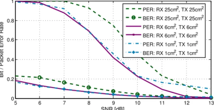
Figure 10 shows the relation between SNR, bit error rate (BER) and packet error rate (PER) in our reference imple- mentation. The PER does not only depend on the BER af- ter error correction, but also on the detection of the message preamble, which is currently not fault tolerant. When using larger receiver electrodes, the already high noise variance in- creases and leads to a decreased BER and PER. Possible rea- sons can be seen in noise generated by devices operating at similar frequencies, e.g. switch-mode power supplies.
In the following, we discuss the energy consumption of Cap- NFC and our reference implementation. The energy required for succeedingly loading and unloading the capacitance be- tween transmitter electrode and grounded parts has only lit- tle influence on the implementation’s energy consumption.
This fact is very important, as it only adds little energy con- sumption to existing systems while leveraging communica- tion abilities based on capacitive coupling. Moreover, in the future this property allows for creating tags powered by energy-harvesting or capacitive power transfer [20], very sim-
5 6 7 8 9 10 11 12 13
0 0.2 0.4 0.6 0.8 1
SNR [dB]
Bit / Packet Error Rate
PER: RX 25cm2, TX 25cm2 BER: RX 25cm2, TX 25cm2 PER: RX 6cm2, TX 6cm2 BER: RX 6cm2, TX 6cm2 PER: RX 1cm2, TX 1cm2 BER: RX 1cm2, TX 1cm2
Figure 10. The relation between SNR, the bit and packet error rate in the region from 5 -13 dB. The packets had a data length of 3 byte (+1 byte sync) secured with 3 parity bytes ((8,4)-Hamming).
ilar to RFID. Basically, only a very simple low-power micro- controller is necessary to transmit data. For example, while transmitting 10 inertial samples per second, our low power tag consumes less than 88µAat 3.0 V on average. Receiving messages requires an additional operational amplifier, which consumes 750µAin our implementation and a more power- ful microcontroller for signal processing. However, the en- ergy consumption of a receiver can be reduced further by choosing a different amplifier. Currently, our amplifier sup- ports a very high slew rate to experiment with significantly higher frequencies than 10 kHz. In terms of energy consump- tion, it can be concluded that CapNFC supports extremely low-power implementations, especially suitable for the usage in smart, energy-constrained, objects. A comparison of Cap- NFC with other technologies, such as RFID, will be given in the next section.
RELATED WORK AND COMPETING TECHNOLOGIES Capacitive Communications and Sensing
Using capacitive coupling for information exchange is ap- plied in a wide variety of application scenarios. Amongst oth- ers, it is used for communication between objects and multi- touch enabled devices [35, 38], and communication via the human body [39]. Prototyping capacitive sensing applica- tions has made significant advances in the last years due to inkjet-based printing [7, 17] or low-cost foil cutters [26].
Capacitive Coupling through Air and Direct Contact
Some prototypes of tangible objects allow sending short mes- sages to a device with a capacitive touchscreen by simulating touch events [35, 38]. The presented communication tech- nique works with arbitrary capacitive touchscreens and re- quires only simple hardware for the sender that is integrated into a finger ring. Obviously, the communication is unidirec- tional from the sender to the multi-touch device and has a low bandwidth limited by the scanning frequency of the touch- screen. In the domain of indoor user localization, Valtonen et al. use conductive tiles on which the human body acts as a transmitter electrode [34]. A receiver placed on the ceil- ing or within a wall identifies the tiles a user steps on. Cohn et al. presented a gesture recognition system based on elec- tric fields produced by devices within the user’s home envi- ronment [5, 6]. In contrast to the methods discussed before, the human body acts as a receiver electrode while a wearable hardware component analyzes the received signal.
Intrabody Communication
Capacitive coupling can also enable two devices to ex- change information using the human body as a communica- tion medium [11, 39]. This principle was firstly investigated by Zimmerman for realizing Personal Area Networks [39].
In his work, he points out that all communicating nodes re- quire not only a capacitive coupling to the human body but also a coupling to a common ground potential. Since then, this principle was picked up by many researchers, for exam- ple to identify different users at a touch screen [8]. Park et al. proposed the Touch and Play (TAP) system [23] for creat- ing a link between media storage devices and output devices through the human body. In a concrete application scenario, a photo was transferred from a digital camera to a printer.
Proximity and Grasp Sensing using Capacitive Coupling In the domain of proximity sensing, capacitive coupling can be used for recognizing gestures [14, 28], sensing user loca- tions [29] or their activities [13, 37]. Also, capacitive sens- ing was used in wearable devices to measure muscle contrac- tions for activity recognition [4]. The approaches rarely trans- mit information, they rather use traditional capacitive sens- ing techniques. However, modulation approaches like code- division multiple access or frequency-division multiple ac- cess can also be found in this domain [13, 28]. In order to dis- cern different ways a user touches an object, capacitive sens- ing technology such as swept-frequency capacitive sensing [15, 25] or time-domain reflectometry [36] were employed.
Competing Communication Technologies Long-Range Wireless Communication
The most important difference between CapNFC and long- range wireless communications can be seen in the supported transmission range and energy consumption. Technologies like Bluetooth or ZigBee support transmission ranges of 1 - 100 m, whereas CapNFC usually operates in a range up to 15 cm. Compared to wireless communications, CapNFC is easier and cheaper to implement, and consumes significantly less energy while transmitting and receiving data. On the other hand, using wireless communications offers several ad- vantages like a full-duplex communication stack, greater dis- tances and higher data rates. Therefore, the desired commu- nication range, constraints in energy consumption and com- munication abilities are the most important decision factors.
Inductive RFID / NFC
In contrast to Capacitive NFC, Inductive NFC (RFID) has found many applications due to its commercial breakthrough and available passive tags. RFID was used in smart envi- ronments for interacting with everyday objects, for exam- ple coupling a mobile phone to a stereo device [3] or en- abling an information flow between touch-enabled surfaces [10]. Moreover, it is used as a bridging technology for es- tablishing a confidential pairing with other wireless com- munication services and for mobile micropayment solutions [9]. In the following, we compare the power consumption of our CapNFC implementation to an ultra-low power RFID (NFC) implementation given in [32]. Prior to this discussion it must be noted that both implementations have very differ- ent levels of technological maturity and RFID’s communica- tion concept provides more elaborate features [21]. RFID re- lies on a reader-central infrastructure supporting passive tags, whereas CapNFC’s communication mechanism is based on broadcasting and a decentralized infrastructure. Also, the data rates strongly differ between both exemplary implemen- tations (CapNFC: 2kBit/s; RFID/NFC: 424kBit/s) [32].
In order to compare the two approaches, we apply a sim- plified measure of energy consumption per bit Ebt =
Energy Consumption
Maximum Data Rate. When transmitting, our CapNFC implemen- tation’s energy consumption is lower (360 nWs/Bit) than the given RFID implementation (825 nWs/Bit) [33]. While the RFID reader requires more than twice the energy per bit, it is also able to power passive tags, which CapNFC does not do.
A comparison of both communication channels, i.e. ignoring
the peripherals’ energy consumptions, shows a larger differ- ence. An output energy of 235 nWs/Bit is typical for RFID [31, 33]. CapNFC’s output energy varies from 0.225 nWs/Bit while transmitting through air to 2.475 nWs/Bit while trans- mitting through the human body. This suggests that more mature CapNFC implementations can lead to an energy con- sumption which is many magnitudes smaller than RFID. The main reason is the small amount of energy needed to charge the capacitance between transmit electrode and environment.
CapNFC’s energy consumption while receiving information is mainly induced by the transimpedance amplifier and the signal processing on the microcontroller. As we did not op- timize the transceiver board for low-power operation, signal processing leads to an energy consumption of 7.5µWs/Bit.
Nevertheless, we expect a great potential for reducing energy consumption in the receiver part.
Due to CapNFC’s early development stage, only few ap- proaches have been made to create passively powered com- munication devices. However, power transmission using ca- pacitive coupling, as employed in [20], proves the potential of passively powered capacitive sensor tags. Even though the comparison of energy consumption between both tech- nologies is very difficult, especially the low energy consump- tion for transmitting information features CapNFC for use in ultra-low power devices with unidirectional communication abilities. We also see potentials in the combination of energy harvesting techniques [22] to realize passive tags.
RFID does not require a common ground between communi- cating nodes which is desirable for many applications How- ever, the need for establishing a capacitive coupling to a com- mon ground in CapNFC enables numerous opportunities for embedding interactive properties in an interaction system, as described in the technical framework section. The different CapNFC operating modes allow for intrabody communica- tion, proximity awareness and indirect touch sensing. Com- paring CapNFC’s electrode placements to the placements of RFID antennas, one can achieve similar form factors, as de- scribed in the technical evaluation and the following case studies. The need for a common ground in CapNFC requires an additional ground electrode, raising the complexity of tag- ging an object. A very interesting property in CapNFC is the equipment of large objects with communication abilities, which would require multiple RFID readers. For example, a bed can be equipped with simple conductive wires to build a large receiver area. In conclusion, the decision of using Cap- NFC or RFID strongly depends on the application scenario, an overview of our discussion is outlined in Figure 12.
Inductive RFID / NFC CapNFC
+ Tagging of objects is - Flexibility and operating modes
very simple introduce complexity
- Large objects are not + Very flexible for different object sizes easy to tag using conductive parts as electrodes - Limited interaction + Proximity & indirect touch
modes sensing, intrabody communication
+ Passive tags are available o Passive tags can be realized - High peak currents during + Very energy-efficient information
communication exchange
+ No ground-coupling is required - At least two electrodes needed Figure 12. Comparison of RFID with CapNFC properties for UbiComp.
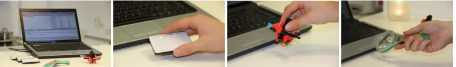
Figure 11. An exemplary workplace equipped with CapNFC-enabled objects for symbolic access to a very specific set of computer functionality. The transceiver is connected to the PC, having a receiver electrode placed under the user’s desk.
CASE STUDIES: CAPNFC IN UBIQUITOUS COMPUTING Sensing object manipulations in combination with Capacitive Near-Field Communication offers an elegant solution for per- ceiving a user’s environment as well as interesting ubiquitous interaction opportunities. CapNFC has a number of useful properties that are highly desirable in Ubiquitous Computing:
1. Instantaneous, infrastructure-free communication: Using CapNFC, interaction is independent from a server-based infrastructure or central access points. Instead, a mul- titude of devices within range communicates instanta- neously based on a stateless communication protocol.
2. Natural interaction: A user can directly identify and com- bine the objects required for interaction. By employing ad- ditional sensors within an object, the knowledge of object manipulations and movements can be exploited and pub- lished in a short-range context. Combining the different CapNFC operating modes can be utilized for enriching the interaction, for example by detecting touch, proximity or communicating messages through the human body.
3. Low energy consumption: Capacitive Near-Field Com- munication requires significantly less energy than high- frequency wireless communication.
4. Low hardware requirements: Transmitting information is as easy as toggling a pin on a microcontroller, without re- quiring any additional integrated circuits. Moreover, the layout of transmit and receive electrodes is very flexible in terms of materials, shapes and sizes.
In the following, we present three case studies that benefit from CapNFC and combine the different operating modes in a useful way. In the first use-case, we present a real-world example where blind users interact with a PC using tangible objects. The second use-case is a conceptual study of natural interaction with an everyday object. Thirdly, we present an activity recognition system for sleeping analysis.
Cast Study 1: Tangible Interaction for the Blind
In this case study, we present a prototypical implementation of a tangible interaction system for visually impaired users.
Especially for this target group, tangible objects provide an easy and intuitive way of symbolically accessing computer functions [19, 24]. To develop a feasible and ergonomic so- lution, we work in close cooperation with a company special- ized in developing products for the blind.
In order to use a computer efficiently, blind people are obliged to learn a high number of keyboard shortcuts and commands
that are used to automate the computer. Symbolic access methods that link tangible objects to computer functions can help those people to execute a very specific set of actions, such as opening the weather report or reading their emails.
Especially when considering the usage scenario of control- ling continuous system properties, such as the reading speed of a screen reader, the usage of tangible objects employing CapNFC enables a very fast and natural way of interaction.
Figure 11 shows different tangible objects that were realized for this use-case. A transceiver is connected to a PC and the receiver electrode is deployed under the desk. The first ob- ject we realized is a plastic card with braille text. Each card represents a command that is carried out by the computer, for example ’list running applications’. Therefore, when the card is being touched (ground-coupling by touch), the card’s ID and its acceleration data can be sent to the computer. When the card is successfully identified, a double tap on the card executes the corresponding command. The second object is a toy airplane used for regulating the reading speed of the screen reader. Leaning the plane forward and backward in- creases and decreases the speed. The third object - a mag- nifying glass - operates in two modes: touch and proximity.
When the user tries to find the magnifying glass on the desk, the computer is able to play a sound when the hand moves over it. When the glass is touched, it can be leaned in two directions to control the position of the screen magnifier. By employing the signal-to-noise ratio at the receiver, the mag- nification level can be increased and decreased depending on the glass’s distance.
As the behavior of each object is very specific, we imple- mented context-sensitive audio hints for each object by shak- ing it. Moreover, acoustic notifications indicate when an ob- ject was successfully recognized or when the object is put away. Our interviews and initial experiments with three blind users revealed that the setup must be chosen very carefully, according to the target person or group. As the initial learning process of keyboard-based systems is very difficult, elderly, children, and persons with multiple disabilities represent a suitable target group for the system. People who are solely vi- sually impaired and have no difficulties in learning are prob- ably not going to benefit from the system, as a high produc- tivity can only be achieved when using keyboard shortcuts.
Nevertheless, in working life, computer workplaces for blind persons are often equipped with highly specific hardware, in which certain tangible objects could complement traditional interaction methods. The long battery life and very low cost of CapNFC-enabled tangible objects represent very important factors for the acceptance of the tangible interaction system.
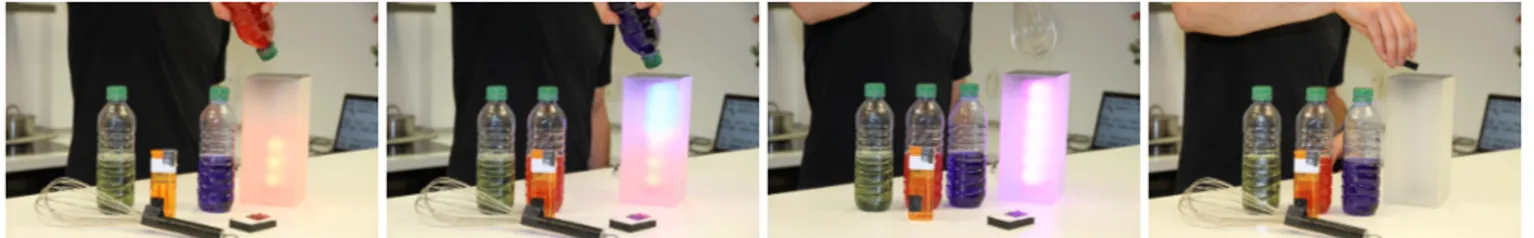
Figure 13. An exemplary workflow for interacting with a smart lamp: The bottles are used to virtually fill up the lamp with the corresponding color.
Moving the whisk above the lamp will mix the colors, whereas a gesture with the rubber gum switches off the lamp.
Besides the interviews, we evaluated different objects in- volved in the case study to demonstrate the suitability of CapNFC communication. Therefore, we observed the SNR as well as the bit-error-rate before data correction (BER =
# incorrect bits
total # of bits). Our measurement results are listed in Figure 14, showing that communication for ground-coupling by touch is very reliable for object distances of 5 cm. As both evalu- ated transmitting objects have rather small electrodes reach- ing from 1 cm2 to 2 cm2, the SNR drops to less than 3 dB at distances above 8 cm. Ground-coupling by proximityeas- ily allows for recognizing when a hand approaches the mag- nifying glass. Therefore, the object’s ground electrode was chosen to be 3 cm2. As depicted in the table, it enables a de- veloper to reliably detect an approaching hand at distances of 5 cm. Due to the bigger ground electrode, the magnifying glass is sufficiently grounded by the table to retain communi- cation abilities without human presence.
Case Study 2: Interaction with Everyday Objects
As computing and communication technologies advance, more and more household devices and tools gain ’intelli- gence’ and extended configuration possibilities. For example, lamps with adjustable light color and/or time-dependent light- ing patterns have been commercially available for some time.
However, such advanced features also require more powerful user interfaces in order to leverage their capabilities. Many users usually suffer from poorly designed interfaces, which induced us to transfer a natural interaction technique on a conceptual lighting control.
Figure 13 depicts a way users may naturally interact with the lamp. Therefore, different objects were equipped with Cap- NFC tags, whereas the lamp employs a transceiver. We stored CapNFC tags in the bottle caps of three bottles filled with dif- ferently colored water. When the user moves a bottle cap into the proximity of the lamp, the tag’s acceleration values can
Operating Mode
Receiver Sender SNR
[dB]
BER
Ground- coupling by touch
Laptop (electrode in the desk)
Braille Card
(object distance 5 cm) 10.47 2.50%
Airplane
(object distance 5 cm) 11.40 1.40%
Ground- coupling by proximity
Laptop (electrode in the desk)
Magnifying Glass
(hand distance 1 cm) 8.56 4.17%
Magnifying Glass
(hand distance 2 cm) 7.93 4.39%
Magnifying Glass
(hand distance 5 cm) 6.82 7.40%
Figure 14. Case study 1 - signal-to-noise ratio and bit error rate evalua- tion for different tangible objects above a table.
be received by the lamp. When the bottle is leaned in the way someone would do to pour out water, the lamp starts filling up in the color of the bottle’s contents. The ground-coupling is achieved by a small conductive silver wire, which is touched by the user’s hand. A rubber is used to erase the lamp’s con- tent, making use of the internal accelerometer. It also fea- turesground-coupling by proximitywhen being placed on the lamp’s surface. In this case, approaching the rubber in dis- tances up to 10 cm turns the lamp either on and off. More- over, objects like a lighter or a whale are able to trigger spe- cific lighting profiles like fire or ocean animations. We also placed three transmit electrodes, representing red, green and yellow, on the table. The three tags were connected to the common ground, enabling them to transmit messages through intrabody communication. As soon as the user touches both the lamp and the colored region, the lamp will fill up with the selected color. Using a mobile phone with a transceiver on its back allows the user to directly transmit color values to the lamp using a color picker. In this setup, the device is automatically grounded when touching its metal case.
Figure 15 shows an evaluation of the smart objects involved in the case study. Despite the small transmitting electrode, the lighter showed a very good performance enabling communi- cations in distances up to 10 cm. Here, the lighter’s conduc- tive cap was used as a transmit electrode, which even works when the flame is enabled. In the future, we plan to exploit the increasing signal level when usingintrabody communi- cationto adjust the lamp’s brightness by adding and remov- ing fingers on its surface. The individual signal levels make it difficult to classify such gestures, as the signal has vary- ing offsets influenced by skin conductivity and differences in the contact area. To conclude, this case study underlines the possibility of implementing new interaction paradigms with CapNFC by combining arbitrary objects to realize a natural way of interacting with everyday objects.
Operating Mode
Receiver Sender SNR
[dB]
BER
Ground- coupling by touch
Lamp
Bottle
(object distance 5 cm) 9.36 4.14%
Lighter
(object distance 5 cm) 10.06 1.91%
Intrabody with common ground
Lamp
Colored Area
(coupling with 1 finger) 9.69 2.33%
Colored Area
(coupling with 2 fingers) 9.92 2.95%
Colored Area
(coupling with 1 hand) 10.50 1.60%
Figure 15. Case study 2 - evaluation of communication properties for interacting with everyday objects.
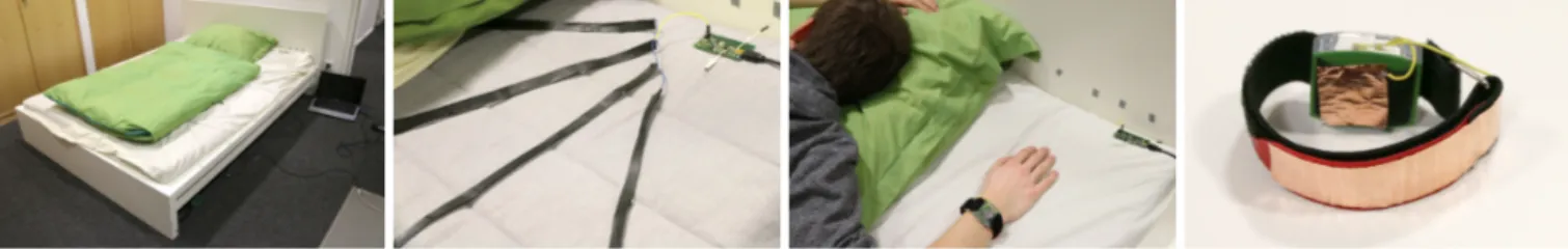
Figure 16. A bed that is able to receive messages from multiple body-worn sensors, for example a wrist-worn accelerometer. The accelerometer is grounded using ground-coupling by touch (inner electrode) and transmits its sensor values to the bed (outer electrode).
Case Study 3: Activity Recognition and Wearables Activity recognition in combination with wearable and sta- tionary sensors has been an emerging research topic for the past decade. Various approaches led to a wide variety of sensor-based approaches, for example to recognize activities of daily living [1, 18, 30] or studying various types of sleep- ing behavior [2, 27].
Transmitting information from multiple sensors to a smart bed can be used for online activity recognition or transfer- ring sensor data collected during the day. Communication distances from the human body to a bedcover are very short, and are therefore well-suited for using CapNFC. In order to demonstrate CapNFC’s potentials for sleep recognition, we built a smart bed in combination with a wearable sensor as de- picted in Figure 15. The bed incorporates a transceiver with long electrodes placed under the bedcover. The wrist-worn accelerometer periodically reports its sensor data to the bed.
It appliesground-coupling by touchwith ground electrodes placed near the user’s skin and a transmit electrode placed on the wristband’s outer part. Furthermore, different regions in the center area near the thigh were equipped with stationary electrodes, transmitting information throughintrabody com- municationwhen the person lies on them for identifying ac- tive regions. This arrangement exemplifies one of CapNFC’s strengths: The supported flexible electrode layouts allow for easily equipping large objects with communicational abili- ties. Due to the different operating modes it is possible to join both, stationary and wearable sensing.
Figure 16 shows the properties of the communication link be- tween the bed, the wristband, and the stationary electrodes.
We evaluated two electrode materials within the bed, multi- ple conductive threads and tiny copper bands placed under- neath the bed sheet. Despite the bigger area covered by the
Operating Mode
Receiver Sender SNR
[dB]
BER Ground-
coupling by touch
Bed (copper)
Wristband
(object distance 1 cm) 20.31 1.12%
Wristband
(object distance 8 cm) 11.79 1.38%
Ground- coupling by touch
Bed (thread)
Wristband
(object distance 1 cm) 17.65 1.52%
Wristband
(object distance 8 cm) 11.85 1.84%
Intrabody with common ground
Bed (copper) Stationary transmitter
(copper) 16.67 1.61%
Figure 17. Case study 3 - communication performance for stationary and wearable objects communicating with a smart bed.
copper bands and their outstanding conductivity, the perfor- mance is very similar to using conductive threads. Conduc- tive threads provide a lot of advantages in this case, they are very flexible and can be integrated easily into different kinds of fabric. The evaluation also shows that it is feasible to com- bine body-worn and stationary appliances to measure bedding postures and fine-grained physical parameters. Nevertheless, when considering wearable devices the data link may always be interrupted by posture changes. Also, using many highly active devices leads to a high number of message collisions.
CONCLUSION & FUTURE WORK
As shown in our case studies, CapNFC has proved to be a very suitable technology for ubiquitous interaction and per- ception. Using CapNFC, it is possible to bridge the gap be- tween a high number of smart objects, low cost, low power consumption and highly interactive system designs. There- fore, the technology represents a suitable companion to RFID with many exciting benefits in interaction design. The imple- mentation is still in a very early stage, heading towards many types of possible applications. A combination of wearable and stationary sensors, as described in the last case study, rep- resents one of the most interesting aspects for future research.
Due to the currently high noise variance, high SNRs are re- quired to obtain a good packet error rate. Besides lowering error rates, more noise-resilient communication methods can also extend the interaction range to 30 cm. In particular, we plan to apply frequencies greater than 100 KHz and use syn- chronous undersampling to restore the signal [28]. Increas- ing the carrier frequency will make the signal less prone to noise produced by other electronic devices. Moreover, we will investigate more sophisticated modulation methods like spread-spectrum modulation to avoid problems with narrow- band noise [28]. We currently also work on significantly smaller tags and transceivers which consume less power.
Our central contribution in this work is the identification of a CapNFC framework with three operating modes based on different types of ground-coupling. It enables smart objects to communicate in distances of 15 cm through air, measur- ing the proximity to human body parts in distances up to 15 cm, and exchanging information through the human body.
We discussed the properties of CapNFC, evaluated them in a quantitative manner and presented three case studies proving the suitability of CapNFC in Ubiquitous Computing. More- over, we support others to implement their own applica- tions by providing source-code, schematics and materials at http://www.opencapsense.org/capnfc.
REFERENCES
1. Amft, O., Junker, H., and Tr¨oster, G. Detection of eating and drinking arm gestures using inertial body-worn sensors. InISWC ’05, IEEE (2005), 160–163.
2. Borazio, M., and Van Laerhoven, K. Combining wearable and environmental sensing into an unobtrusive tool for long-term sleep studies. InACM SIGHIT symposium on International health informatics - IHI
’12, ACM (2012), 71–80.
3. Chen, L., Pan, G., and Li, S. Touch-driven interaction via an NFC-enabled smartphone. InPerCom ’12 Workshops(2012), 504–506.
4. Cheng, J., Amft, O., and Lukowicz, P. Active capacitive sensing: Exploring a new wearable sensing modality for activity recognition. InPervasive ’10(2010), 319–336.
5. Cohn, G., Morris, D., Patel, S., and Tan, D.
Humantenna: using the body as an antenna for real-time whole-body interaction. InCHI ’12(2012), 1901–1910.
6. Cohn, G., Morris, D., Patel, S. N., and Tan, D. S. Your noise is my command: sensing gestures using the body as an antenna. InCHI ’11(2011), 791–800.
7. Crispin, X., Jakobsson, F. L. E., Crispin, A., Grim, P.
C. M., Andersson, P., Volodin, A., Haesendonck, C. V., Auweraer, M. V. D., Salaneck, W. R., and Berggren, M.
The origin of the high conductivity of (pedot-pss) plastic electrodes.Chemistry of Materials 18, 18 (2006), 4354–4360.
8. Dietz, P., and Leigh, D. Diamondtouch: A multi-user touch technology. InUIST ’01(2001), 219–226.
9. Dodson, B., and Lam, M. Micro-interactions with nfc-enabled mobile phones. InMobile Computing, Applications, and Services, vol. 95. Springer, 2012, 118–136.
10. Fei, S., Webb, A. M., Kerne, A., Qu, Y., and Jain, A.
Peripheral Array of Tangible NFC Tags: Positioning Portals for Embodied Trans-Surface Interaction. InITS
’13(2013).
11. Foster, K. R., and Lukaski, H. C. Whole-body impedance–what does it measure?The American journal of clinical nutrition 64, 3 (1996), 388S–396S.
12. Goertzel, G. An algorithm for the evaluation of finite trigonometric series.American Mathematical Monthly 65, 1 (1958), 34–35.
13. Grosse-Puppendahl, T., Berghoefer, Y., Braun, A., Wimmer, R., and Kuijper, A. OpenCapSense: A Rapid Prototyping Toolkit for Pervasive Interaction using Capacitive Sensing. InPerCom ’13(2013), 152–159.
14. Grosse-Puppendahl, T., Braun, A., Kamieth, F., and Kuijper, A. Swiss-Cheese Extended: An Object Recognition Method for Ubiquitous Interfaces based on Capacitive Proximity Sensing. InCHI ’13(2013), 1401–1410.
15. Harrison, C., Sato, M., and Poupyrev, I. Capacitive fingerprinting: exploring user differentiation by sensing electrical properties of the human body. InUIST ’12 (2012), 537–544.
16. Ishii, H., and Ullmer, B. Tangible Bits: Towards Seamless Interfaces between People, Bits and Atoms. In CHI ’97, ACM (1997), 234–241.
17. Kawahara, Y., Hodges, S., Cook, B. S., Zhang, C., and Abowd, G. D. Instant inkjet circuits: Lab-based inkjet printing to support rapid prototyping of ubicomp devices. InUbiComp ’13, ACM (2013), 363–372.
18. Liu, J., Johns, E., Atallah, L., Pettitt, C., Lo, B., Frost, G., and Yang, G.-Z. An intelligent food-intake
monitoring system using wearable sensors. InBSN ’12, IEEE (2012), 154–160.
19. McGookin, D., Robertson, E., and Brewster, S.
Clutching at straws: using tangible interaction to provide non-visual access to graphs. InCHI ’10, ACM (2010), 1715–1724.
20. Murata Manufacturing Co, Ltd. Capacitive Coupling Power Transmission Module, 2011.
http://www.murata.com/products/article/pdf/ta1291.pdf (accessed 2014-02-25).
21. NFC Forum. Protocol Technical Specification, 2014.
http://members.nfc-forum.org/specs/spec list/ (accessed 2014-02-25).
22. Paradiso, J., and Starner, T. Energy scavenging for mobile and wireless electronics.Pervasive Computing, IEEE(2005), 18–27.
23. Park, D. G., Kim, J. K., Sung, J. B., Hwang, J. H., Hyung, C. H., and Kang, S. W. TAP: touch-and-play. In CHI ’06, ACM (2006), 677–680.
24. Riedenklau, E., Hermann, T., and Ritter, H. Tangible Active Objects and Interactive Sonification as a Scatter Plot Alternative for the Visually Impaired. In
International Conference on Auditory Display, ACM (2010).
25. Sato, M., Poupyrev, I., and Harrison, C. Touch´e:
enhancing touch interaction on humans, screens, liquids, and everyday objects. InCHI ’12(2012), 483–492.
26. Savage, V., Zhang, X., and Hartmann, B. Midas:
Fabricating Custom Capacitive Touch Sensors to Prototype Interactive Objects. InUIST ’12(2012).
27. Schmidt, A., Shirazi, A., and van Laerhoven, K. Are you in bed with technology?Pervasive Computing, IEEE 11, 4 (Oct 2012), 4–7.
28. Smith, J. R.Electric Field Imaging. PhD thesis, Massachusetts Institute of Technology, 1999.
29. Sousa, M., Techmer, A., Steinhage, A., Lauterbach, C., and Lukowicz, P. Human tracking and identification using a sensitive floor and wearable accelerometers. In PerCom ’13(2013), 166–171.
30. Stikic, M., Huynh, T., Van Laerhoven, K., and Schiele, B. ADL Recognition Based on the Combination of RFID and Accelerometer Sensing. InPervasive Health 2008, IEEE (January 2008), 258–263.
31. STMicroelectronics Inc. STRFNFCA Near field communication transceiver, 2014. http://www.st.com/st- web-ui/static/active/en/resource/technical/document/
datasheet/DM00052610.pdf (accessed 2014-06-17).
32. Texas Instruments Inc. Application Report SLOA184 - NFC and RFID Reader Ultra-Low-Power Card Presence Detection Using MSP430 and TRF79xxA, 2014.
http://www.ti.com/lit/an/sloa184/sloa184.pdf (accessed 2014-02-25).
33. Texas Instruments Inc. TRF7970A Multiprotocol Fully Integrated 13.56-MHz RFID and Near Field
Communication (NFC) Transceiver IC, 2014.
http://www.ti.com/lit/ds/slos743k/slos743k.pdf (accessed 2014-02-25).
34. Valtonen, M., M¨aentausta, J., and Vanhala, J. TileTrack : Capacitive Human Tracking Using Floor Tiles. In PerCom ’09(2009), 121–133.
35. Vu, T., and Gruteser, M. Personal Touch-Identification Tokens.IEEE Pervasive Computing 12, 2 (2013), 10–13.
36. Wimmer, R., and Baudisch, P. Modular and Deformable Touch-Sensitive Surfaces Based on Time Domain Reflectometry. InUIST ’11, ACM (2011), 517–526.
37. Wimmer, R., Kranz, M., Boring, S., and Schmidt, A. A Capacitive Sensing Toolkit for Pervasive Activity Detection and Recognition. InPerCom ’07(2007), 171–180.
38. Yu, N.-H., Chan, L.-W., Lau, S. Y., Tsai, S.-S., Hsiao, I., Tsai, D.-J., Hsiao, F.-I., Cheng, L.-P., Chen, M., Huang, P., et al. TUIC: enabling tangible interaction on capacitive multi-touch displays. InCHI ’11, ACM (2011), 2995–3004.
39. Zimmerman, T. G. Personal Area Networks (PAN):
Near-Field Intra-Body Communication.IBM Systems Journal 35, 3&4 (2013), 609–617.
40. Zimmerman, T. G., Smith, J. R., Paradiso, J. A., Allport, D., and Gershenfeld, N. Applying electric field sensing to human-computer interfaces. InCHI ’95(1995), 280–287.