Lecture 10
Mutual Exclusion and Store
& Collect
In the previous lectures, we’ve learned a lot about message passing systems.
We’ve also seen that neither in shared memory nor message passing systems consensus can be solved deterministically. But what makes them different?
Obviously, the key difference to message passing is the shared memory: Different processors can access the same register to store some crucial information, and anyone interested just needs to access this register. In particular, we don’t suffer from locality issues, as nodes are just one shared register away. Think for instance about pointer jumping, which is not possible in a message passing system, or about MST construction, where the diameter of components matters.
Alas, great power comes with its own problems. One of them is to avoid that newly posted information is overwritten by other nodes before it’s noticed.
Definition 10.1 (Mutual Exclusion). We are given a number of nodes, each executing the following code sections:
<Entry> → <Critical Section> → <Exit> → <Remaining Code>,
where < Remaining Code > means that the node can access the critical section multiple times. A mutual exclusion algorithm consists of code for entry and exit sections, such that the following holds
1Mutual Exclusion At all times, at most one node is in the critical section.
No Deadlock If some node manages to get to the entry section, later some (possibly different) node will get to the critical section (in a fair execution).
Sometimes we in addition ask for
No Lockout If some node manages to get to the entry section, later the same node will get to the critical section.
Unobstructed Exit No node can get stuck in the exit section.
1Assuming that nodes finish the<Critical Section>in finite time.
131
Remarks:
• We’re operating in the asynchronous model today, as is standard for shared memory. The reason is that the assumption of strong memory primitives and organization of modern computing systems (multiple threads, inter- rupts, accesses to the hard drive, etc.) tend to result in unpredictable response times that can vary dramatically.
10.1 Strong RMW Primitives
Various shared memory systems exist. A main difference is how they allow nodes to access the shared memory. All systems can atomically read or write a shared register R. Most systems do allow for advanced atomic read-modify-write (RMW) operations, for example:
test-and-set(R): t := R; R := 1; return t
fetch-and-add( R, x ): t := R; R := R + x; return t
compare-and-swap(R, x, y): if R = x then R := y; return true; else return false ; endif;
load-link(R)/store-conditional(R, x): Load-link returns the current value of the specified register R. A subsequent store-conditional to the same regis- ter will store a new value x (and return true ) only if the register’s content hasn’t been modified in the meantime. Otherwise, the store-conditional is guaranteed to fail (and return false ), even if the value read by the load-link has since been restored.
An operation being atomic means that it is only a single step in the execution.
For instance, no other node gets to execute the “fetch” part of the fetch-and-add primitive while another already completed it, but hasn’t executed the addition yet.
Using RMW primitives one can build mutual exclusion algorithms quite easily. Algorithm 20 shows an example with the test-and-set primitive.
Algorithm 20 Mutual exclusion using test-and-set, code at node v.
Given: some shared register R, initialized to 0.
<Entry>
1:
repeat
2:
r := test-and-set(R)
3:
until r = 0
<Critical Section>
4:
. . .
< Exit >
5:
R := 0
< Remainder Code >
6:
. . .
Theorem 10.2. Algorithm 20 solves mutual exclusion and guarantees unobstruc-
ted exit.
10.2. MUTUAL EXCLUSION USING ONLY RW REGISTERS 133
Proof. Mutual exclusion follows directly from the test-and-set definition: Ini- tially R is 0. Let p
ibe the i
thnode to execute the test-and-set “successfully,”
i.e., such that the result is 0. Denote by t
ithe time when this happens and by t
0ithe time when p
iresets the shared register R to 0. Between t
iand t
0i, no other node can successfully test-and-set, hence no other node can enter the critical section during [t
i, t
0i].
Proving no deadlock works similarly: One of the nodes loitering in the entry section will successfully test-and-set as soon as the node in the critical section exited.
Since the exit section only consists of a single instruction (no potential infi- nite loops), we have unobstructed exit.
Remarks:
• No lockout, on the other hand, is not ensured by this algorithm. Even with only two nodes there are asynchronous executions in which always the same node wins the test-and-set.
• Algorithm 20 can be adapted to guarantee this, essentially by ordering the nodes in the entry section in a queue.
• The power of RMW operations can be measured with the consensus num- ber. The consensus number k of an RMW operation is defined as the number of nodes for which one can solve consensus with k (crashing) nodes using basic read and write registers alongside the respective RMW operations. For example, test-and-set has consensus number 2, whereas the consensus number of compare-and-swap is infinite.
• It can be shown that the power of a shared memory system is determined by the consensus number (“universality of consensus”). This insight has a remarkable theoretical and practical impact. In practice, for instance, after this was known, hardware designers stopped developing shared mem- ory systems that support only weak RMW operations.
10.2 Mutual Exclusion using only RW Registers
Do we actually need advanced registers to solve mutual exclusion? Or to solve it efficiently? It’s not as simple as before,
2but can still be done in a fairly straightforward way.
We’ll look at mutual exclusion for two nodes p
0and p
1only. We discuss how it can be extended to more nodes in the remarks. The general idea is that node p
ihas to mark its desire to enter the critical section in a “want” register W
iby setting W
i:= 1. Only if the other node is not interested (W
1−i= 0) access is granted. To avoid deadlocks, we add a priority variable Π enabling one node to enter the critical section even when the “want” registers are saying that none shall pass.
Theorem 10.3. Algorithm 21 solves mutual exclusion and guarantees both no lockout and unobstructed exit.
2Who would have guessed, we’re talking about a non-trivial problem here.
Algorithm 21 Mutual exclusion: Peterson’s algorithm.
Given: shared registers W
0, W
1, Π, all initialized to 0.
Code for node p
i, i ∈ { 0, 1 } :
<Entry>
1:
W
i:= 1
2:
Π := 1 − i
3:
repeat nothing until Π = i or W
1−i= 0 // “busy-wait”
<Critical Section>
4:
. . .
<Exit>
5:
W
i:= 0
<Remainder Code>
6:
. . .
Proof. The shared variable Π makes sure that one of the nodes can enter the critical section. Suppose p
0enters the critical section first. If at this point it holds that W
1= 0, p
1has not yet executed Line 1 and therefore will execute Line 2 before trying to enter the critical section, which means that Π will be 0 and p
1has to wait until p
0leaves the critical section and resets W
0:= 0. On the other hand, if W
1= 1 when p
0enters the critical section, we already must have that Π = 0 at this time, i.e., the same reasoning applies. Arguing analogously for p
1entering the critical section first, we see that mutual exclusion is solved.
To see that there are no lockouts, observe that once, e.g., p
0is executing the spin-lock (i.e., is “stuck” in Line 3), the priority variable is not going to be set to 1 again until it succeeds in entering and passing the critical section. If p
1is also interested in entering and “wins” (we already know that one of them will), afterwards it either will stop trying to enter or again set Π to 0. In any event, p
0enters the section next.
Since the exit section only consists of a single instruction (no potential infi- nite loops), we have unobstructed exit.
Remarks:
• Line 3 in Algorithm 21 is a spinlock or busy-wait, like Lines 1-3 in Algo- rithm 20. Here we have the extreme case that the node doesn’t even try to do anything, it simply needs to wait for someone else to finish the job.
• Extending Peterson’s Algorithm to more than 2 nodes can be done by a tournament tree, like in tennis. With n nodes every node needs to win d log n e matches before it can enter the critical section. More precisely, each node starts at the bottom level of a binary tree, and proceeds to the parent level if winning. Once winning the root of the tree it can enter the critical section.
• This solution inherits the additional nice properties: no lockouts, unob- structed exit.
• On the downside, more work is done than with the test-and-set opera-
tion, as the binary tree has depth d log n e . One captures this by counting
10.3. STORE & COLLECT 135
asynchronous rounds or the number of actual changes of variables,
3as only signal transitions are “expensive” (i.e., costly in terms of energy) in circuits.
10.3 Store & Collect
Informally, the store & collect problem can be stated as follows. There are n nodes p
1, . . . , p
n. Every node p
ihas a read/write register R
iin the shared memory, where it can store some information that is destined for the other nodes. Further, there is an operation by which a node can collect (i.e., read) the values of all the nodes that stored some value in their register.
We say that an operation op1 precedes an operation op2 iff op1 terminates before op2 starts. An operation op2 follows an operation op1 iff op1 precedes op2.
Definition 10.4 (Store and Collect). There are two operations: A store (val ) by node p
isets val to be the latest value of its register R
i. A collect operation returns a view, i.e., a function f : V → VAL ∪ {⊥} from the set of nodes V to a set of values VAL or the symbol ⊥ , which means “nothing written yet.”
Here, f (p
i) is intended to be the latest value stored by p
i, for each node p
i. For a collect operation cop, the following validity properties must hold for every node p
i:
• If f (p
i) = ⊥ , then no store operation by p
iprecedes cop.
• If f (p
i) = val 6 = ⊥ , then val is the value of a store operation sop of p
ithat does not follow cop satisfying that there is no store operation by p
ithat follows sop and precedes cop.
Put simply, a collect operation cop should not read from the future or miss a preceding store operation sop.
Attention: A collect operation is not atomic, i.e., consists of multiple (atomic) operations! This means that there can be reads that neither precede nor follow a collect . Such overlapping operations are considered concurrent.
In general, also a write operation can be more involved, to simplify reads or achieve other properties, so the same may apply to them.
We assume that the read/write register R
iof every node p
iis initialized to ⊥ . We define the step complexity of an operation op to be the number of accesses to registers in the shared memory. There is a trivial solution to the collect problem shown in Algorithm 22.
3There may be an unbounded number of read operations due to the busy-wait, and it is trivial to see that this cannot be avoided in a (completely) asynchronous system.
Algorithm 22 Trivial collect.
Operation store( val ) (by node p
i) :
1:
R
i:= val
Operation collect :
2:
for i := 1 to n do
3:
f (p
i) := R
i// read register R
i4:
end for
Remarks:
• Obviously,
4Algorithm 22 works. The step complexity of every store operation is 1, the step complexity of a collect operation is n.
• The step complexities of Algorithm 22 is optimal: There are cases in which a collect operation needs to read all n registers. However, there are also scenarios in which the step complexity of the collect operation is unnecessarily large. Assume that there are only two nodes p
iand p
jthat have stored a value in their registers R
iand R
j. Then, in principle, collect needs to read the registers R
iand R
jonly.
10.3.1 Splitters
Assume that up to a certain time t, k ≤ n nodes have started at least one operation. We call an operation completing at time t adaptive to contention, if its step complexity depends on k only.
To obtain adaptive collect algorithms, we will use a symmetry breaking primitive called a splitter.
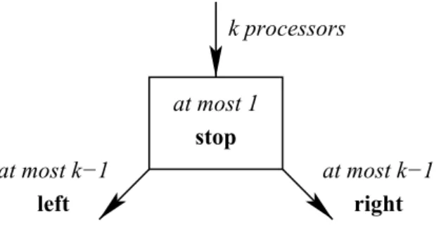
Definition 10.5 (Splitter) . A splitter is a synchronization primitive with the following characteristics. A node entering a splitter exits with either stop, left, or right. If k nodes enter a splitter, at most one node exits with stop and at most k − 1 nodes exit with left and right, respectively.
This definition guarantees that if a single node enters the splitter, then it obtains stop, and if two or more nodes enter the splitter, then there is at most one node obtaining stop and there are two nodes that obtain different values
4Be extra careful whenever such a word pops up. If it’s not indeed immediately obvious, it may translate to “I believe it works, but didn’t have the patience to check the details,” which is an excellent source of (occasionally serious) blunders. One of my lecturers once said: “If it’s trivial, then why don’t we write it down? It should not take more than a line. If it doesn’t, then it’s not trivial!”
Algorithm 23 Splitter Code
Shared Registers: X : {⊥} ∪ { 1, . . . , n } ; Y : boolean Initialization: X := ⊥ ; Y := false
Splitter access by node p
i:
1:
X := i;
2:
if Y then
3:
return right
4:
else
5:
Y := true
6:
if X = i then
7:
return stop
8:
else
9:
return left
10:
end if
11:
end if
10.3. STORE & COLLECT 137
Figure 10.1: A Splitter
(i.e., either there is exactly one stop or there is at least one left and at least one right). For an illustration, see Figure 10.1.
Lemma 10.6. Algorithm 23 implements a splitter.
Proof. Assume that k nodes enter the splitter. Because the first node that checks whether Y = true in line 2 will find that Y = false, not all nodes return right. Next, assume that i is the last node that sets X := i. If i does not return right, it will find X = i in Line 6 and therefore return stop. Hence, there is always a node that does not return left.
It remains to show that at most 1 node returns stop. Suppose p
idecides to do this at time t, i.e., p
ireads that X = i in Line 6 at time t. Then any p
jthat sets X := j after time t will (re)turn right , as already Y = true . As any other node p
jwill not read X = j after time t (there is no other way to change X to j), this shows that at most one node will return stop. Finally, observe that if k = 1, then the result for the single entering node will be stop.
10.3.2 Binary Splitter Tree
Assume that we are given 2
n− 1 splitters and that for every splitter S, there is an additional shared variable Z
S: {⊥} ∪ { 1, . . . , n } that is initialized to ⊥ and an additional shared variable M
S: boolean that is initialized to false. We call a splitter S marked if M
S= true. The 2
n− 1 splitters are arranged in a complete binary tree of height n − 1. Let S(v) be the splitter associated with a node v of the binary tree. The store and collect operations are given by Algorithm 24.
Theorem 10.7. Algorithm 24 implements store and collect . Let k be the number of participating nodes. The step complexity of the first store of a node p
iis O (k), the step complexity of every additional store of p
iis O (1), and the step complexity of collect is O (k).
Proof. Because at most one node can stop at a splitter, it is sufficient to show
that every node stops at some splitter at depth at most k − 1 ≤ n − 1 when
invoking the first store operation to prove correctness. We prove that at most
k − i nodes enter a subtree at depth i (i.e., a subtree where the root has distance
i to the root of the whole tree). This follows by induction from the definition
of splitters, as not all nodes entering a splitter can proceed to the same subtree
rooted at a child of the splitter. Hence, at the latest when reaching depth k − 1,
a node is the only node entering a splitter and thus obtains stop.
Algorithm 24 Adaptive collect: binary tree algorithm Operation store (val ) (by node p
i) :
1:
R
i:= val
2:
if first store operation by p
ithen
3:
v := root node of binary tree
4:
α := result of entering splitter S(v);
5:
M
S(v):= true
6:
while α 6 = stop do
7:
if α = left then
8:
v := left child of v
9:
else
10:
v := right child of v
11:
end if
12:
α := result of entering splitter S(v);
13:
M
S(v):= true
14:
end while
15:
Z
S(v):= i
16:
end if
Operation collect :
Traverse marked part of binary tree:
17:
for all marked splitters S do
18:
if Z
S6 = ⊥ then
19:
i := Z
S; f(p
i) := R
i// read value of node p
i 20:end if
21:
end for // f (p
i) = ⊥ for all other nodes
Note that the step complexity of executing a splitter is O (1). The bound of k − 1 on the depth of the accessed subtree of the binary splitter tree thus shows that the step complexity of the initial store is O (k) for each node, and each subsequent store requires only O (1) steps.
To show that the step complexity of collect is O (k), we first observe that the marked nodes of the binary tree are connected, and therefore can be traversed by only reading the variables M
Sassociated to them and their neighbors. Hence, showing that at most 2k − 1 nodes of the binary tree are marked is sufficient. Let x
kbe the maximum number of marked nodes in a tree when k ∈ N
0nodes access the root. We claim that x
k≤ max { 2k − 1, 0 } , which is trivial for k = 0. Now assume the inequality holds for 0, . . . , k − 1.
Splitters guarantee that neither all nodes turn left nor all nodes turn right, i.e., k
l≤ k − 1 nodes will turn left and k
r≤ min { k − k
l, k − 1 } turn right.
The left and right children of the root are the roots of their subtrees, hence the induction hypothesis yields
x
k≤ x
kl+ x
kr+ 1 ≤ max { 2k
l− 1, 0 } + max { 2k
r− 1, 0 } + 1 ≤ 2k − 1,
concluding induction and proof.
10.3. STORE & COLLECT 139
left right
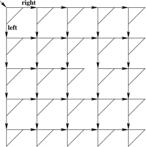
Figure 10.2: 5 × 5 Splitter Matrix
Remarks:
• The step complexities of Algorithm 24 are very good. Clearly, the step complexity of the collect operation is asymptotically optimal.
5In order for the algorithm to work, we however need to allocate the memory for the complete binary tree of depth n − 1. The space complexity of Algorithm 24 therefore is exponential in n. We will next see how to obtain a polynomial space complexity at the cost of a worse collect step complexity.
10.3.3 Splitter Matrix
In order to obtain quadratic memory consumption (instead of the exponential memory consumption of the splitter tree), we arrange n
2splitters in an n × n matrix as shown in Figure 10.2. The algorithm is analogous to Algorithm 24.
The matrix is entered at the top left. If a node receives left, it next visits the splitter in the next row of the same column. If a node receives right, it next visits the splitter in the next column of the same row. Clearly, the space complexity of this algorithm is O (n
2). The following theorem gives bounds on the step complexities of store and collect .
Theorem 10.8. Let k be the number of participating nodes. The step complexity of the first store of a node p
iis O (k), the step complexity of every additional store of p
iis O (1), and the step complexity of collect is O (k
2).
Proof. Let the top row be row 0 and the left-most column be column 0. Let x
ibe the number of nodes entering a splitter in row i. By induction on i, we show
5Here’s another clearly to watch carefully. While the statement is correct, it’s not obvious that we chose the performance measure wisely. We could refine our notion again and ask for the step complexity in terms of the number of writes that did not precede the most recent collectoperation of the collecting process. But let’s not go there today.