Quantum capacitance mediated carbon nanotube optomechanics
Stefan Blien 1 , Patrick Steger 1 , Niklas Hüttner 1 , Richard Graaf 1 & Andreas K. Hüttel 1,2 ✉
Cavity optomechanics allows the characterization of a vibration mode, its cooling and quantum manipulation using electromagnetic fields. Regarding nanomechanical as well as electronic properties, single wall carbon nanotubes are a prototypical experimental system.
At cryogenic temperatures, as high quality factor vibrational resonators, they display strong interaction between motion and single-electron tunneling. Here, we demonstrate large optomechanical coupling of a suspended carbon nanotube quantum dot and a microwave cavity, ampli fi ed by several orders of magnitude via the nonlinearity of Coulomb blockade.
From an optomechanically induced transparency (OMIT) experiment, we obtain a single photon coupling of up to g
0= 2 π ⋅ 95 Hz. This indicates that normal mode splitting and full optomechanical control of the carbon nanotube vibration in the quantum limit is reachable in the near future. Mechanical manipulation and characterization via the microwave fi eld can be complemented by the manifold physics of quantum-con fi ned single electron devices.
https://doi.org/10.1038/s41467-020-15433-3
OPEN
1Institute for Experimental and Applied Physics, University of Regensburg, 93040 Regensburg, Germany.2Present address: Department of Applied Physics, Aalto University, Puumiehenkuja 2, 02150 Espoo, Finland.✉email:andreas.huettel@ur.de
1234567890():,;
T he technically challenging integration of suspended single- wall cabon nanotubes into complex qantum devices has recently made significant advances1–6, as has also the integration of nanotube quantum dots into coplanar microwave cavities
7–9. Both regarding their nanomechanical
10,11 as well as their electronic properties
12,13, carbon nanotubes are a proto- typical experimental system. However, small vibrational deflec- tion and length have made their optomechanical coupling to microwave fields
14so far impossible.
In this work, we demonstrate large optomechanical coupling of a suspended carbon nanotube quantum dot and a microwave cavity. The nanotube is deposited onto source and drain elec- trodes close to the coplanar waveguide cavity; a finger-like extension of the cavity center conductor, passing below the sus- pended nanotube, serves as capacitively coupling gate. We find that the optomechanical coupling of the transversal nanotube vibration and the cavity mode is amplified by several orders of magnitude via the inherent nonlinearity of Coulomb blockade.
With this, full optomechanical control of the carbon nanotube vibration in the quantum limit
15is reachable in the near future. A unique experimental system becomes accessible, where the nanomechanically active part directly incorporates a quantum- confined electron system
16.
Results
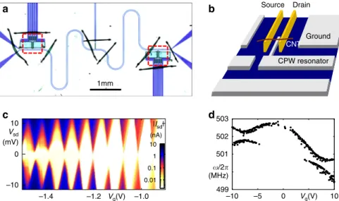
Device precharacterization. Our device, depicted in Fig. 1a, combines a half-wavelength coplanar microwave cavity with a suspended carbon nanotube quantum dot. Near the coupling capacitor, the center conductor of the niobium-based cavity is connected to a thin gate electrode, buried between source and drain contacts of the carbon nanotube, see the sketch of Fig. 1b.
At the cavity center, i.e., the location of the voltage node of its fundamental mode, a bias connection allows additional applica- tion of a dc voltage V
gto the gate. The device is mounted at the base temperature stage (T ≃ 10 mK) of a dilution refrigerator; for details see Supplementary Note 4 and Supplementary Fig. 4.
At cryogenic temperatures, electronic transport through the carbon nanotube is dominated by Coulomb blockade, with the typical behavior of a small band gap nanotube
12. Near the electronic band gap, sharp Coulomb oscillations of conductance can be resolved; measurements are shown in Fig. 1c and Supplementary Fig. 3. A well-known method to detect the transversal vibration resonance of a suspended nanotube quantum dot is to apply a rf signal and measure the time- averaged dc current
17–19. On resonance, the oscillating geometric capacitance, effectively broadening the Coulomb oscillations, leads to an easily recognizable change in current. This was used to identify the transversal vibration resonances of the device; Fig. 1d plots the resonance frequencies over a wide gate voltage range.
Two coupled vibration modes are observed (see also Supplemen- tary Note 5), one of which clearly displays electrostatic softening
20,21. At low gate voltages, ∣V
g∣ ≤ 1.2 V, where subse- quent experiments are carried out, the resonance which we will utilize in the following is at ω
m≃ 2π ⋅ 502.5 MHz, with typical quality factors around or exceeding Q
m~ 10
4observed in time- averaged dc current detection
17.
The combined suspended nanotube—cavity device forms a dispersively coupled optomechanical system
14. The cavity has a resonance frequency of ω
c= 2π ⋅ 5.74 GHz with a decay rate of κ
c= 2π ⋅ 11.6 MHz, dominated by internal losses. Nevertheless, due to the large mechanical resonance frequency ω
mof the carbon nanotube, the coupled system is far in the resolved sideband regime ω
m≫ κ
c, the most promising parameter region for a large number of optomechanical protocols including ground state cooling and quantum control.
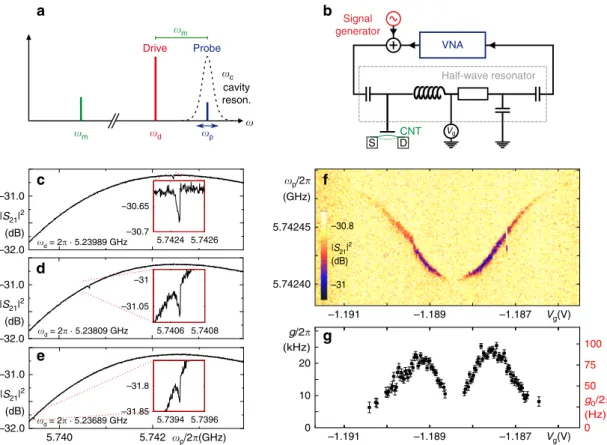
Optomechanically induced transparency (OMIT). To probe for optomechanical coupling, we perform an OMIT type experi- ment
22, cf. Fig. 2a, b: a strong, red-detuned drive field (ω
d≃ ω
c− ω
m) pumps the microwave cavity; the transmission of a weak, superimposed probe signal ω
pnear ω
cis detected. A distinct, sharp OMIT absorption feature within the transmission
b
1mm
a
10
0
–10
–1.4 –1.0
10 1 0.1 0.01 (nA)
|Isd|
c
Vg(V) Vsd
(mV)
d
499 501 502 503
–10 (MHz)
Vg(V) /2
CNT Ground Source
CPW resonator Drain
–1.2 –5 0 10
Fig. 1 Integrating a suspended carbon nanotube into a microwave cavity. aOptical micrograph showing a niobium-basedλ/2 coplanar waveguide cavity for transmission measurement, with carbon nanotube deposition areas and dc contact structures (see the red dashed squares) near the coupling capacitors. For fabrication redundancy, two deposition areas exist on the device, but only one is used here. Bond wires visible as dark lines connect different segments of the ground plane to avoid spurious resonances.bSimplified sketch of the nanotube deposition area, including source and drain electrodes, a carbon nanotube deposited on them, and the buried gate connected to the cavity center conductor.cdc transport characterization of the carbon nanotube atTbase≃10 mK. The plot of the absolute value of currrentj jI as function of gate voltageVgand bias voltageVsddisplays the typical diamond-shaped Coulomb blockade regions of suppressed conductance12,40,41.dUsing rf excitation with an antenna and dc measurement17,18, two transversal vibration modes can be traced across a large gate voltage range; thefigure plots the detected resonance frequencies. The corresponding raw data as well as afit can be found in Supplementary Figs. 6 and 7.
resonance of the cavity becomes visible in the measurements of Fig. 2c–e. It occurs due to destructive interference of the probe field with optomechanically upconverted photons of the drive field, when the two-photon resonance condition ω
p− ω
d= ω
mis fulfilled
22, and shifts in frequency as expected when ω
dis detuned from the precise red sideband condition, see Fig. 2d, e. Fitting the OMIT feature allows to extract the optomechanical coupling parameter g ¼ ffiffiffiffiffi
n
cp ð∂ω
c=∂xÞx
zpf, describing the cavity detuning per displacement of the mechanical harmonic oscillator
14,22, see Supplementary Note 9 for details. Surprisingly, from Fig. 2c, one obtains a single-photon coupling on the order of g
0¼
g= p ffiffiffiffiffi n
c2π 100 Hz.
Such a value of g
0strongly exceeds expectations from the device geometry
23. For a mechanical oscillator dispersively coupled to a coplanar waveguide resonator, the coupling is given by
g
0¼ ω
c2C
c∂C
c∂x x
zpf; ð1Þ
where C
cis the total capacitance of the cavity, x is the mechan- ical displacement, and x
zpfthe mechanical zero-point fluctua- tion length scale. Assuming a metallic wire over a metallic plane and inserting device parameters
23, the coupling calculated from the change in geometric gate capacitance C
g(x) becomes
∂C
g/∂x ~10
−12F m
−1. This leads to g
0¼ 2π 2:9 mHz, more than four orders of magnitude smaller than the measured g
0. To
explain this discrepancy, we need to focus on the properties of the carbon nanotube as a quantum dot, with a strongly varying quantum capacitance C
CNT(x) as the displacement-dependent component of C
cdominating g
0.
Figure 2f depicts OMIT measurements for similar parameters as in Fig. 2c–e, however, we now keep the drive frequency ω
dconstant and vary the gate voltage V
gacross a Coulomb oscillation of conductance. The mechanical resonance frequency ω
mshifts to lower frequencies in the vicinity of the charge degeneracy point. This electrostatic softening is a well-known characteristic of suspended carbon nanotube quantum dots
18,24. More interestingly, the resulting gate-dependent coupling g(V
g) (along with g
0(V
g)) is plotted in Fig. 2g. It is maximal at the edges of the finite conductance peak, whereas at its center and on the outer edges, the coupling vanishes; the enhancement of g
0is intrinsically related to Coulomb blockade.
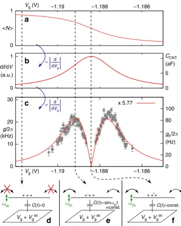
Mechanism of enhanced coupling. Figure 3 explores the nature of this enhanced coupling mechanism. We treat the nanotube as a single quantum dot; see Supplementary Note 3 for a discussion of the validity of this assumption. Further, we assume a full separation of time scales ω
m≪ ω
c≪ Γ, where Γ describes the tunnel rates of the quantum dot. We can then introduce the quantum capacitance
25,26C
CNT¼ e C
gC
dot∂hNi
∂V
g; ð2Þ
Signal generator
CNT VNA
Half-wave resonator
Vg
a
S D
b
5.74240 5.74245 (GHz)
20
10
0
50
0 –30.7
–30.65
5.7424 5.7426
–31.05 –31
5.7406
5.740 5.742
–31.85 –31.8
5.7394 5.7396
c
–32.0 –31.0
d
e
(dB)
|S21|2
–32.0 –31.0
(dB)
|S21|2
–32.0 –31.0
(dB)
|S21|2
–1.191 Vg(V)
–31 –30.8
(dB)
|S21|2
f
g
Probe Drive
cavity reson.
m
m d p
c
p/2(GHz)
p/2
g/2 (kHz)
g0/2 (Hz) d = 2 · 5.23989 GHz
d = 2 · 5.23809 GHz
d = 2 · 5.23689 GHz
75 100 5.7408
–1.187 –1.189
–1.191 –1.189 –1.187 Vg(V)
Fig. 2 Optomechanically induced transparency (OMIT) in the Coulomb blockade regime. aFrequency scheme andbdetection setup of an OMIT measurement. A strong drive signal atωd=ωc−ωmpumps the microwave cavity; the cavity transmission near the cavity resonanceωcis characterized using a superimposed weak probe signalωpfrom a vector network analyzer (VNA). Device parameters are:ωc≃2π⋅5.74 GHz,κc=2π⋅11.6 MHz,ωm≃ 2π⋅502.5 MHz.c–eProbe signal power transmissionjS21ðωpÞj2for three different choices of cavity drive frequencyωd, atωd=ωc−ωm(c) and slightly detuned (d,e). The gate voltageVg=−1.1855 V isfixed on theflank of a sharp Coulomb oscillation of conductance;Vsd=0.fProbe signal transmission as inc–e, now for afixed cavity drive frequencyωd=2π⋅5.23989 GHz and varied gate voltageVgacross a Coulomb oscillation. The depth of the OMIT feature allows the evaluation of the optomechanical couplingg(Vg) at each gate voltage value.gOptomechanical couplingg(Vg) (left axis) and corresponding single photon couplingg0ðVgÞ ¼gðVgÞ=pffiffiffiffiffinc(right axis), extracted from the data off;nc=67,500. Error bars indicate the standard error of thefit result.
where h iðV N
gÞ is the number of charge carriers (here holes) on the quantum dot averaged over the tunneling events, and C
dotis the total quantum dot capacitance; see Supplementary Note 12 for a derivation. In a quantum dot, each Coulomb oscillation corresponds to the addition of one electron or hole. The charge occupation h iðV N
gÞ resembles a step function, with the sharpness of the step given for zero bias voltage by lifetime and temperature broadening. This is plotted in Fig. 3a, for the limit of k
BT ≪ Γ.
The quantum capacitance C
CNT(V
g) becomes a Lorentzian, as plotted in Fig. 3b.
Any motion δx modulates the geometric capacitance C
g(x).
It thus shifts the position of the Coulomb oscillations in gate voltage, acting equivalent to an effective modulation of the gate voltage δV
g. With this, the optomechanical coupling g, scaling with j ∂C
CNT=∂x j, becomes proportional to the derivative
∂C
CNT/∂V
gand thus the second derivative of h iðV N
gÞ, as is illustrated in Fig. 3c. The functional dependence has been fitted to the data points of Fig. 2g, here again shown in the background.
The three key situations depending on the gate voltage are sketched in Fig. 3d–f: away from the conductance peak, the charge on the nanotube is constant, and only geometric capacitances change, see Fig. 3d. On the flank of the conductance
resonance, a small change δx (∝δC
g) strongly modulates C
CNT, see Fig. 3e. At the center of the conductance resonance, the charge adapts to x, but the derivative ∂C
CNT/∂V
gand with it g ∝ |∂C
CNT/
∂x| is approximately zero.
The detailed derivation and the full expressions and values for Fig. 3 can be found in the Supplementary Information, Sup- plementary Note 12, and Supplementary Table 1. The parameter entering the optomechanical coupling in Eq. (1), the derivative of the quantum capacitance ∂C
CNT/∂x, is found to be
∂C
CNT∂x ¼ η ∂C
g∂x ¼ e ∂
2h i N
∂V
2gV
gC
dot∂C
g∂x ; ð3Þ
indicating that for significant optomechanical coupling a sharp Coulomb oscillation (i.e., low temperature and low intrinsic line width Γ, leading to large values of ∂
2h i=∂V N
2g) and a large V
gare required. From device data, we obtain an amplification factor η ~ 10
4. The experimental gate voltage dependence g
0(V
g) is qualitatively reproduced very well. To obtain the quantitative agreement of Fig. 3c, we have introduced an additional scaling prefactor as free fit parameter, resulting in g
exp0=g
th0¼ 5:77. Given the uncertainties of input parameters, this is a good agreement;
see Supplementary Note 15 for a discussion of error sources.
Discussion
In literature, many approaches have been pursued to enhance optomechanical coupling
26–35. Resonant coupling, with ω
m= ω
c, has been demonstrated successfully for a carbon nanotube quantum dot
26, but does not provide access to the wide set of experimental protocols developed for the usual case of dispersive coupling and the “good cavity limit” ω
m≫ κ
c. The mechanism presented here is most closely related to those where a super- conducting charge qubit was coherently introduced between mechanical resonator and cavity
27. However, the impact of single electron tunneling and shot noise on the optomechanical system shall require careful analysis.
Given the sizeable coupling in the good cavity limit κ
c≪ ω
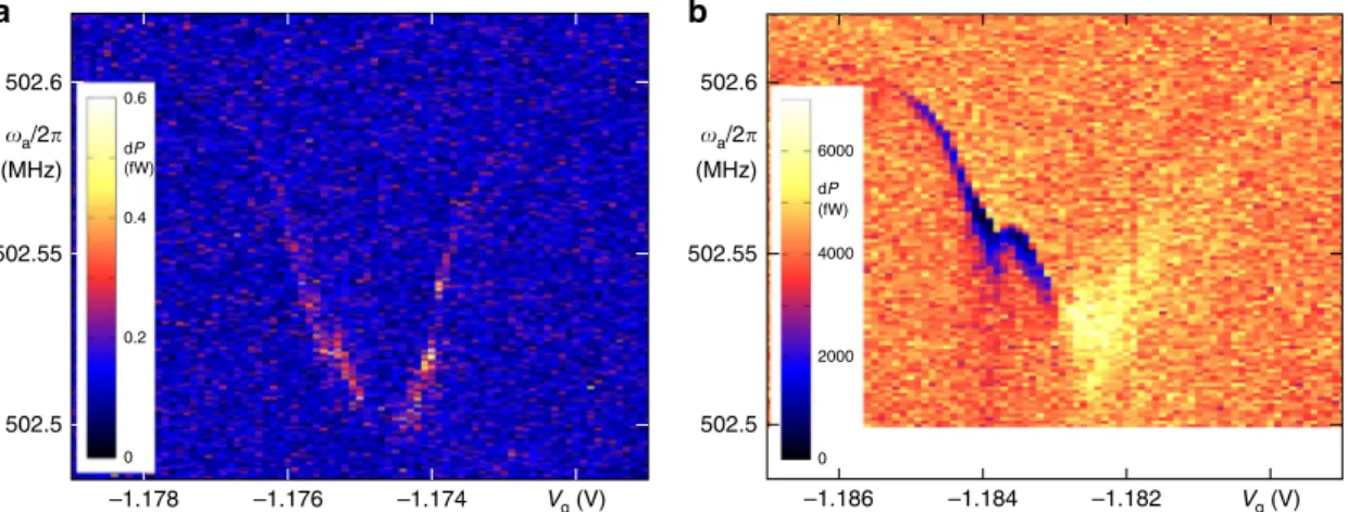
m, many experimental techniques for future experiments are at hand. First steps are demonstrated in Fig. 4 in a two-tone spec- troscopy experiment: a mechanical drive signal ω
ais applied simultaneously to a cavity pump signal at ω
d= ω
c− ω
a; the plotted cavity output power at ω
cclearly shows the optmechanical upconversion (anti-Stokes scattering) at mechanical resonance ω
a= ω
m. In Fig. 4a, the dc bias across the nanotube is set to zero, and the antenna drive kept at a minimum. In Fig. 4b, both antenna drive and bias voltage have been increased. A back- ground signal independent of device parameters emerges; at the same time, the upconverted signal displays a phase shift and destructive interference with the background for parts of the gate voltage range, meriting further measurements and analysis.
Future improvements of the optomechanical coupling via drive power and device geometry and of the detection sensitivity via the output amplifier chain shall allow detection of the thermal motion of the carbon nanotube and subsequently motion amplitude calibration.
The observation of strong optomechanical coupling and the corresponding normal mode splitting requires a coupling g exceeding both mechanichal linewidth κ
mand cavity line width κ
c. Clean carbon nanotubes have reached mechanical quality factors up to
36Q
m~ 10
6, allowing for two orders of magnitude improvement and a line width of κ
m~ 2π · 500 Hz.
Regarding microwave resonators we have reached up to Q
c= 10
5in our setup so far, corresponding to κ
c= 2π · 57 kHz. This means that strong coupling should be reachable already at moderate increase of our so far rather low cavity photon number n
c.
0 1
0 1
0 5
0
+ + + + ++ + + + ++
10 20
0 20 80 g/2
(kHz) dI/dV (a.u.)
<N>
CCNT (aF)
C(t)≈0 C(t)∝sinmt C(t)≈const.
m m +const. m
–1.19 Vg (V)
a
b
c
f
g0/2 (Hz) 30
100
∝ d
∝ dVg
d dVg
x 5.77 –1.186 –1.188
–1.19 Vg (V)
Vg + Vgac Vg + Vgac Vg + Vgac –1.186 –1.188
e d
Fig. 3 Coulomb blockade enhanced optomechanical coupling mechanism.
Solid lines correspond to the model of a Lorentz-broadened quantum dot level atkBT≪Γ. The Coulomb oscillation centerVg¼ 1:18841V, the line widthℏΓ=0.673 meV, and a scaling prefactora=5.77 (see text) have been obtained byfitting to the OMIT datag(Vg).aTime-averaged charge occupationh iðN VgÞof the quantum dot (note that we are in the hole conduction regime).bConductance dI/dVsd(Vg) (left axis) and quantum capacitanceCCNT(right axis), cf. Supplementary Fig. 12.cCoulomb- blockade enhanced optomechanical couplingg(Vg) (left axis) and single photon couplingg0(Vg) (right axis). The data points are identical to Fig.2g; the calculation result has been scaled with 5.77 tofit the data.
d–fSchemata for the situations corresponding to the dashed lines ina–c, see the text.
Regarding the cooperativity C = 0.0042 of our experiment (cf.
Supplementary Table 1), already an improvement of the nano- tube Q
mby a factor 100 brings it into the same order of mag- nitude as the thermal mode occupation n
m= 0.4, with significant further and independent room for improvement via the cavity photon number n
c.
With this, a wide range of physical phenomena becomes experimentally accessible, ranging from side-band cooling of the vibration mode and potentially its quantum control
37all the way to real-time observation of its interaction with single electron tunneling phenomena
38.
Data availability
The datasets generated during and/or analyzed during this study are available from the corresponding author on reasonable request.
Received: 18 July 2019; Accepted: 11 March 2020;
References
1. Wu, C. C., Liu, C. H. & Zhong, Z. One-step direct transfer of pristine single- walled carbon nanotubes for functional nanoelectronics.Nano Lett.10, 1032–1036 (2010).
2. Pei, F., Laird, E. A., Steele, G. A. & Kouwenhoven, L. P. Valley-spin blockade and spin resonance in carbon nanotubes.Nat. Nanotechnol.7, 630–634 (2012).
3. Ranjan, V. et al. Clean carbon nanotubes coupled to superconducting impedance-matching circuits.Nat. Commun.6, 7165 (2015).
4. Gramich, J., Baumgartner, A., Muoth, M., Hierold, C. & Schönenberger, C.
Fork stamping of pristine carbon nanotubes onto ferromagnetic contacts for spin-valve devices.Phys. Stat. Solidi B252, 2496–2502 (2015).
5. Waissman, J. et al. Realization of pristine and locally tunable one-dimensional electron systems in carbon nanotubes.Nat. Nanotechnol.8, 569–574 (2013).
6. Blien, S., Steger, P., Albang, A., Paradiso, N. & Hüttel, A. K. Quartz tuning- fork based carbon nanotube transfer into quantum device geometries.Phys.
Stat. Solidi B255, 1800118 (2018).
7. Delbecq, M. R. et al. Photon-mediated interaction between distant quantum dot circuits.Nat. Commun.4, 1400 (2013).
8. Viennot, J. J., Dartiailh, M. C., Cottet, A. & Kontos, T. Coherent coupling of a single spin to microwave cavity photons.Science349, 408–411 (2015).
9. Cubaynes, T. et al. Highly coherent spin states in carbon nanotubes coupled to cavity photons.npj Quant. Inf.5, 47 (2019).
10. Witkamp, B., Poot, M. & van der Zant, H. Bending-mode vibration of a suspended nanotube resonator.Nano Lett.6, 2904-2908 (2006).
11. Sazonova, V. et al. A tunable carbon nanotube electromechanical oscillator.
Nature431, 284–287 (2004).
12. Laird, E. A. et al. Quantum transport in carbon nanotubes.Rev. Mod. Phys.87, 703–764 (2015).
13. Margańska, M. et al. Shaping electron wave functions in a carbon nanotube with a parallel magneticfield.Phys. Rev. Lett.122, 086802 (2019).
14. Aspelmeyer, M., Kippenberg, T. J. & Marquardt, F. Cavity optomechanics.
Rev. Mod. Phys.86, 1391–1452 (2014).
15. Poot, M. & van der Zant, H. S. J. Mechanical systems in the quantum regime.
Phys. Rep.511, 273–335 (2012).
16. Weig, E. M. et al. Single-electron-phonon interaction in a suspended quantum dot phonon cavity.Phys. Rev. Lett.92, 046804 (2004).
17. Hüttel, A. K. et al. Carbon nanotubes as ultrahigh quality factor mechanical resonators.Nano Lett.9, 2547–2552 (2009).
18. Steele, G. A. et al. Strong coupling between single-electron tunneling and nanomechanical motion.Science325, 1103–1107 (2009).
19. Götz, K. J. G. et al. Nanomechanical characterization of the Kondo charge dynamics in a carbon nanotube.Phys. Rev. Lett.120, 246802 (2018).
20. Wu, C. C. & Zhong, Z. Capacitive spring softening in single-walled carbon nanotube nanoelectromechanical resonators.Nano Lett.11, 1448–1451 (2011).
21. Stiller, P. L., Kugler, S., Schmid, D. R., Strunk, C. & Hüttel, A. K. Negative frequency tuning of a carbon nanotube nano-electromechanical resonator under tension.Phys. Stat. Solidi B250, 2518–2522 (2013).
22. Weis, S. et al. Optomechanically induced transparency.Science330, 1520–1523 (2010).
23. Regal, C. A., Teufel, J. D. & Lehnert, K. W. Measuring nanomechanical motion with a microwave cavity interferometer.Nat. Phys.4, 555–560 (2008).
24. Lassagne, B., Tarakanov, Y., Kinaret, J., Garcia-Sanchez, D. & Bachtold, A.
Coupling mechanics to charge transport in carbon nanotube mechanical resonators.Science325, 1107–1110 (2009).
25. Duty, T. et al. Observation of quantum capacitance in the Cooper-pair transistor.Phys. Rev. Lett.95, 206807 (2005).
26. Ares, N. et al. Resonant optomechanics with a vibrating carbon nanotube and a radio-frequency cavity.Phys. Rev. Lett.117, 170801 (2016).
27. Pirkkalainen, J.-M. et al. Hybrid circuit cavity quantum electrodynamics with a micromechanical resonator.Nature494, 211–215 (2013).
28. Rimberg, A. J., Blencowe, M. P., Armour, A. D. & Nation, P. D. A cavity- Cooper pair transistor scheme for investigating quantum optomechanics in the ultra-strong coupling regime.New J. Phys.16, 055008 (2014).
29. Heikkilä, T. T., Massel, F., Tuorila, J., Khan, R. & Sillanpää, M. A. Enhancing optomechanical coupling via the Josephson effect.Phys. Rev. Lett.112, 203603 (2014).
30. Abdi, M., Pernpeintner, M., Gross, R., Huebl, H. & Hartmann, M. J. Quantum state engineering with circuit electromechanical three-body interactions.Phys.
Rev. Lett.114, 173602 (2015).
31. Lecocq, F., Teufel, J. D., Aumentado, J. & Simmonds, R. W. Resolving the vacuumfluctuations of an optomechanical system using an artificial atom.
Nat. Phys.11, 635–639 (2015).
32. Pirkkalainen, J.-M. et al. Cavity optomechanics mediated by a quantum two- level system.Nat. Commun.6, 6981 (2015).
33. Xue, Z.-Y., Yang, L.-N. & Zhou, J. Circuit electromechanics with single photon strong coupling.Appl. Phys. Lett.107, 023102 (2015).
0 0.2 0.4 0.6
502.5 502.55 502.6
0 2000 4000 dP 6000
(fW)
dP (fW)
(MHz)
–1.178 Vg (V) –1.186 Vg (V)
a b
a/2
502.5 502.55 502.6
(MHz) a/2
–1.182 –1.184
–1.174 –1.176
Fig. 4 Two-tone spectroscopy.Via an antenna, the carbon nanotube is driven atωaclose its mechanical eigenfrequency; the microwave cavity is simultaneously pumped atωd=ωc−ωa. The plots show the power output of the cavity at the upconverted frequencyωc, with the nanotube acting as nonlinear element. Drive powerPd=20 dBm (nc≃2.1 × 10⁴), measurement bandwidth 5 Hz.aAntenna generator powerPa=−55 dBm, biasVsd=0;
bantenna generator powerPa=−30 dBm, biasVsd=0.5 mV.
34. Santos, J. T., Li, J., Ilves, J., Ockeloen-Korppi, C. F. & Sillanpää, M.
Optomechanical measurement of a millimeter-sized mechanical oscillator approaching the quantum ground state.New J. Phys.19, 103014 (2017).
35. Shevchuk, O., Steele, G. A. & Blanter, Y. M. Strong and tunable couplings in flux-mediated optomechanics.Phys. Rev. B96, 014508 (2017).
36. Moser, J., Eichler, A., Güttinger, J., Dykman, M. I. & Bachtold, A. Nanotube mechanical resonators with quality factors of up to 5 million.Nat.
Nanotechnol.9, 1007–1011 (2014).
37. O’Connell, A. D. et al. Quantum ground state and single-phonon control of a mechanical resonator.Nature464, 697–703 (2010).
38. Barnard, A. W., Zhang, M., Wiederhecker, G. S., Lipson, M. & McEuen, P. L.
Real-time vibrations of a carbon nanotube.Nature566, 89–93 (2019).
39. Reinhardt, S. et al. Lab::Measurement—a portable and extensible framework for controlling lab equipment and conducting measurements.Comput. Phys.
Commun.234, 216–222 (2019).
40. Kouwenhoven, L. P. et al. Electron Transport in Quantum Dots(Kluwer, 1997).
41. Nazarov, Y. V. & Blanter, Y. M.Quantum Transport: Introduction to Nanoscience(Cambridge University Press, Cambridge, 2009).
Acknowledgements
The authors acknowledge funding by the Deutsche Forschungsgemeinschaft via Emmy Noether grant Hu 1808/1, SFB 631, SFB 689, SFB 1277, and GRK 1570. We would like to thank G. Rastelli, F. Marquardt, E. A. Laird, Y. M. Blanter, and D. Weiss for insightful discussions, O. Vavra for experimental help, and Ch. Strunk and D. Weiss for the use of the experimental facilities. The data have been recorded using Lab::Measurement39.
Author contributions
A.K.H. and S.B. conceived and designed the experiment. P.S. and R.G. developed and performed the nanotube growth and transfer; N.H. and S.B. developed and fabricated the coplanar waveguide device. The low temperature measurements were performed jointly by all authors. Data evaluation and writing of the paper was done jointly by S.B., N.H., and A.K.H. The project was supervised by A.K.H.
Competing interests
The authors declare no competing interests.
Additional information
Supplementary informationis available for this paper athttps://doi.org/10.1038/s41467- 020-15433-3.
Correspondenceand requests for materials should be addressed to A.K.Hüt.
Peer review informationNature Communicationsthanks Joel Moser and the other anonymous reviewer(s) for their contribution to the peer review of this work.
Reprints and permission informationis available athttp://www.nature.com/reprints
Publisher’s noteSpringer Nature remains neutral with regard to jurisdictional claims in published maps and institutional affiliations.
Open Access This article is licensed under a Creative Commons Attribution 4.0 International License, which permits use, sharing, adaptation, distribution and reproduction in any medium or format, as long as you give appropriate credit to the original author(s) and the source, provide a link to the Creative Commons license, and indicate if changes were made. The images or other third party material in this article are included in the article’s Creative Commons license, unless indicated otherwise in a credit line to the material. If material is not included in the article’s Creative Commons license and your intended use is not permitted by statutory regulation or exceeds the permitted use, you will need to obtain permission directly from the copyright holder. To view a copy of this license, visithttp://creativecommons.org/
licenses/by/4.0/.
© The Author(s) 2020