Edited by Frank Vollertsen
Available online at https://elib.suub.uni-bremen.de www.drymetalforming.de
Dry Met. Forming OAJ FPR 6 (2020) 099–127 Date of Report 31 May 2020; published 12 June 2020
© 2020 The Authors. Published under responsibility of BIAS - Bremer Institut für angewandte Strahltechnik GmbH.
*E-mail address of corresponding author: flegler@ptu.tu-darmstadt.de
Dry Metal Forming Open Access Journal
Final Project Report
Dry forming of aluminum
(DFG Grant No. GR1818/52&66; BR 2178/28&44 Funding Period 01.01.2014 – 31.05.2020)
Felix Flegler1, Peter Groche1, Tim Abraham2, Günther Bräuer2
1Institute for Production Engineering and Forming Machines, Otto-Berndt-Straße 2, 64287 Darmstadt
2Fraunhofer Institute or Surface Engineering and Thin Films IST, Bienroder Weg 54 E, 38108 Braunschweig, Germany
Summary
Aluminum parts are used in a wide range of applications. However, the strong adhesion of aluminum to nu- merous tool materials is challenging for production processes. To ensure an economic production of aluminum sheet parts a high quantity of lubricants is currently needed. The additional process steps and operating re-sources associated with their use considerably reduce the sustainability of production.
Ecological advantages achieved by lightweight construction during the use phase of aluminum products lose their value drastically when the entire life cycle is considered. The aim of the research project is therefore the development, qualifi-cation and transfer of a surface technology system solution for the optimization of tools, whereby the use of lubricants is dispensed with and an environmentally friendly production of aluminum parts is achieved.
Within the scope of the research project, the basic wear mechanisms during the lubricant-free forming of alu- minum sheets were investigated and strategies for industrial implementation were explored. Starting point of the investigations was a holistic view of the tribological system. In addition to process-driven variables such as contact normal stress and temperature, a significant influence of the semi-finished product in terms of sur- face chemistry and topography was found. The inert and particularly smooth design of the tribological contact plays a decisive role in this respect. On the sheet side, the native aluminum oxide layer ensures a separation of the reactive aluminum matrix and its performance was improved by additional electrolytic treatment. Further-more, the adhesive wear was significantly reduced by providing sheet material with a high proportion of ma-terial close to the surface. On the tool side, amorphous hydrogenated carbon (a-C:H) caotings were deposited to provide an inert surface. In order to additionally create a nanoscopic smooth tool surface economically, different action strategies along the process chain for tool production were investigated. In addition to various approaches for optimizing the coating process, these strategies consist of a roughness-oriented material selec-tion and different polishing processes that are variable in the process sequence. All investigations were based on a sequential qualification method (tribometer, strip drawing, application) in order to narrow down the scope of solutions for application tests. Finally, the mechanical- chemical polishing of a-C:H coated forming tools was qualified for industrial application in deep-drawing tests.
Keywords: Metal forming, Tribology, Aluminum
1 Motivation
Aluminum is an excellent material for a wide range of applications especially in the automotive and aerospace industry due to its weight advantage and excellent energy absorption capacity. However, the high adhesion tendency of aluminum to numerous materials complicates the design and procedure of forming processes. To
ensure a good component quality and stable processes a high amount of lubricants is currently required to prevent a formation of aluminum adhesions on the tool surface [1]. With respect to the global attempt to reduce the CO2 emissions, this tribological issue describes a conflict between the ecological and economical goals for optimizing metal forming processes. On the one hand, lightweight constructions are used to manufacture prod- ucts that have less impact on the environment during the use phase. On the other hand, the use of lubricants significantly reduces the sustainability of the production process. Not only the production of the lubricant has to be considered, but also the associated process steps and operating materials as well as the treatment and disposal of the lubricants.
In case of metal forming processes, the environmental impact of lubricants is rarely analyzed. There are only a few studies for incremental forming [2] and massive forming applications [3] with a focus on the energy consumption including the preliminary material production and the forming process itself, but the ecological influences of lubricants are not considered. However, extensive life cycle assessments are available for ma- chining processes reporting in general a negative impact of lubricants on the sustainability of production pro- cesses [4–6]. For this reason, numerous investigations were conducted to find new strategies for improving the eco-balance. One favored solution is the reduction of the lubricant amount also known as minimum quantity lubrication (MQL) [7]. Another approach is the replacement of the base fluid by bio-based and degradable fluids [8] or the integration of bio-based additives like chitosan [9] or microbes[10]. Also the recycling of used lubricating oils [11] or the usage of a single lubricant along the process chain in preliminary or following production systems [12] possess a high potential to lower the environmental impact. Nevertheless, most of the lubricants used for sheet metal forming applications are based on crude or synthetic oil. Furthermore, the pro- cess chain in sheet metal forming often includes a subsequent cleaning of the formed metal sheets for example to ensure a good adhesion of a lacquer coat or to prevent a contamination of other contacting materials. Lub- ricants account for this additional process or at least complicates the cleaning method. A sophisticated life cycle assessment of metal forming applications has to consider these negative factors, which worsen the envi- ronmental impact of lubricants on manufacturing processes significantly.
The utilization of dry sheet metal forming is a capable approach to improve the sustainability of aluminum products. However, forgoing the usage of lubricants leads to a rapid formation of aluminum adhesions on the tool surface and often to an immediate tool failure. By considering the relevant wear mechanisms and influ- encing parameters, effective strategies need to be developed for improving the tribological conditions in a dry contact with aluminum.
2 Scientific Objective
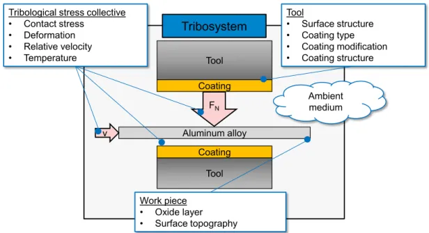
For the development of suitable tribosystems for dry forming of aluminum alloys, fundamentally effective mechanisms of adhesive wear formation must first be investigated. The first goal of the research project is therefore the identification of the relevant adhesion mechanisms during dry forming of technically and indus- trially relevant aluminum alloys. For a targeted investigation it has proved necessary to consider almost the complete tribological system, since many influencing factors cannot be considered in isolation. Measures for the realization of dry forming should be derived from the individual investigation results. In the course of the project promising measures were prioritized and extended. The different influencing variables on the adhesion behavior are divided into four categories and are exemplarily shown in Figure 1. The tribological stress col- lective describes the tribological quantities applied by the forming process. In the deep-drawing process, the acting contact normal stress results mainly from the applied blankholder force and the material strength. It is often not a direct influencing variable, but is driven by the process to be implemented and the subsequent application of the manufactured components. According to literature [Source Archard], the contact normal stress has a direct influence on the wear behavior. Therefore, it should also be investigated whether the contact normal stress can be reduced by a load-optimized tool design. A further possibility to reduce the load on the process side is already being used today for complex parts with limited formability. The complexity of com- ponents can be significantly increased by splitting them into several forming stages. In the context of the in- vestigation presented here, the question should therefore be clarified whether a separation into several stages with the same final result is capable of reducing the tribological loads, especially with regard to the normal contact stress. The productivity of forming processes is mainly defined by the frequency of the press stroke.
This results directly in the corresponding relative speeds in the tribological contact. In the lubricated case, the relative speed usually has a great influence on the coefficients of friction and, accordingly, the forming result.
The extent to which this influence also applies to dry forming is also being investigated. In addition to the friction already mentioned, heat is also generated in the forming process by the forming work performed in the
material structure, which is why the temperature in tribological contact is a complex variable. Especially with regard to the wear behavior, the temperature seems to play a decisive role, since preliminary investigations have shown that an optimum temperature exists with regard to the wear at dry friction of aluminum against steel [13]. The aim is to investigate whether a suitable temperature control can promote dry forming and pre- vent wear. In addition to the influencing variables on the process side, it is also possible to influence the wear behavior via the tool and semi-finished product, in this case aluminum sheet. In addition to the alloying ele- ments, which decisively determine the mechanical properties, the surface topography is also of elementary importance in dry friction [14].
Figure 1 Influencing variables on the dry forming process with the most comprehensive coverage of the tribological system possible
The topographies typical for lubricated sheet metal forming, such as mill-finish and EDT, have been optimized mainly with regard to interaction with lubricants and promote hydrodynamic effects and improve lubricant adhesion on the surface [15]. Whether topography optimization with regard to dry forming is necessary is to be clarified in the following. The function of the lubricant or a coating is first of all to separate the friction partners by means of an anti-adhesive intermediate material. When in contact with atmospheric oxygen, alu- minum forms a natural oxide layer consisting of AlOx, which initially increases the resistance to corrosive processes due to its inert properties [16]. These inert properties are also noticeable in the susceptibility to wear:
While the tendency to form adhesions is very high for the aluminum matrix, aluminum oxide cannot be con- sidered to have a significant tendency to adhere to steel [16]. During forming, however, both micro- and mac- roscopic strains occur in the material. The hard and brittle oxide layer fails in advance of the base material due to its very limited formability, which is why the damage exposes the adhesive substrate and results in aluminum adhesion to the tool. Within the scope of the work presented here, it is to be shown that dry forming seems to be possible by a specific manipulation of the aluminum oxide layer. After completion of the investigation of the individual influencing factors, those which have the greatest potential to make dry forming possible will be selected. Taking into account the findings obtained, a rotationally symmetrical cup is deep-drawn. The lubricated reference case and the solution found for dry forming are compared. From this, design and action recommendations for the forming process to be realized can be derived. In the following sections, the materials used for tools and workpieces are presented first. This is followed by a presentation of the experimental meth- odology for iterative solution finding, sample preparation and cleaning to ensure dry experimental properties.
After the presentation of the equipment used, the investigated solution approaches and influencing variables are presented. Finally, a critical examination of the found solutions and a classification into the superordinate vision of dry forming is given.
3 Materials and Methods
The following chapter gives an overview of the materials used. To keep the experimental matrix as efficient as possible, reference materials for tool and workpiece were defined at the beginning of the project. Apart from these materials, other materials were tested with regard to their adhesion tendency on both the tool and the workpiece side. This will be discussed at the corresponding place.
Aluminum alloy Tool Coating
Tool Coating
Ambient medium Tool
• Surface structure
• Coating type
• Coating modification
• Coating structure
Work piece
• Oxide layer
• Surface topography Tribological stress collective
• Contact stress
• Deformation
• Relative velocity
• Temperature
v
FN
Tribosystem
3.1 Tool material and test substrates
In accordance with the agreements made at the beginning of the priority program, the tool material with the material number 1.2379 was used. This is a ledeburitic steel, which is also known by the short name X153CrMoV12. The chemical composition (Table 1) has a comparatively high chromium and carbide content, which ensures good corrosion resistance and very good resistance to adhesive and abrasive wear.
Table 1: Chemical composition of cold work steel in % [17,18]
C Cr Si Mn Mo V Fe
1.2379 1.55 12.0 0.8 0.9 rest
Vanadis 4 Extra Clean 1.4 4.7 0.4 0.4 3.5 3.7 rest
The material is often used for cutting and punching tools as well as for extrusion, bending and deep-drawing tools. Furthermore, the material is often used as a base material for subsequent nitriding or various coating processes (CVD, PVD, and PACVD). The mechanical material properties result in a modulus of elasticity E of 210 GPa and a 0.2% yield strength of about 423 MPa [17]. During the investigations the existence of carbide precipitations was identified as one crucial factor influencing the achievable surface quality of forming tools.
Hence, the powder metallurgical cold work steel Vanadis 4 Extra Clean [18] was additionally used which excels with a smaller precipitations and a higher polishing grade. For a quality assurance of the coating pro- cesses and the ball-on-sheet tribometer tests (see Section 4.2), the bearing steel 1.3505 was used.
All substrates were standard polished with 3 µm diamond suspension as finish. Furthermore, before testing and coating the substrates were cleaned according to [19] using isopropanol, acetone and ethanol as cleaning agent to guarantee a lubricant, grease and particle free surface.
3.2 Work piece material
The wear behavior during dry forming is carried out within the scope of this project using the sheet metal material EN AW-5083. This is an aluminum alloy also known as AlMg4.5Mn and material number 3.3547.
The percentages by mass of the alloy components are listed in Table 2. Due to the chemical composition of the alloy, this is a non-age-hardenable, naturally hard aluminum alloy. During forming of this material, hard- ening mechanisms in the form of solid solution hardening and work hardening therefore occur, flow figures are observed [20].
Table 2 Chemical composition of EN AW-5083 in % [21]
Si Fe Cu Mn Mg Cr Zn Ti Al
0,4 0,4 0,1 0,4 - 1,0 4,0 - 4,9 0,05 - 0,25 0,25 0,15 other
Compared to steel sheets, aluminum alloys have comparatively poor forming properties, which is due to their low elongation at break and high anisotropy [22]. The elongation at break for EN AW-5083 is 12-16 % [21].
Tensile tests along the rolling direction also yield a tensile strength of about 280 MPa and a 0.2% yield strength of 150 MPa. Due to the strong anisotropy of the rolled sheet material, a reduction of the mechanical material properties perpendicular to the rolling direction is to be expected. The material was defined as a standard material in the priority program due to its good availability.
Figure 2: Topography of a mill-finish surface
The material thickness of the metal blanks is 1.5 mm. While a width of 250 mm is required for deep drawing in the production of blanks, 50 mm wide sheet metal strips are used in the strip drawing test. The surface texturing of the sheet metal samples used consists of a mill-finish surface which is the standard for this and many other alloys. Figure 2 shows the surface texture of the sheet material. The structure applied during the manufacturing process as well as the rolling direction can be clearly seen. Due to the irregular scoring in the surface, it is difficult to determine an exact roughness value. For our own measurements, however, this is usually between Ra = 0.4 ... 1.0 μm or Rz = 3 ... 8 μm.
4 Machines 4.1 Coating plants
According to the specification of the coating system to be deposited and its subsequent treatment, three differ- ent coating systems are used, see Table 3. The BAS PM 450 from Balzers combines magnetron sputtering (PVD) and PACVD technologies and enables the deposition of a-C:H layer systems with metallic adhesive and top layers. Various substrate holders can be attached to a motor mounted in the lid via an M10 thread and their positioning can be controlled with a single rotation. The size of the substrate holders used depends on the space required, whereby either one or two holders can be mounted. The BAS PM 450 magnetron sputtering system forms the basis for the deposition of the referential a-C:H coating system and the subsequent coating development for the application of a running-in layer in Section 5.2.4. The DLCarbon 550 and DLCarbon 150 are pure PACVD systems based on a design developed by Fraunhofer IST. The substrate holders in both coat- ing systems are plates attached to the bottom of the systems on which the test specimens and tools are placed.
The DLCarbon 550 PACVD laboratory system is used for the development of silicon- and fluorine-modified a-C:H coatings in Section 5.2.3 and the deposition of smooth a-C:H coating systems in Section 5.2.5. The DLCarbon 150 is used for plasma-assisted etching of the referential a-C:H coating system in Section 5.2.5.
Table 3: Specifications of the PVD/PACVD coating systems
BAS PM450 DLCarbon 550 DLCarbon 150
Type PVD/ PACVD PVD PVD
Chamber size mm Ø 450 x 500 410 x 450 x 750 Ø 500 x 345
Substrate holder mm variable Ø 300 Ø 400
Target stimulation DC - -
Substrate stimulation DC/ RF RF RF
Target power supply kW < 10 - -
Substrate power supply kW < 1 < 1.5 < 1
Basic pressure mbar < 10-6 < 10-6 < 10-6
Available target slots 2 - -
4.2 Tribometers
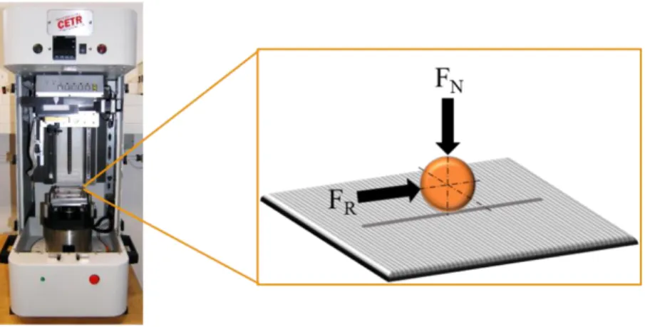
Oscillating ball-on-sheet tribometer tests are carried out for an initial evaluation of the tribological conditions using an Universal Mechanical Tester 3 (UMT3) from Bruker. In this setup the ball replaces the deep-drawing tool, which slides against aluminum sheets, see Figure 3. The tester has extensive adjustment possibilities with regard to the surrounding media, movement forms and test parameters.
Figure 3: Oscillating Ball-on-sheet tribometer test us an Universal Mechanical Tester 3 (UMT3)
The oscillating motion can be extended by a transversal offset of the ball holder, whereby serrated friction paths are also possible. In addition, the data acquisition rate (here 3 kHz) and the derivation of the Coefficient
of Friction (CoF) can be freely selected. The tests take place in a climatically controlled environment, which offers possibilities for a specific adjustment of the relative humidity and gas composition. The initial contact pressure (FN) corresponds to the load at the drawing ring radius of a forming tool. However, as the measuring distance increases, the contact area widens due to wear and deformation of the contact surface leading to a reduced contact pressure. Thus, test condition resembles with increasing sliding distance more and more the load spectrum of the flange area of forming tools. The test parameters are derived from the load spectrum within the deep-drawing die and are listed in Table 4.
Table 4: Parameters used for the ball-on-sheet tribometer tests
Value
Ball diameter mm 10
Normal force N 4
Initial contact pressure MPa 480
Stroke length mm 20
Velocity mms-1 50
Relative humidity % 40 ± 5
Temperature °C 22 ± 1
For the investigation of wear properties and other tribological conditions in sheet metal forming, the combined strip drawing test stand of the PtU is used in this work (Figure left). By means of the strip drawing test, certain tribological situations of a deep drawing process can be modelled. A hydraulically controlled blank holder applies a normal force to a sheet metal strip clamped between two dies. A gripper, which is driven by a rotating eccentric disc, provides the necessary relative movement between the friction bodies. The system is equipped with precise force measurement technology, which can be used to absorb tensile and normal forces.
Figure 4: Combined strip drawing unit (left) and strip drawing tools (right)
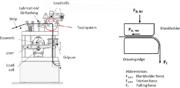
Different tool geometries are used depending on the test mode. While the cylinder-plane tests simulate the tribological conditions in the forming zone of the deep drawing process both in the plane flange area and at the drawing edge, drawing bead tools are used to additionally take into account the multiple bends during sheet metal forming (Figure 4 right). Due to the dry forming to be investigated, the existing periphery for cleaning and controlled oiling of the sheet metal is not used in this work. The combined strip drawing unit allows the investigation of sheet metal strips with a width between 30 and 50 mm and a sheet thickness between 0.5 and 2.5 mm. The drawing speed is continuously adjustable up to a maximum of 100 mm/s. Due to the exact ad- justability of individual test parameters such as surface pressure, speed and tool configuration, the strip draw- ing test on the combined strip drawing test stand is very well suited for basic research under realistic conditions [23]. The intermittent strip drawing unit (Figure ) serves as a further substitute test for the deep drawing pro- cess. Due to the angled design between sheet feeding and gripper, this test stand is particularly suitable for investigating the friction conditions at the drawing radius. A tool with a defined drawing edge and a blank holder are screwed into the system and a 20 mm wide sheet metal strip is inserted. The sheet metal strip is first cleaned with acetone, deburred and bent over the tool. Then the strip is pulled down by several rollers and guided into a pneumatic gripper. This gripper grips the sheet metal under pressure and then pulls the sheet metal down over the tool by the specified stroke length of 25mm. The gripper is moved by a rotating eccentric shaft, which can be activated with a switch.
Figure 5: Left: Design of the strip drawing test stand. Right: Tool system with blank holder
On the machine it is possible to adjust the blankholder force and the drawing speed. The possible surface pressure in the blankholder area is between 1 - 50 N/mm² and the drawing speed has its maximum at 200mm/s.
The total tensile force, the surface pressure and the friction force can be measured and displayed on a connected measuring computer. In comparison to the combined strip drawing system, the effective surface pressure in the area of the drawing edge can only be set indirectly via the contact pressure in the blankholder area and requires simulative or experimental validation. The mentioned strip drawing system shows the lowest degree of abstraction compared to the real deep drawing process. It is used within this project to carry out a study on the influence of the drawing radius on wear behavior.
4.3 Application trials
The servo motor press used for the deep-drawing test and the punching of the sheet metal rounds is a Synchro- press SWP 2500 of the company synchropress© GmbH. It is a triple-acting press with adjustable stroke speed, travel and desired force. The maximum press force is 2500kN, the press retraction force is 1250kN maximum and the dimensions of the ram are 2400mm width to 1500mm depth. This means that the press can be used for numerous sheet metal and bulk metal forming processes with a maximum stroke speed of 180 mm/s and a travel height of 700mm.
Figure 6: Servomotorpresse Synchropress SWP 2500 [25]
The reciprocating movement is performed by four roller screws and rotating spindles. The spindles are driven by servo motors, which are controlled by an electronic synchronous control. This ensures that all spindles rotate in exactly the same way and that the press ram always travels exactly parallel to the press bed [24]. In
addition to the press ram, the Synchropress SWP 2500 is equipped with a drawing cushion that can be moved independently of the ram and has a surface area of 500 mm wide by 200 mm deep. The drawing cushion can be moved at a maximum speed of 50mm/s and a maximum force of 600kN up to 100mm. The drawing cushion is relevant for the deep drawing test, as it is used to set the blankholder force that is to be applied during the deep drawing process. The active elements of the drawing ring and the blankholder are interchangeable and allow the possibility to test different variants in the real process with a low material input. The deep drawing process involves the production of a rotationally symmetrical cup with a punch diameter of 100 mm and a drawing path of up to 60 mm. The drawing gap is 2.2 mm and blank diameters of up to 210 mm can be used, although a drawing ratio of > 2 cannot be considered reasonable due to wrinkling and bottom rupture. Both tool and press are shown in Figure .
4.4 Analytics
In this project, the PtU is using the μsurf system from NanoFocus AG to measure and analyze the surface topographies and to record qualitative and quantitative wear. This is a confocal white-light microscope in which light from a high-performance LED light source is focused on the sample surface with the aid of an MPD filter (multi-pinhole disc) and an objective. The reflected light passes through the MPD filter again and falls onto a built-in CCD camera. The scattered light is filtered out and the light is reduced to the focus part of the image. A stepwise height correction of the lens can thus create a height profile of the surface structure with resolutions of a few nanometers. Integrated software then combines several measurement areas (so-called Stitches) to a complete image. With the associated software μSoft the surface topographies can be displayed and the roughness and other descriptive parameters can be determined. Measuring lengths conforming to stand- ards guarantee a reproducible comparability of different surface topographies. A 10x magnification was se- lected for wear measurements. To determine the roughness of sheet metal and tools, a 50 to 100-x magnifica- tion was used.
5 Results and discussion
In the following subchapters, the variables classified according to figure 1 are presented as examples with their influence on the dry forming behavior. After each subchapter the suitability as a control parameter for dry forming is discussed.
5.1 Tribological stress collective
5.1.1 Contact normal stress and sliding velocity
During the forming of aluminum sheet, high wear and tear occurs in the form of welding-on due to the high adhesion tendency of aluminum. These welds may even be stronger than the original material partner and thus lead to a change in the initial friction process [26]. Adhesion is composed of several individual processes and can be listed as follows:
1. Plastic deformation of contact tips under the effect of normal and tangential stresses 2. Destruction of the oxide layer on the surface
3. Formation of interfacial bonds, depending on the chemical properties of the material partners
4. Destruction of the interfacial bonds with subsequent material transfer from the softer to the harder material partner
When the interfacial bonds are destroyed, the transferred material particles are sometimes modified, which can lead to abrasion in the event of further relative movement [26]. Adhesive wear is highly dependent on the choice of the two materials, since the tendency to adhere depends particularly on the chemical and microstruc- tural composition at the surface. Adhesions can be reduced, for example, by a suitable lubricant composition or by certain combinations of raw material and tool material. If, for example, a contact partner is coated with a plastic or ceramic layer, the tendency to adhere can in many cases be greatly reduced. In addition, when selecting materials, it should be noted that pairs with a face-centered cubic lattice structure have a higher tendency to adhere than, for example, pairs with a body-centered cubic lattice structure. For this reason, alu- minum also has a stronger tendency to adhere than iron, for example [27,28]. In addition to the choice of the materials used, the formation of adhesion depends on the stress parameters that occur during forming. Accord- ing to Archard [29], the adhesive wear volume WV depends on the effective normal load FN, hardness 𝐻, sliding path 𝑠 and the so-called Archard wear coefficient K
𝑊𝑉 = 𝐾 ∙𝐹𝑁∙ 𝑠 𝐻 .
The Archard's wear coefficient 𝐾 is a statistical factor dependent on the tribological system, which indicates the probability that an adhesive wear particle will separate. It is dependent on many parameters such as lattice structure and fracture toughness, but cannot be derived directly from a material, but must be considered in relation to the overall system [26,28]. Accordingly, the contact normal stress in particular has a significant influence on the extent and severity of wear. This could also be demonstrated in the strip drawing test, as shown in Figure .
Figure 7: Strip drawing tests under varying normal contact stress. Tested was 5083 against 1.2379 (Rz=2, tool hardness = 60 HRC) [30]
As already mentioned, the contact normal stress at the drawing radius during deep drawing is a complex quan- tity that depends on many parameters such as blankholder force, material and geometry. Especially the latter could already be proven by working with steel. The contact normal stress distribution at a circular drawing radius usually has two linear maxima [11]. By an adapted geometry of the drawing radius, a homogeneous distribution of the contact area and thus of the contact normal stress can be achieved [31]. Within the scope of this project, circular, lamé and trisektrix drawing radii were tested numerically and experimentally, but the latter is not presented in the following considerations. The Lamé drawing edge can be obtained by
𝑦(𝑥) = ±𝑏
𝑎∙ √𝑎𝑛 𝑛− 𝑥𝑛.
The parameters a and b can be used to stretch the curve, but this is not desired in this case. For this reason, a and b are equated in the following investigations and only parameter a is specified for curve definition. A simulative illustration of the deep drawing process existing at the PtU confirms the possible reduction of the contact normal stress peaks at the drawing radius, see Figure . Here, first of all, the parameters for the respective curve shape were optimized with regard to the occurring contact normal stress. The simulated results overes- timate the maximum values of the expected contact normal stress. However, a significant reduction of the contact normal stress is shown in relation to each other when using a Lamé drawing edge due to a more ho- mogeneous distribution.
Figure 8: Contact normal stress at the drawing radius; circle section with r = 8 mm left; Lamé curve with a = b = 8 and n = 3 right [32]
However, the numerical results could not be confirmed experimentally. Both strip drawing tests with deflection and deep drawing tests were performed. The respective drawing edges were manufactured according to the optimum parameters derived from the numerical simulations.
Figure 9: Tool wear from strip drawing tests with deflection after 5 strokes, surface pressure in the blank holder 5 MPa [33]
The results can be found in Figure 9. The wear levels were determined tactilely. From 1 µm wear height on, one can speak of severe wear. Based on the wear characteristics, the two line contacts typical for circular geometry can be assumed, which in the case of Lamé geometry merge into one contact zone, but the strip drawing tests after 5 strokes show no significant difference in the wear characteristics. The findings were subsequently supported by deep-drawing tests, which initially failed to produce flawless deep-drawn parts due to wear on the drawing radius and the corresponding high friction. The method of reducing the drawing ratio per stage and thus the tribological load by means of a multi-stage forming process also proved to be unsuc- cessful after numerical considerations and was not pursued further [32]. In summary, it can be said that alt- hough the reduction of the normal contact stress significantly minimizes the wear as shown in Figure , it is still visible. The same applies to the sliding speed, which is expressed as the stroke number in the real process. In isolated cases, results with reduced wear at low speeds could be shown [30], but these results could not be reproduced. It can therefore be assumed that only an adaptation of the contact normal stress or relative speed (stroke number), either through a geometrical adaptation on the tool or through adaptations in the sequence of stages of the deep drawing process, cannot succeed in dry forming.
5.1.2 Temperature
In preliminary work on the PtU, the temperature influence on wear and friction during dry forming is analyzed, see Figure 10. This is based on relevant research work that evaluates the wear and friction behavior as a func- tion of temperature. Groche and Nitzsche are investigating the temperature influence on adhesive wear on the
basis of the strip drawing test with blank holder and deflection. By deactivating the lubricant supply during the strip drawing test, a transition from lubricated to dry system is realized. In the dry system, adhesive wear on the drawing radius occurs immediately, resulting in an increase in drawing edge temperature and frictional force. Groche and Nitzsche conclude a direct correlation between the increase in frictional force due to adhe- sive wear and the increase in temperature [34].
Figure 10: Wear in the strip drawing test with deflection due to tearing of the lubricant film and correlation with the occurring temperature [13]
In addition, a correlation between increased temperature and the occurrence of adhesive wear was established by comparing test setups with drawing edges heated to 65°C. In the test with heated drawing edge, aluminum welds are observed, whereas with a non-heated drawing edge only abrasive wear is observed. A possible cause is assumed to be the viscosity of the lubricant. Therefore the results cannot be directly transferred to dry sys- tems [34]. In addition to strip drawing tests in the lubricated system, Nitzsche has also carried out tests in the dry system at different temperatures, whereby clear statements could only be made about the tests in the dry system. Tests in a dry system were carried out with alloys EN AW-5754-0 and EN AW-6016-T4 at elevated temperature (100 °C), room temperature (RT) and with a cooled process. At elevated temperature, the 5754 alloy forms adhesive wear more rapidly. For alloy EN AW-5754 in particular, Nitzsche points out that the elevated temperature can promote earlier adhesive wear.
Figure 11: CAD construction with pyrometer holder (a), full display (b) and measuring zones in the cylinder tool at an exemplary wear mark [35]
A sheet entry temperature of minus ten degrees Celsius delays the occurrence of adhesive wear and prevents an increase in roughness and thus the growth of aluminum welds. In tests at 0°C, 7°C and 15°C, Nitzsche shows, on the basis of the development of the total tensile force, that the adhesive wear in the systems under
Tool holder a)
Cylindrical calotte
Cylindrical tool
Drill hole for heating cartridges
Pyrometer
Drill hole for the beam path
b) c)
Temp. 1
Temp. 2 Pyrometer
Wear mark on tool
consideration is initiated at the beginning and differences only become apparent after a drawing distance of approx. 0.5 m [28,34]. In comparison, the 6016 alloy in the dry system at RT and elevated temperature (100°C) shows no adhesive wear for the same process parameters, but only abrasive wear marks. At low temperatures below RT, however, adhesive wear occurs on the radius and in the planar area. As a conclusion of the investi- gations, it is assumed that a temperature range exists at which the adhesive wear is slowed down and the material transfer is minimal. The temperature ranges differ depending on the alloy under consideration. In order to be able to estimate the temperature influence on dry forming more accurately, a measuring method for the cylinder-level test was developed and implemented Figure 1. According to the preparatory work, a lower temperature in the tribological contact promises improved wear behavior. Within the scope of this pro- ject, an attempt was made to transfer the findings to dry forming. Not only measuring, but also setting exact temperatures in the tribological contact is a great technical challenge. Cost-effective solutions and existing equipment were used to implement this task. The tools were heated up by means of heating cartridges. For tests below room temperature, the sheet metal was cooled down to -10°C using a cold gas system and liquid nitrogen. With the aid of this method it was possible to determine that inhomogeneous temperature distribu- tions in the effective joint are created depending on areas with wear and those without wear. Areas without wear are cooled depending on the temperature difference between the sheet metal strip and the active joint, whereas areas with wear show strong temperature increases. In the course of several strokes a continuous increase in temperature per stroke could be demonstrated.
Figure 32: Exemplary temperature curve during a stroke (left), friction coefficients of different initial temperatures for tribological contact (right) [35]
In addition to the temperature curves, the effects of different initial temperatures were investigated. This re- vealed greater wear characteristics compared to the reference test in the cooled system. Tests in the heated system showed less wear, although the results were inconclusive, as Figure 32 shows. This is also in contra- diction to the results from the preliminary work, which is why a strong dependence on the alloy must be assumed. The test arrangement also presents various challenges for the implementation of an exact temperature in tribological contact. In order to be able to carry out the investigation with varying initial temperature in a targeted manner, a thermally insulated enclosure with appropriate heating and cooling is necessary. In addition, a new measurement concept must be designed for the measurement of any flash temperatures that may occur in order to further improve the dynamics. This could not be implemented within the scope of this project, which is why further investigations regarding the temperature behavior were not carried out due to poor repro- ducibility.
5.2 Tool
5.2.1 Referential tool coating
A wide variety of hard thin films have been established as tool coatings for the cold forming of aluminum sheets. These tool coatings are optimized with regard to high abrasive wear resistance and increased interac- tions with the additives contained in the lubricants, which are currently used to reduce adhesive wear. There are no tool coatings established in the industry which particularly enable a complete dispensing of lubricants.
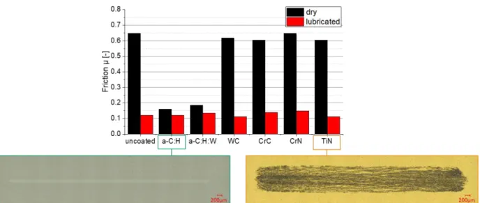
However, amorphous hydrogenated carbon coatings (a-C:H) [36] demonstrated in tribometer tests promising frictional and wear properties in a lubricant-free sliding contact with aluminum, see Figure 13. For this reason, a state-of-the-art a-C:H coating system was selected for the continuative coating development.
Figure 13: Evaluation of tool coatings in a lubricated and dry sliding contact against aluminum EN AW-1050 in ball-on-disc tribometer tests – signifi- cant reduction of friction and wear by using amorphous hydrogenated carbon coatings (a-C:H)
The referential a-C:H coating system was subject of numerous investigations of the Fraunhofer IST [37–39]
and deposited as follows. Using the BAS PM 450, sputter cleaning with an argon plasma took place before each coating process for 30 min. This was followed by the deposition of an approximately 200 nm thick tita- nium adhesion layer by sputtering a titanium-target. Subsequently, the a-C:H functional layer was deposited based on a PACVD process using acetylene (C2H2) as precursor. The layer architecture and coating properties of the referential a-C:H layer system are summarized in Table 5.
Table 5: Properties of the referential a-C:H coating system (roughness measured on polished and coated steel sampled made of bearing steel 1.3505)
Property Value
Thickness µm 2.4
Hardness HUpl GPa 32
Modulus of indentation GPa 185
Adhesion class - 1 – 2
Hydrogen content at.-% 17 Arithmetical mean height Ra nm 13 ± 1
Maximum height Rz nm 78 ± 7
5.2.2 Run-in behavior of a-C:H tool coatings
According to the current state of knowledge, a-C:H coatings are characterized by a very low friction and wear tendency compared to a variety of materials due to the surface passivation and the intrinsic property of self- lubrication [40]. Although these properties predestine a-C:H coatings as tool coatings for lubricant-free alumi- num forming, no lubricant-free deep drawing processes of aluminum alloys are currently known in the indus- try, thought also by using state of the art a-C:H coatings a rapid tool failure occurs due to adhesion formation.
An explanation can be found in the running-in behavior of a-C:H coatings, which describes a short period of higher friction and wear at the beginning of a sliding contact. Current theories explain this behavior with the necessity for transfer layer formation and a smoothing of the nanoscopic coting roughness [40], as it is typically present in the Ra range of 15 to 50 nm after coating deposition. The investigations of Heinrichs [41] and Westlund et. al [42] attribute the adhesion behavior solely to the nanoscopic layer roughness. In both studies the formation of aluminum adhesions was prevented by mechanically polishing of a-C:H coatings obtaining an average surface roughness of Ra 2 nm. On the basis of the laboratory tests, Heinrichs then postulated a high potential of polished a-C:H coatings for the realization of lubricant-free forming of aluminum. Following this thesis, the running-in behavior as a cause of failure of a-C:H coated deep-drawing tools will be investigated in more detail and the application potential of a-C:H coatings for lubricant-free deep-drawing will be verified.
For this purpose, the wear mechanisms prevailing during running-in and their effects on the tribological layer properties are analyzed in laboratory and model tests.
Ball-on-sheet tribometer tests revealed, that the nanoscopic roughness of coated steel surfaces are smoothed out while the tribological properties gets significantly improved, see Figure 14. In order to investigate the smoothing process in more detail, after testing the adhesions were removed with the aid of a sodium hydroxide solution (50 g NaOH to 1 l water) and the surface topography of the worn a-C:H coating was analyzed. While
hardly any change in the coating topography is visible at the high friction level, a significant reduction of the surface roughness takes place after reaching the medium friction level. At the beginning of the constantly low friction level, the roughness asperities are successively removed and the nanoscopic a-C:H coating topography is completely smoothed. Instead of the asperities, the micro- and nanoscopic scale now shows longitudinal grooves which are aligned along the oscillating direction of motion. The wear characteristics indicate an abra- sive removal of the a-C:H layer, which leads to an overall reduction of the layer roughness of approximately 90%. Finally, the average height of the layer roughness Sa is approx. 2 nm, corresponding to the optimum roughness value reported by Heinrichs [41].
Figure 14: Friction and roughness development of a-C:H coatings in contact with aluminum during the run-in period [43]
Continuative tribological tests in [43] showed, that the observed improvement of the tribological properties are still prevalent in contact with untested aluminum sheets. Thus, these effects can only be explained by the surficial changes of the a-C:H coating. To validate the potential for industrial dry forming processes, a-C:H coatings in run-in state were tested in strip drawing tests. Also, under these application nearer test conditions an improvement was observable and maintained for a short time, see Figure 15. However, the CoF and wear progression on the sheet metal strip indicated a rapid adhesion formation after 14 strokes - simultaneously with a change of the sheet metal strip. This progression was reasoned with an insufficient pretreatment and thus a too high nanoscopic roughness of the a-C:H coated strip drawing tool, see Figure 16.
The investigations confirmed the high potential of a-C:H tool coatings for the realization of lubricant-free cold forming of aluminum sheets by deep drawing. As can be seen from the tribometer and strip drawing tests with state-of-the-art a-C:H coated tools and a-C:H coated tools in run-in state, the tribological properties described as run-in behavior lead to rapid tool failure, comparable to an uncoated tool. The transfer layer formation described by Scharf et. al [44] was observed in the tribometer tests during the running-in period, but the transfer layer was not confirmed as a decisive influencing factor in the application tests. Instead, the nanoscopic a-C:H layer roughness was identified as the main cause for rapid adhesion formation.
Based on these test results the wear model of a dry sliding contact between a-C:H coatings and aluminum proposed by Heinrichs [41] was extended and detailed in [45]. The extended wear model specified precisely the a-C:H boundary conditions under which an adhesive tool wear can be prevented and allowed a deduction of possible methods to produce a-C:H coated forming tools for dry forming of aluminum:
- low micro- and macroscopic surface roughness to avoid mechanical clamping of aluminum
- low nanoscopic surface roughness and especially low attack angles of the roughness peaks to reduce the true contact area and aluminum oxide layer damage
- a high coating hardness to improve abrasion resistance and maintain a smooth surface roughness - intrinsic ability for self-passivation and passivation of damaged aluminum surfaces
Figure 15: CoF and wear development of a-C:H coated tools in strip drawing tests after pre-conditioning [43]
Figure 16: Second Electron Microscope image and Atomic Force Measurements of an a-C:H coated strip drawing tool after pre-conditioning – Roughness values indicate an unfinished run-in state of the a-C:H coated tool surface based on [43]
According to the simulations of Pastewka et. al [46], a higher hydrogen content improves the surface pas- sivation of a-C:H layers. However, this would reduce the hardness of the a-C:H layer, which is contrary to the goal of achieving the highest possible wear resistance. A further approach is to optimize the surface passivation by a specific modification with foreign elements. For this purpose, investigations with silicon-modified a-C:H layers (a-C:H:Si) were carried out [47]. The aim was to reduce the friction and adhesiveness by nanoscopic silicon particles, which leads to an exceptionally low CoF in sliding contacts with steel surfaces [48]. However, this tendency could not be confirmed in contact against aluminum. The tribological properties deteriorated with increasing silicon content in the a-C:H coating. An alternative is presented by Zhang et. al [49] and Sen et. al [50] who investigated a fluorine-modification of a-C:H coatings (a-C:H:F). Based on laboratory tests and simulations of the surficial interactions they reported a significant improvement of the tribological properties in contact with aluminum. These properties were reasoned with stronger C-F binding forces which leads to a higher passivation grade of the coating surface. Furthermore, Sen et. al stated the ability of a-C:H:F coatings to passivate aluminum radicals in the contact area by forming AlF3 bonds.
Like the strip drawing tests with pre-conditioned a-C:H coatings have shown, another approach can be the improvement of the running-in behavior by adding a lubricating film in the sliding contact until the optimum surface condition is achieved. Instead of using fluidic lubricants, a top layer with self-lubricating properties can be applied, which grants a graded transition into the a-C:H-layer. While the top layer gets abraded, the
a-C:H functional layer will be smoothened. Furthermore, the true contact surface to the a-C:H-surface is addi- tionally reduced by inclusions in the spaces between the a-C:H-roughness peaks. For the top layer, subse- quently referred to as the running-in layer, a variety of materials can be used [26]. Soft metals (tin, silver, lead, indium) exhibit very good friction and wear properties at high pressures and can be easily applied by PVD processes. Alternatively, industrially established dry lubricants can be considered, which have been specially optimized for use in aluminum forming applications.
Since mechanical polishing has been successfully tested in [41], further posttreatment processes for coating smoothing should be considered. Another approach is sputter cleaning and etching coated forming tools. This method is typically used to remove impurities and oxides from the substrate surface leading to an improved adhesion of the coating system to the base material. Using hydrogen or oxygen as process gas, this process can be supplemented by chemical etching [51,52]. Depending on the process gas parameters, different surface structures can be obtained. One advantage of this method is the simple integration into existing coating pro- cesses as posttreatment process.
The simplest and most effective solution is the direct deposition of a-C:H layers with a sufficiently high surface quality. However, this development approach entails a larger development process, since the entire coating architecture influences the resulting surface roughness. If the layer architecture is changed, not only the layer roughness must be improved, but also the layer properties (adhesion, hardness, etc.) which have been the focus of attention up to now must be considered.
Each of the four listed approaches was implemented on a laboratory scale and examined with regard to its suitability for lubricant-free deep drawing of aluminum. Beside a final qualification of mechanical polishing, the approaches with the highest potential for wear reduction are then tested in model experiments and evaluated in comparison.
5.2.3 Fluorine-modification of a-C:H coatings
The coating processes were carried out with the DLCarbon 550 coating plant. For the deposition of the fluo- rine-modified coating system, two fluorine-containing hydrocarbons are used as precursors - difluorobenzene (C6H4F2) and octafluoropropane (C3F8). To vary the F-content, these precursors are separately mixed in differ- ent ratios with acetylene (C2H2) and partly with Argon. Furthermore, the process pressure and the generator power are varied. Due to the lack of PVD technology in the coating plant, no metallic adhesion layer can be used. Instead, the a-C:H:F coating system contains an a-C:H:Si adhesive layer. In previous investigations at Fraunhofer IST, chemical etching of the previously deposited a-C:H:Si adhesion layer was observed during a C:H:F deposition. However, this effect did not occur in combination with an a-C:H layer. Therefore, the a- C:H:F coating system is supplemented by an additional a-C:H intermediate layer. More detailed information about the coating properties are stated in [45].
Figure 17: CoF of a-C:H:F coatings with varying hardness and F-content in a sliding contact against aluminum [45]
A detailed description of the tribological evaluation is presented in [45] using a multi-stage oscillating ball- sheet tribometer experiment. According to the test results, the a-C:H:F coatings showed nearly the same tribo- logical properties like the already tested state-of-the-art a-C:H coating systems. Like in the previous tests, running-in behavior occurs in all cases, which is characterized by material removal from the sheet and high friction. However, the fluorine-modification showed beneficial effects with regard to the CoF. Here, a tendency
to frictional decrease with increasing coating hardness and decreasing F-content can be observed, see figure 17. Consequently, a fluorine modification is not appropriate for the realization of a lubricant-free aluminum sheet forming.
5.2.4 a-C:H coating system with running-in top layer
The development of an a-C:H coating system with a running-in top layer based on the referential a-C:H coating system. Two different strategies for the deposition of running-in layers were focused. The first approach is to extend the coating process of the a-C:H coating system by a PVD deposition of a top layer made of soft metals.
After the deposition of the a-C:H functional layer, the tool surface was additionally argon etched and then deposited with tin (Sn) or silver (Ag). Both materials are known for their friction and wear reducing properties [26]. Compared to other soft metals, such as lead, indium or gold, the use of these metals leads to a better ecological and economical balance of the resulting a-C:H tool coating. The thickness of the top layer of 200 - 300 nm is determined by the maximum peak roughness height of the a-C:H coating system (see Table 5) and the thickness-dependent tribological properties, which optimum lays within the range of 100 to 500 nm. As a second approach, layers of water-miscible graphite (Lubrodal F21) and molybdenum disulphide (Kolligeen W115) are applied in an immersion process. The layers are applied as water dispersion in a mixing ratio spec- ified by the manufacturer. After the dipping process, the test specimens are cured with the coated surface vertically arranged to guarantee a homogeneous and thin layer. As can be seen from the SEM overview photos in Figure 18, the MoS2 layer shows a significantly poorer wetting behavior compared to graphite. At isolated points, the a-C:H surface emerges between the MoS2 layer. In contrast, the graphite layer is much more com- pact and is able to cover the a-C:H surface completely.
Figure 18: SEM images of a-C:H coating systems with running-in top layer based on tin and silver (cross sections in top row) and MoS2 and Graphit (overview images in lower row) [45]
Initial ball-on-sheet tribometer tests showed a high potential to prevent an adhesion formation using the PVD based Sn layer and the immersion based MoS2 and graphite layers. However, in strip drawing tests a rapid tool failure occurred. In all three cases, adhesions were formed along the line contact of the cylindrical tool and also on the outlet of the flat tool during the first 10 strokes (1 m sliding distance), see Figure 19.
Figure 19: Adhesive wear of a-C:H coated strip drawing tools with additional running-in layers after 10 strokes [45]
According to SEM analysis, the running-in layers sheared off and did not remain in the valleys of the a-C:H surface structure, see Figure 20. After a short sliding distance, the aluminum sheet was in a direct contact with the nearly unconditioned a-C:H surface leading to the typical adhesive wear. Thus, the adhesion of the running- in layer to the a-C:H surface is a decisive criterion for enabling lubricant-free forming. To prevent a delami- nation of the running-in layer, the adhesive forces between the a-C:H and the running-in layer must be greater than the cohesive forces within the running-in layer and greater than the adhesive forces between the running- in layer and the aluminum sheet. Furthermore, the hardness of the running-in layer should be increased to improve the abrasive wear resistance and to prolong the transition period.
Figure 20: SEM images of a-C:H coated test samples with various running-in layers after tribometer tests against aluminum sheets [45]
5.2.5 Nanoscopic smooth a-C:H coatings
Goal of the third and fourth development approach was the creation of nanoscopic smooth a-C:H coatings.
Plasma-assisted etching represents a post-treatment process for the targeted smoothing of the nanoscopic roughness of the referential a-C:H coating system. For this purpose, test specimens previously coated in the
BAS PM 450 are post-treated in the DLCarbon 150 PACVD coating system using a hydrogen (H2), oxygen (O2) or argon (Ar) plasma. Beside a variation of the working gas, the process performance, the working pres- sure and the gas flow are varied. In preliminary tests the argon plasma showed comparatively lower removal rates. Therefore, the treatment time is doubled to 40 minutes compared to the other gases. A more detailed description of the experimental setup is stated in [45]. According to tribological tests, argon etching represents a promising alternative to mechanical polishing of a-C:H coatings, whereas the usage of hydrogen and espe- cially oxygen leads to an increased adhesion rate. For this reason, a-C:H coated strip drawing tools are also post-treated by plasma-assisted etching with the most promising parameters: process power of 450 W, a work- ing pressure of 21 Pa and an argon flow of 125 sccm. Preliminary investigations showed that the tool material selection also affects the resulting surface roughness. The carbide precipitations of the 1.2379 cold work steel protrude from the tool surface after polishing and coating [53,54]. Thus, the powder metallurgical cold work steel Vanadis 4 Extra Clean was used which exhibits with a high surf finish. The resulting surface topography and roughness values of the plasma etched a-C:H coating is presented in Figure 21.
Figure 21: Roughness values and coating properties of the referential and developed a-C:H coating systems [53]
The direct deposition of a nanoscopic smooth a-C:H coating system was focused in a further series of tests.
During the development the complete coating system was reconsidered, since it determines the resulting sur- face roughness in its entirety. By using a metallic adhesion layer, various growth morphologies can be created depending on the deposition parameters of the magnetron sputtering process [55]. However, in order to mini- mize the development effort in this first consideration, the metallic adhesion layer was substituted by an a- C:H:Si adhesive layer analogous to the a-C:H:F coating system in Section 6.2.3. This coating class is well known to grow very homogeneously and is therefore characterized by a very smooth surface [56,57]. An indi- cation of the ideal PACVD process window is given by the detailed coating characterization of the developed a-C:H:F coatings, see [45]. Here the coating roughness decreased with decreasing process performance and decreasing working pressure. Pre-tests using acetylene confirmed this tendency also for pure a-C:H coatings.
For this reason, a parameter window at the limit of the PACVD coating plant DLCarbon 550 is set up for the development of smooth a-C:H coating systems with a targeted layer thicknesses in the range of 2 to 4 µm [53].
Analog to the plasma etching, the powder metallurgical cold work steel was used as tool material. The resulting surface topography and roughness values of the nanoscopic smooth a-C:H coating is presented in Figure 21.
For a more application nearer evaluation of the tribological properties of polished a-C:H coatings, strip drawing tools were manually polished afterwards the deposition process. The polishing was performed manually using
a 3 µm diamond paste in combination with a diamond stone and cotton cloths as polishing bodies. The polish- ing work was interrupted periodically to control the polishing success and to prevent an inhomogeneous layer removal. The resulting surface topography and roughness values of the manually polished a-C:H coating is presented in Figure 21. Polishing of the a-C:H coating lowered the nanoscopic roughness by 66%. In case of the cold work steel 1.2379, the transitions to the carbide precipitations were also smoothed leading to a micro- scopic roughness reduction by 42%.
Figure 22: CoF and images of the worn tools (1.2379) after lubricated and dry strip drawing tests with the referential and polished a-C:H coating sys- tem
Figure 23: CoF and microscope images of the worn tools (Vanadis 4 Extra Clean) after dry strip drawing tests with the referential, plasma etched and directly smooth deposited a-C:H coating system
All variants were evaluated in application-oriented strip drawing tests. The referential a-C:H coating showed a low adhesion tendency and low friction value in lubricated strip drawing tests, see Figure 22. Without lubri- cation, aluminum adhesions were immediately formed on the tool surface and the friction value drastically increased, see also Figure 23. Using the polished a-C:H coating in unlubricated strip drawing tests, only small and non-critical aluminum adhesion formed on the tool surface (Figure 22). Furthermore, the friction value decreases by 72% in comparison to the unpolished coating. These findings verified the nanoscopic a-C:H roughness as an important factor to enable aluminum dry forming processes. The plasma etched and directly smooth deposited a-C:H coatings showed an insufficient improvement of the tribological properties for ena- bling dry forming of aluminum (Figure 23). The process parameters of the plasma edging were derived from previous investigations with a differing substrate geometry. The geometry possibly influenced the plasma con- dition and thus the efficiency and effect of the etching process. In case of the a-C:H coating system with a natively smooth surface roughness the friction value and adhesion tendency were noticeably reduced. More detailed analysis of the worn tool surface indicated a very low adhesion tendency of the optimized coating system [53]. The main reason for the adhesion formation and higher friction value were microscopic asperities
caused by the precipitations of the cold work steel which protruded from the tool surface after the polishing of the tool coating and superposed the nanoscopic roughness of the a-C:H coating system.
5.3 Work piece
5.3.1 Influence of alloying elements
Within the framework of the priority program, the question frequently arose as to whether certain alloying elements of the workpiece material favor the formation of aluminum adhesions. Some references to this can be found in the literature [58–61]. In the course of the project, an attempt was made to collect and analyze evidence for this thesis beyond the phenomenological approach. Figure 24 shows an attempt to analyze the wear zone of two different aluminum alloys. EN AW-5083 has magnesium as its main alloy component, while EN AW-6082 has magnesium and silicon.
Figure 24: Worn tool surface made of 1.2379 against EN AW-5083 and 6082, photographic overview and EDS image of the cut cross section
The chromium carbide precipitations on the surface, which are typical for this tool material, are clearly visible.
These precipitations mostly protrude from the base material as hard tips and are mostly described as not ben- eficial for dry forming.
Figure 25: Mechanical properties of the aluminum alloys used in hardened or naturally hard and soft annealed condition [35]
In order to be able to make a statement on the basis of the images about the thesis made at the beginning, it would have to be possible to represent the aluminum material with such a high resolution that a resolution of the various alloying elements in the corresponding compounds and states is possible using EDS images in a scanning electron microscope or comparable analysis methods. In the images shown here, this is not possible, at least not with the analytical equipment available at the PtU, since neither magnesium nor silicon could be
detected in significant proportions. In order to be able to answer the question of an alloy dependence of the adhesive wear nevertheless, a phenomenological approach was chosen. The objective was to test as many aluminum alloys as possible, which differ from the alloy elements, for their susceptibility to wear in a strip drawing test. All alloys were supplied in the form of sheet metal plates with a thickness of 1.5 mm. It was decided to order the alloys in their hardened or naturally hard variant. To analyze the influence of the heat treatment condition on the wear behavior, all alloys were additionally soft-annealed. Soft annealing reduces typical material parameters such as tensile strength, yield strength and hardness. 25 shows the achieved me- chanical properties in the form of a bar chart. It can be seen that in the case of the naturally hard alloy 5083, hardly any influence on the mechanical properties can be exerted by an annealing process. This alloy has the lowest tensile strength and hardness in the tested field. In contrast, the alloy 2017A with a tensile strength >450 N/mm² and a Vickers hardness of 134 (HV1) is the hardest alloy in the field. These alloys were examined for their susceptibility to wear after any heat treatment in a strip drawing test in a single stroke. For this purpose, 100 mm/s was chosen as the drawing speed and 9 kN as the contact pressure. The results of the strip drawing tests are shown in 26.
Figure 26: Peak and cavity volume in correlation with hardness [35]
Shown is the cavity and peak volume of the tool surfaces. These were digitized in advance using confocal white light microscopy and then evaluated. Especially the tip volume allows a statement about the adhered volume on the tool surface. For all alloys, the soft version shows the higher wear volume in relation to the stroke length achieved. With alloy 6061, due to the very low tensile strength, only a stroke length of approxi- mately 20 mm could be achieved before the sheet tears due to the high tensile forces caused by tool wear.
Therefore, the wear volume appears to be significantly lower. Basically, with the exception of alloy 6061, it can be determined that the susceptibility to wear decreases with increasing hardness. This corresponds to com- mon wear theory [26]. According to this, the strip drawing tests with the material 2017A show the lowest adhesive tool wear. The reason for the high wear volume of alloy 6061, despite its very high similarity to material 6083 in terms of mechanical properties, is still unclear at this time, but cannot be clearly clarified with the available methods.
5.3.2 Surface topography (sheet metal)
According to chapter 6.a.i, the contact normal stress plays a decisive role in dry forming, but alone is not sufficient to enable dry forming. Considering the underlying mechanism, a high contact normal stress leads to a stronger deformation of the roughness peaks and accordingly to a stronger damage of the natural oxide layer.
An essential conclusion is that the same effect, which results from a reduction of the contact normal stress, can also be achieved by an adjustment of the sheet metal structure. The decisive factor here is the supporting part of the surface structure. If only a few pointed asperities protrude from the surface, the load of the tool contact is only absorbed by a very small area and considerable deformation and damage occurs at these contact points, which in turn leads to rapid tool failure due to adhesions. However, if the surface consists of plateau-shaped roughness peaks or is smoothed by polishing processes, the load-bearing part of the surface increases signifi- cantly. In a study by Flegler et al., this so-called load-bearing portion was adjusted by means of a microstruc- turing process [14], as shown in 26. Starting point for this investigation is the material 5083 with a mill-finish
![Figure 7: Strip drawing tests under varying normal contact stress. Tested was 5083 against 1.2379 (Rz=2, tool hardness = 60 HRC) [30]](https://thumb-eu.123doks.com/thumbv2/1library_info/5277397.1675853/9.893.170.710.295.682/figure-strip-drawing-varying-normal-contact-tested-hardness.webp)
![Figure 8: Contact normal stress at the drawing radius; circle section with r = 8 mm left; Lamé curve with a = b = 8 and n = 3 right [32]](https://thumb-eu.123doks.com/thumbv2/1library_info/5277397.1675853/10.893.91.778.106.387/figure-contact-normal-stress-drawing-radius-circle-section.webp)
![Figure 11: CAD construction with pyrometer holder (a), full display (b) and measuring zones in the cylinder tool at an exemplary wear mark [35]](https://thumb-eu.123doks.com/thumbv2/1library_info/5277397.1675853/11.893.87.749.805.1061/figure-construction-pyrometer-holder-display-measuring-cylinder-exemplary.webp)
![Figure 32: Exemplary temperature curve during a stroke (left), friction coefficients of different initial temperatures for tribological contact (right) [35]](https://thumb-eu.123doks.com/thumbv2/1library_info/5277397.1675853/12.893.80.787.451.667/figure-exemplary-temperature-friction-coefficients-different-temperatures-tribological.webp)
![Figure 14: Friction and roughness development of a-C:H coatings in contact with aluminum during the run-in period [43]](https://thumb-eu.123doks.com/thumbv2/1library_info/5277397.1675853/14.893.175.702.256.682/figure-friction-roughness-development-coatings-contact-aluminum-period.webp)
![Figure 15: CoF and wear development of a-C:H coated tools in strip drawing tests after pre-conditioning [43]](https://thumb-eu.123doks.com/thumbv2/1library_info/5277397.1675853/15.893.168.720.214.542/figure-development-coated-tools-strip-drawing-tests-conditioning.webp)
