Fig. 4: RGB-LED
Making Temperature glow
So you’ve picked a project of the category “Let’s make the world a better place”. Why does this project make the world a better place? How many people have burned their fingers on a hot stove? Or squinched up their faces, because the tea was cold? All this happens, because humans cannot see
temperature. But you can change that!
Your assignment will be to construct a thermometer which can tell you what temperature it is with the help of different colors.
Color Mix
Structure of the Circuit
For this assignment, you will need these devices:
3x 220 resistors
1x temperature sensor LM35
1x RGB-LED
4 long yellow cable, and 2 long and 2 short cable in blue and red RGB-LEDs
RGB-LEDs look just like normal LEDs (which you know from the introduction), but in fact, they contain 3 different kinds of LEDs! Namely a red, a green and a blue LED, that’s why it’s called RGB-LED. That poses the question why RGB-LEDs only have 4 legs and not 6. The reason for that is that the developers have already
connected the minus poles in the case.
The longest leg needs to be connected to the minus pole. If you turn the LED so that the longest leg is in the third position of the left, you can tell from the picture which of the legs belongs to which color.
You only need these three colors to display any other visible color. But more on that later.
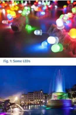
Fig. 1: Some LEDs
Fig. 2: A fountain decorated with LEDs Fig. 3: resistor,
temperature sensor and RGB-LED
Your to-do’s:
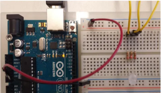
1. First, you need to connect the plus and minus ridge of the patch panel with 5V and GND on the Arduino, just like you did in the introductory project.
2. Put the RGB-LED in the patch panel, so that the minus pin is placed in the minus ridge.
All the other pins are put into an own row of the path panel. After that, each of these rows is connected to the other side of the patch panel with the help of one of the resistors. You can also put the 3 yellow cables in each of these rows, the top of them can hang loosely in the air for now.
3. After you’ve connected the Arduino with your computer, you can get started!
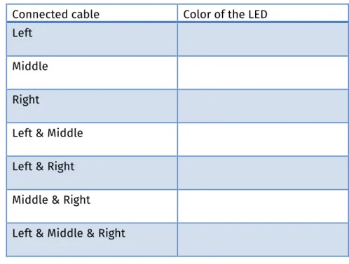
Connect each of these cables with the plus ridge and write down your observations on the next page!
Fig. 5: Complete wiring
Connected cable Color of the LED Left
Middle Right
Left & Middle Left & Right Middle & Right Left & Middle & Right
Why do these results have nothing to do with what you’ve learned in arts class?
Additive color mixture
You know the good old paint-box from arts class.
If you add the colors blue and yellow there you get green.
That works, because white light contains all the different colors. The colors from the paint-box filter some portions of the light, so that many of these portions fall away
when you mix them. If you mix all colors, all the portions are filtered and the result is black.
This is called subtractive color model. If you use RGB-LEDs you don’t take away any light but you add it together. If you mix all portions, you get white light. The basic colors are red, green and blue. With those, you can create all colors of visible light.
The same principle is used in TVs and in monitors. If you look closely at the screen, you can see that it contains many tiny red, green and blue pixels.
Of course it makes more sense to control the RGB-LED with the Arduino instead of always changing the cables. This time, don’t connect the yellow cables with the plus ridge, but instead with the digital pins 9 (blue), 10 (green) and 11 (red) at the Arduino.
Fig. 6: Color mixture
Fig. 7: Monitor screen
9,10 and 11 are special pins, which you can tell
Using your knowledge from the introductory project, we will now make the three LEDs turn on and off!
Create a new sketch for that, add the default structure and save it under a reasonable name!
Your to-do’s:
Here a quick checklist:
1. You have to add 3 variables under setting for each of the 3 LEDs. The type of the variable is .
2. The LEDs are connected to outputs ( ).
3. Switch the LEDs on and off, first one after the other and then in combination
( ).
4. Use after each switching operation, so you can see the differences . 5. Save and try it out ;-)
More than just three kinds of colors
As you know from the table on page 2, RGB-LEDs can display more than just 3 colors. To do that, you just have to switch on 2 or even 3 LEDs at the same time.
Your to-do’s:
1. Save your sketch under a new name.
Change it, so that the RGB-LED performs a play of colors in this order red, green, blue, yellow, pink, turquois and white
2. Test your program and don’t forget to save it.
All of these colors can be used later to represent different temperatures. That way, even your little sister will know the difference between hot and cold at first sight!
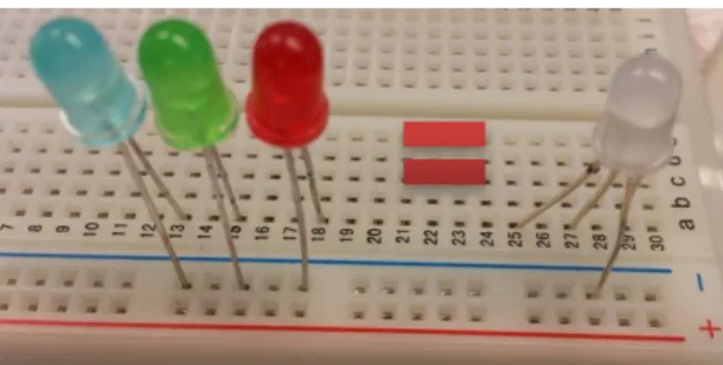
Fig. 8: LEDs in different colors and a RGB-LED
The Temperature
There are many different kinds of devices which can measure temperature. The LM35 is one of them. Even if it doesn’t look like it, it includes a complex wiring, which will simplify your work tremendously.
LM35
The LM35 has three legs. The complex wiring on the inside has to be connected to an electricity source, for that you need the outer two legs. If the flat side points towards you, then the left leg has to be connected to 5V (the plus ridge) and the right leg to GND (the minus ridge).
If the LM35 gets really hot, you connected it the wrong way
around. In that case, quickly pull the plug (don’t touch the LM35 or you’ll burn your fingers) and put it in the right way.
The middle pin does the actual temperature measurement:
For every 1° it provides 10 mV voltage. At 20° we have 200 mV.
Connect the middle pin of the LM35 with one of the analog inputs on the Arduino. Write down which one you used:
Your to-do’s:
1. To get started with the programming, create a new sketch (with the default structure) and save it under a reasonable name.
2. Copy the variables from the sketch before. Assign them the correct type in . 3. Create an additional variable for the pin of the temperature sensor. The analog
inputs of the Arduino are read out with the help of this function
This function generates values between 0 and 1023. 0 means there is no voltage, 1023 stands for the full 5 volts.
4. Before you can continue, save the sensor value in a different variable. The sensor only creates whole numbers, so you need an variable. Assign that -variable the senor
A__
Fig. 9:
LM35
Fig. 10: Wiring with LM35
So this is what we’ve got:
A sensor value between 0 and 1023
A voltage scale between 0 and 5 V
A sensor that provides 10 mV (0,01 V) for every °C
You probably guessed it: There will be a lot of converting! But don’t worry, we’ll do that step by step.
Besides the variables for the pins and the sensor value, you need two more variables.
They will save the voltage and the temperature. To calculate the temperature, you have to know how much voltage is flowing. For that, you have to convert the sensor value (which is between 0 and 1023) to voltage (which is between 0V and 5V). You can do that using this formula:
5. Since the result of a division is usually a floating point number, you need a new kind of variable: it is called float. So you add these variables under settings with these lines
6. With the help of the formula below, save the flowing voltage in the appropriate variable.
The sensor provides 0.01 volt per °C, and now that you know the voltage, you can divide that by 0.01 to know the temperature.
If you’re good at math, you know that dividing by 0.01 is the same as multiplying by 100.
That’s why you can just use the formula:
7. Add this conversion to your sketch as well.
You can’t really do anything with the calculated temperature, if it’s not displayed anywhere. You know a great tool for displays from the introduction: the serial monitor.
As a reminder, the most important commands are:
8. Start the serial monitor in and check for the sensor value, the voltage and the temperature in .
Use 5.0 instead of 5, so the Arduino calculates with floating point numbers.
You’re searching in vain for the multiplication symbol on your keyboard. Programming languages use * for multiplying.
Well, that was a lot at once. Have a look at the check list below and make sure you didn’t forget anything!
Your checklist
1. Did you save the sketch?
2. Did you add all the variables under setting and use the right types of variables?
[Note: int variables for the 3 LED pins, the analog pin and the sensor value, float for temperature & voltage]
3. Do the pin variables use the correct values?
4. Now to :
a. You don’t need a pinMode for analog inputs, but you need one for the LED pins.
b. Did you start the serial monitor?
5. In :
a. Is the value of the analog input being read?
b. Did you correctly copy the formula for temperature and voltage?
c. Are the results displayed on the serial monitor?
At last, you can tell the Arduino that it is sufficient to display the temperature every one second
using the command .
Now it is time to test your sketch! Connect the Arduino via USB with the computer and start the transfer. Look at the values on the serial monitor and complete this table:
temperature voltage sensor value
room air finger
You can use the last two rows if you have a blow-dryer or a fan.
The Color Thermometer
Is everything working? Good, now you have everything in place to measure temperature! Plus, you have a RGB-LED which can display different kinds of colors. So, you have everything to
How about letting the LED turn blue at room temperature? If it is getting warmer, maybe change it to yellow and then red? Use the following table to write down which temperature should display which color! And also which of the three LEDs has to light up for that.
temperature color R(ed) G(reen) B(lue)
Sounds like a plan! But you need to expand your sketch a little bit for that.
if-commands using conditions for advanced learners
A condition doesn’t always have to check whether two things have the same value (as a reminder: ==), but it can also check if something is less (<), greater (>) or less/greater or
equal to (<= or >=) something else.
With “ “ you can also check for more than one condition at a time. Link this condition by using “&&“. You have to add brackets around each of the conditions though. That way, the command is only carried out, if both conditions are true.
Your to-do’s:
1. Come up with an if-command for each of the temperature ranges. You only need one condition for the lowest and highest range, all other ranges need two.
2. Have the right kind of LED shine for each of the ranges. Tip: Don’t forget to switch off the other LEDs again.
If everything is working correctly, it should look like what you can see in the two pictures!
If not, have another look at your if-conditions and make sure you switched on and off the right LEDs!
On the next page, you can see how the complete wiring could look like!
Is everything working? Congratulations! If you want to continue even further, you can try the bonus assignments.
Just ask the instructors for the bonus sheet.
List of references:
Fig. 1 – Source: wikipedia.org, author: Akimbomidget (CC BY-SA 2.5) Fig. 2 – Source: wikipedia.org, author: Diliff (CC BY-SA 3.0)
Fig: 3, 9 – Source: Screenshots der Fritzing-Software (http://fritzing.org) Fig. 4, 5, 8, 10, 11, 12 – Source: InfoSphere
Fig. 6 – Source: wikipedia.org, author: Quark67 (CC SA 3.0) Fig. 7 – Source: wikipedia.org, author: Ernst Schütte (CC SA 3.0)
Light bulb - Source: pixabay.com, author: ClkerFreeVectorImages (CC0) All other graphics/icons – Source: InfoSphere
Fig. 11 and 12: Complete circuit