Exercise 7: RGA Analysis
7.1 Relative-Gain Array (RGA)
Although we introduced the structure of MIMO systems, one could still ask himself why do we have to worry about all these new concepts and why don’t we easily consider a MIMO system as a superposition of different SISO systems. In some cases, this reasoning is actually the good one, but how can one distinguish when to use this approach?
The RGA-matrix tells us how the different subplants of a MIMO plant interact: this matrix is a good indicator of how SISO a system is.
This matrix can be generally calculated as
RGA(s) = P(s).×P(s)−T (7.1)
where
P(s)−T = (P(s)T)−1 (7.2)
and A.×A represents the element-wisemultiplication (A.*A in MATLAB).
In general, each element of the matrix gives us a special information:
[RGA]ab = gain fromua toyb with all other loops open
gain from ua to yb with all other loops closed (perfect control) (7.3) Remark. It’s intuitive to notice, that if
[RGA]ab ≈1 (7.4)
the numerator and the denominator are equal, i.e. SISO control is enough to bring ua at yb. Remark. The theory behind the relative-gain array goes far beyond the aim of this course and one should be happy with the given examples. If however you are interested in this topic, you can have a look here.
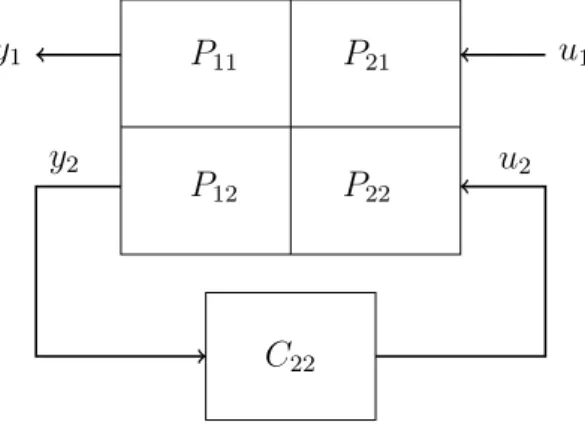
Let’s take the example of a 2×2 plant: in order to compute the first element (1,1) of the RGA(s) we consider the system in Figure 1. We close with a SISO controller C22(s) the loop fromy2 tou2 and try to compute the transfer function from u1 to y1.
Everyone has his special way to decouple a MIMO system; I’ve always used this procedure:
starting from the general equation in frequency domain Y1(s)
Y2(s)
=
P11(s) P12(s) P21(s) P22(s)
·
U1(s) U2(s)
(7.5) one can read
Y1(s) =P11(s)·U1(s) +P12(s)·U2(s)
Y2(s) =P21(s)·U1(s) +P22(s)·U2(s) (7.6) Since we want to relate u1 and y1 let’s express u2 as something we know. Using the controller C22(s) we see
U2(s) = −C22(s)·Y2(s)
=−C22(s)·P21(s)·U1(s)−C22(s)·P22(s)·U2(s)
⇒U2(s) = −C22(s)·P21(s)·U1(s) 1 +P22(s)·C22(s)
(7.7)
With the general equation one can then write Y1(s) =P11(s)·U1(s) +P12(s)·U2(s)
=P11(s)·U1(s) +P12(s)· −C22(s)·P21(s)·U1(s) 1 +P22(s)·C22(s)
= P11(s)·(1 +P22(s)·C22(s))−P12(s)·C22(s)·P21(s)
1 +P22(s)·C22(s) ·U1(s).
(7.8)
We have found the general transfer function that relatesu1 toy1. We now consider two extreme cases:
• We assume open loop conditions, i.e. all other loops open: C22≈0. One gets
Y1(s) =P11(s)·U1(s). (7.9)
• We assume high controller gains, i.e. all other loops closed: P22(s)·C22(s)1. One gets lim
C22(s)→∞
P11(s)·(1 +P22(s)·C22(s))−P12(s)·C22(s)·P21(s) 1 +P22(s)·C22(s)
= P11(s)·P22(s)−P12(s)·P21(s) P22(s) .
(7.10)
As stated before, the first element of the RGA is the division of these two. It holds [RGA]11= P11(s)
P11(s)·P22(s)−P11(s)·P21(s) P22(s)
= P11(s)·P22(s)
P11(s)·P22(s)−P12(s)·P21(s).
(7.11)
Remark. As you can see, the definition of the element of the RGA matrix does not depend on the chosen controller C22(s). This makes this method extremely powerful.
By repeating the procedure one can try to find [RGA]22. In order to do that one has to close the loop from y1 tou1: the result will be exactly the same:
[RGA]11= [RGA]22. (7.12)
Let’s go a step further. In order to compute the element [RGA]21, one has to close the loop fromy1 tou2 and find the transfer function from u1 to y2.
Remark. This could be a nice exercise to test your understanding!
With a similar procedure one gets
[RGA]21= −P12(s)·P21(s)
P22(s)·P11(s)−P21(s)·P12(s). (7.13) and as before
[RGA]21= [RGA]12. (7.14)
How can we now use this matrix, to know is SISO control would be enough? As already stated before, [RGA]ab ≈ 1 means SISO control is enough. Moreover, if the diagonal terms differ substantially from 1, the MIMO interactions (also called cross couplings) are too important and a SISO control is no more recommended.
If
RGA≈1 (7.15)
evaluated at the relevant frequencies of the system, i.e. at ωc± one decade, one can ignore the crosscouplings and can control the system with SISO tools One loop at time. If this is not the case, one has to design a MIMO controller. A bunch of observations could be useful by calculations:
• Rows and Columns add up to 1. This means one can write the matrix as [RGA]11 [RGA]12
[RGA]21 [RGA]22
=
[RGA]11 1−[RGA]11 [1−RGA]11 [RGA]11
. (7.16)
This allows to calculate just one element of the matrix.
• If one looks at RGA(s = 0) and the diagonal entries of the matrix are positive, SISO control is possible.
• The RGA of a triangular matrix P(s) is the identity matrix.
• The RGA is invariant to scaling, i.e. for every diagonal matrix Di it holds
[RGA](P(s)) = [RGA](D1·P(s)·D2). (7.17)
P11
P12
P21
P22
u1
y1
y2
C22
u2
Figure 1: Derivation of the RGA-Matrix for the 2×2 case.
Example 1. For a MIMO system with two inputs and two outputs just the first element of the RGA matrix is given. This is a function of a system parameter pand is given as
[RGA(s)]11= 1 ps2+ 2ps+ 1 (a) Find the other elements of the RGA matrix.
(b) For which values of p is the system for all frequencies ω ∈ [0,∞) controllable with two independent SISO control loops (one loop at time?
Now, you are given the following transfer function of another MIMO system:
1
s s+2 s+1
1 −s+11
(c) Find the RGA matrix of this MIMO system.
(c) Use the computed matrix to see if for frequencies in the rangeω ∈[3,10] rad/s.
Solution.
(a) Using the theory we learned, it holds
[RGA(s)]11= [RGA(s)]22= 1 ps2+ 2ps+ 1 and
[RGA(s)]12 = [RGA(s)]21
= 1−[RGA(s)]11
= 1− 1
ps2+ 2ps+ 1
= ps·(s+ 2) ps2+ 2ps+ 1.
(b) In order to use two independend SISO control loops, the diagonal elements of the RGA matrix should be ≈1 and the anti diagonal elements should be≈0. It’s easy to see that this is the case for p= 0. In fact, if one sets p= 0 one gets
RGA(s) = 1.
Hence, independently of the frequency one has, i.e. ω ∈ [0,∞), the control problem can be solved with two independent SISO controllers.
(c) Using the learned theory, it holds
[RGA(s)]11 = [RGA(s)]22
= P11(s)·P22(s)
P11(s)·P22(s)−P12(s)·P21(s)
= −s·(s+1)1
−s·(s+1)1 − s+2s+1
= 1
1 +s·(s+ 2)
= 1
s2 + 2s+ 1
= 1
(s+ 1)2. and
[RGA(s)]12= [RGA(s)]21
= 1−[RGA(s)]11
= 1− 1 (s+ 1)2
= s·(s+ 2) (s+ 1)2 .
(d) In order to evaluate the RGA matrix in this range, we have to express it with it’s frequency dependence, i.e. s=jω. For the magnitudes it holds
|[RGA(jω)]11|=|[RGA(jω)]22|
= 1
|jω+ 1|2
= 1
1 +ω2.
and
|[RGA(jω)]12|=|[RGA(jω)]21|
= 1
|jω+ 1|2 · |jω| · |jω+ 2|
= ω·√ 4 +ω2 1 +ω2 .
We can know insert the two limit values of the given range and get
|[RGA(j ·3)]11|=|[RGA(j ·3)]22|
= 1 10
= 0.10.
|[RGA(j ·3)]12|=|[RGA(j ·3)]21|
= 3·√ 13 10
≈1.08.
and
|[RGA(j·10)]11|=|[RGA(j ·10)]22|
= 1 101
= 0.01.
|[RGA(j·10)]12|=|[RGA(j ·10)]21|
= 10·√ 104 101
≈1.01.
In both cases the diagonal elements are close to 0 and the antidiagonal elements are close to 1. This means that the system is diagonal dominant and SISO control one loop at time is permitted. We just need to pay attention to what should be controlled: since the antidiagonal elements are close to 1, we need to use u1 fory2 and u2 for y1.
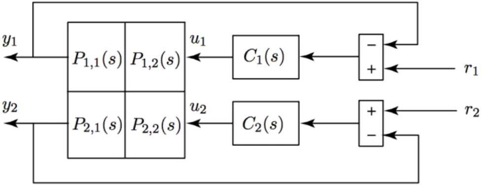
Example 2. Figure 2 shows a 2×2 MIMO system. Sadly, we don’t know anything about the transfer functions Pij(s) but
P12(s) = 0
Your boss wants you to use a one loop at the time approach as you see in the picture.
(a) Why is your boss’ suggestion correct?
(b) Just a reference ri is affecting both outputs yi, which one?
(c) Compute the transfer function ri →yj for i6=j?
Figure 2: Structure of MIMO system.
Solution.
(a) To check if the suggestion is correct let’s have a look at the RGA matrix: it holds [RGA]11 = [RGA]22
= P11(s)·P22(s)
P11(s)·P22(s)−P12(s)·P21(s)
= 1.
[RGA]12 = [RGA]21
= 1−[RGA]11
= 0.
since P12(s) = 0. This means that the RGA matrix is identical to the identity matrix, resulting in a perfect diagonal dominant system, which can be controlled with the one loop at the time approach.
(b) Let’s analyze the signals from Figure 2. Since P12(s) = 0, the output y1 is not affected from u2. Moreover, this means that the reference signal r2, which influences u2, cannot affect the outputy1. The only reference that acts on bothy1 andy2isr1: directly through C1(s) on y1 and with crosscouplings through P21(s) on y2.
(c) As usual we set to 0 the reference values we don’t analyze: here r2 = 0. Starting from the general equation in frequency domain
Y1(s) Y2(s)
=
P11(s) P12(s) P21(s) P22(s)
·
U1(s) U2(s)
=
P11(s) 0 P21(s) P22(s)
·
U1(s) U2(s)
one can read
Y1(s) =P11(s)·U1(s)
Y2(s) =P21(s)·U1(s) +P22(s)·U2(s)
Since we want to relate r1 and y2 let’s express u1 as something we know.
Using Figure 2 one gets
R1(s)·C1(s) = U1(s) +P11(s)·C1(s)·U1(s) U1 = R1(s)·C1(s)
1 +P11(s)·C1(s). Inserting this into the second equation one gets
Y2(s) = P21(s)· R1(s)·C1(s)
1 +P11(s)·C1(s) +P22(s)·U2(s).
One have to find an expression forU2(s). To do that, we look at the second loop in Figure 2 an see
R2(s)
| {z }
=0
·C2(s)−Y2(s)·C2(s) = U2(s)
U2(s) = −Y2(s)·C2(s).
Inserting this into the second equation one gets
Y2(s) =P21(s)· R1(s)·C1(s)
1 +P11(s)·C1(s) +P22(s)·U2(s)
=P21(s)· R1(s)·C1(s)
1 +P11(s)·C1(s) +P22(s)·(−Y2(s)·C2(s)) Y2(s)·(1 +P22(s)·C2(s)) =P21(s)· R1(s)·C1(s)
1 +P11(s)·C1(s) Y2(s) = P21(s)·C1(s)
(1 +P11(s)·C1(s))·(1 +P22(s)·C2(s))
| {z }
F(s)
·R1(s)
where F(s) is the transfer function we wanted.
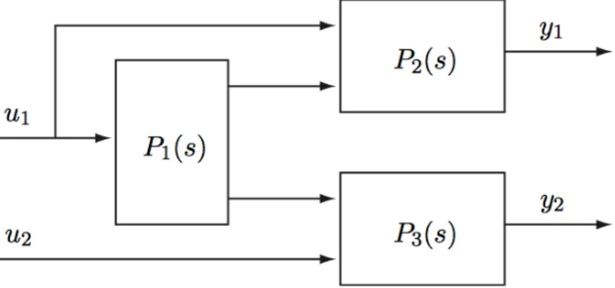
Example 3. The system in Figure 3 can be well controlled with two separate SISO controllers.
Figure 3: Structure of MIMO system.
True.
False.
Solution.
3
True.False.
Explanation:
One can observe that the input u2 affects only the output y2. This means that the transfer function matrix has a triangular form and hence, that the RGA matrix is identical to the identity matrix: this means that we can reach good control with two separate SISO controllers.