Research Collection
Doctoral Thesis
Error Identification and Error Correction for Spindle Test Setups
Author(s):
Böhl, Sebastian Publication Date:
2020-12
Permanent Link:
https://doi.org/10.3929/ethz-b-000473479
Rights / License:
In Copyright - Non-Commercial Use Permitted
This page was generated automatically upon download from the ETH Zurich Research Collection. For more information please consult the Terms of use.
Error Identification and Error Correction for Spindle Test Setups
A thesis submitted to attain the degree of DOCTOR OF SCIENCES of ETH ZURICH
(Dr. sc. ETH Zurich)
presented by
SEBASTIAN CHRISTOPH B ¨OHL
MSc ETH in Mechanical Engineering, ETH Zurich born on 24.01.1985
citizen of Germany
accepted on the recommendation of Prof. Dr.-Ing. Dr. h.c. K. Wegener, examiner
Prof. Dr. A. Archenti, co-examiner Dr. W. Knapp, co-examiner
2020
The work presented in this thesis has been carried out at the Institute of Ma- chine Tools and Manufacturing (IWF) in the Department of Mechanical and Process Engineering (D-MAVT) at the Swiss Federal Institute of Technology Zurich (ETH).
First of all, I would like to thank Prof. Dr.-Ing. Dr. h.c. Konrad Wegener, head of the IWF and supervisor of this thesis, for the opportunity which he gave to me to work in the field of machine tool metrology. I highly appreciate his trust, his constructive questions and suggestions, and his guidance through my years as PhD student. His enthusiasm for manufacturing was inspiring and motivating throughout my time at the IWF.
I am also grateful to Prof. Dr. Andreas Archenti for his agreement to take over the co-supervision and the review of this thesis. The interesting discussions on conferences and his comments in the beginning of this year were inspiring.
Special gratitude I owe to Dr. Wolfgang Knapp, my co-supervisor and former leader of the metrology group at the IWF. In particular I want to thank for his support, his personal effort, and his commitment to review and supervise this thesis. He taught me most of my knowledge in metrology with dedication and enthusiasm. This work would have not been as it is without his willing- ness for discussions, his constructive criticism, his patience in explanations, and his openness to new ideas. The work with him was enjoyable in every way.
My sincere thanks go to Dr. Sascha Weikert, my group leader, for his support and guidance in the last years. His review of the manuscript is highly appreciated. In many discussions he shared his insight in machine tool design, machine tool metrology, and modeling of machine tools. His critical and constructive questions helped to elevate this work.
I would like to thank Karl Ruhm for many discussions on the topic of error identification and correction and his willingness to share his expe- rience in metrology and system theory. Further, I would like to thank Dr. Roman Bosshard for his critical review of the electrotechnical related parts of this manuscript and Prof. Dr. habil. Andreas Kunz for his support and advice in this field of engineering.
rig components which are presented in this work. I owe special thanks to Jens Boos, former laboratory supervisor at the IWF, who introduced me to the experimental work and the measurement equipment, who provided substantial support in cases of emergency with measurement equipment and machine tools, and who enabled the fabrication of the glass ceramic frame with his expertise in machining. Thanks also go to my students Matthias Meier and Alban Imeri.
I would like to thank the company PETER HIRT GmbH and especially Daniel Hirt for his willingness for open and unprejudiced discussions, the swift responses to questions, and the support with measuring equipment.
I also would like to thank Hans Ott, Guido Florussen, and Benjamin Urbanski from IBS Precision Engineering and Don Martin from Lion Precision for their support regarding capacitive displacement measurement issues.
My special thanks go to Martina Spahni and Dr. Linus Meier, my office colleagues, who had always an open ear, gave a helping hand, and contributed substantially to a pleasant office atmosphere.
The many people with their different and enormous expertise at the IWF made life interesting, enjoyable, diversified, sometimes strenu- ous, but never boring! For that I would like to thank in particu- lar Christian Hirt, Lukas Seeholzer, Stefan S¨ußmaier, Varun Urundolil, Dr. Robert Voß, Dr. Nikolas Schaal, Christoph Baumgart, Moritz Wiessner, Pablo Hern´andez Becerro, Philip Blaser, Natanael Lanz, Dr. Fredy Kuster, Dr.-Ing. Anke G¨unther, Ewa Grob, Katalin Stutz, Miriam Fahsi, and Athina Kipouridis.
In the last years I received a lot of support and encouragement from my friends and family. Without them the last years would have not been possible in the way they were. Especially, I want to thank Fabienne for her patience, bearing with long hours, and her willingness to take a lot of load off my shoulders.
Z¨urich, August 2020 Sebastian B¨ohl
Geometric accuracy tests are an integral part of machine tool acceptance procedures. With an increasing demand for higher machine tool accuracy at lower costs and the requirement to test under shop floor conditions, the measuring task becomes more and more challenging. The field of spindle metrology is particularly affected. As permissible maximum errors decrease, a corresponding decrease in measurement uncertainty is required. A feasible strategy to cope with this is to increase the accuracy of the measurement instrumentation. However, in shop floor environments disturbances are likely to degrade the measuring performance. Not only sensors and transducers are affected, but also the mechanical setup is prone to disturbing influences. As a consequence, a gap between the measuring performance which is determined under controlled inspection room conditions and the performance under real shop floor application conditions emerges.
The objective is therefore to enable the utilization of existing and nomi- nally capable spindle measurement instrumentation in shop floor environments and on machine tools without the abatement of measurement accuracy.
The chosen approach to achieve the objective incorporates on-machine and in-process error identifications of the spindle measurement setup. The gained information are used to develop target-oriented countermeasures, improvements of the measurement setup, and correction procedures. Elec- tromagnetic interference as well as environmental temperature variations are identified as main disturbance sources. Due to the characteristics of the related error systems, cap tests are utilized for the experimental error analysis.
Electromagnetic interference markedly degrades the performance of capacitive displacement transducers which are commonly utilized for spindle measurements. However, it is shown that an electromagnetic compatible measurement setup is accomplished by the electrical insulation of the mea- suring circuit against structural components of the machine tool and thus the electrical machine tool system. A testing procedure and a corresponding testing device are proposed which enable the on-machine performance testing
In order to identify the thermal distortion of a fixture, an on-machine analysis method is proposed. The achieved measurement uncertainty is almost independent of the fixture dimensions. An experimental thermal analysis of the specific fixture indicates uniformly distributed fixture material temperatures and the admissibility of a lumped capacity assumption, which results in the expectation of thermal expansion leading to dimensional scaling without distortion. This expectation is confirmed by the experimental identification procedure. The experimental data can directly be used for the compensation of thermally induced fixture distortion.
The cap test approach is also applied for the analysis of thermally induced errors of axial displacement transducers. Clamping positions of the transducers are considered as boundary conditions in the error identification procedures. In particular, the thermal behaviors of inductive displacement transducers are analyzed. Steady state error coefficients are evaluated which allow a comparison of different transducer models and an appropriate selection of transducers. In addition, a static error correction approach directly makes use of these coefficients. For the correction of dynamic errors an observer-based correction approach is developed. In the tested cases of two inductive displacement transducer models relative error reductions in the range of 85-95 % are achieved.
Die ¨Uberpr¨ufung der geometrischen Genauigkeit ist ein integraler Bestandteil von Abnahmepr¨ufungen von Werkzeugmaschinen. Der Wunsch nach erh¨ohter Genauigkeit und die Bedingung der Abnahme unter Werkstattbedingungen stellen hohe Anforderungen an die Messprozeduren. Dies trifft auch auf die geometrische Abnahme von Werkzeugspindeln zu. Mit geringer werdenden zul¨assigen geometrischen Fehlertoleranzen der Spindeln m¨ussen in gleichem Masse geringere Messunsicherheiten der Abnahmepr¨ufung gew¨ahrleistet werden. Eine m¨ogliche Strategie zur Erreichung dieses Zieles ist es, die Messger¨atschaften zu verbessern. Zu beachten ist jedoch, dass ein Messger¨at die gew¨unschte Leistungsf¨ahigkeit unter kontrollierten Umweltbedingungen sehr wohl aufweist, die Best¨atigung ebendieser Leistungsspezifikation unter Werkstattbedingungen situationsbedingt jedoch nicht immer erreicht und umgesetzt werden kann. Dabei ist nicht nur die Sensorik umgebungsbed- ingten St¨orungen unterworfen, sondern auch der mechanische Messaufbau ist ung¨unstig beeinflusst. Infolgedessen tritt eine Diskrepanz zwischen der bestimmten Leistungsf¨ahigkeit des Messger¨ates unter Messraum- und Werkstattbedingungen auf.
Das Ziel dieser Arbeit ist es darum, die uneingeschr¨ankte Leistungsf¨ahigkeit eigentlich f¨ahiger Messger¨atschaften zur Spindelmessung auch unter Werk- stattbedingungen zu gew¨ahrleisten, so dass eine Minderung der erzielbaren Messgenauigkeit vermieden wird.
Der gew¨ahlte L¨osungsansatz zur Erreichung des Ziels ist die Identifizierung des Messger¨ateverhaltens und des Messaufbaus auf der Werkzeugmaschine, also in der Anwendungsumgebung. Die daraus gewonnen Erkenntnisse werden verwendet, um zielorientierte Gegenmassnahmen abzuleiten, den Messauf- bau zu verbessern und um Kompensations- und Korrekturprozeduren zu entwerfen. Es zeigt sich, dass elektromagnetische Interferenz und umgebungs- bedingte Temperaturschwankungen massgebliche Quellen von St¨orungen sind. Aufgrund der charakteristischen Eigenschaften der St¨oreinfl¨usse und des hervorgerufenen Ger¨ateverhaltens werden Cap Tests zur Analyse der entsprechenden Fehlersysteme verwendet.
elektromagnetische St¨orungen in Werkzeugmaschinenumgebungen beeinflusst.
Als effektive Abhilfemassnahme wird die elektrische Isolation des Messkreises von der Werkzeugmaschine respektive des elektrischen Systems der Werkzeug- maschine vorgeschlagen. Eine neu entwickelte Testprozedur mit zugeh¨origer Testvorrichtung erm¨oglicht Schnelltests von kapazitiven Sensoren auf der Werkzeugmaschine und die entsprechende Verifikation der vorgeschlagenen Massnahme der elektrischen Isolation.
Des Weiteren wird eine Analysemethode der thermisch bedingten Ver- formung einer Sensorhalterung pr¨asentiert, welche direkt auf der Werkzeug- maschine durchgef¨uhrt werden kann. Die erreichte Messunsicherheit ist unabh¨angig von den Dimensionen der Sensorhalterung. Eine experimentelle thermische Analyse der untersuchten Halterung deutet auf ein stets uniform verteiltes Temperaturfeld hin, welches eine winkeltreue thermische Verfor- mung der Halterung nach sich zieht. Ein solches Verhalten kann mithilfe der vorgeschlagenen experimentellen Prozedur nachgewiesen werden. Dies erm¨oglicht eine direkte und einfache Korrekturvorschrift der thermischen Dehnung der Sensorhalterung.
Zur Analyse des temperaturbedingten Fehlers von Axialmesstastern wird ebenfalls ein Cap Test Ansatz verwendet. Dabei wird die Konfiguration des Messaufbaus respektive die Einspannl¨ange des Messtasters als Randbedin- gung ber¨ucksichtigt. Im Speziellen wird das Verhalten von induktiven Axi- almesstastern verschiedener Baureihen untersucht. Dazu werden Koeffizien- ten evaluiert, die das station¨are Fehlerverhalten beschreiben und einen Ver- gleich verschiedener Modelle und eine zweckm¨assige Auswahl von Messtastern erm¨oglichen. Dar¨uber hinaus finden diese Koeffizienten auch Anwendung in einer statischen Korrektur des thermisch induzierten Fehlers. Um auch das transiente Fehlerverhalten zu korrigieren, wird ein modellbasierter Beobachter vorgeschlagen, der in den getesteten F¨allen eine Reduzierung thermisch in- duzierter Fehler im Bereich von 85-95 % erreicht.
1 Introduction 1
1.1 Motivation . . . 1
1.2 Erroneous Processes . . . 3
1.2.1 Error Definition . . . 3
1.2.2 Error Systems . . . 4
1.3 Geometric Machine Tool Errors . . . 5
1.3.1 Rotary Axis . . . 7
1.3.2 Linear Axis . . . 9
1.4 State of the Art in Spindle Metrology . . . 11
1.4.1 Testing Procedures . . . 11
1.4.2 Instrumentation . . . 13
1.4.2.1 Capacitive Displacement Transducers . . . 13
1.4.2.1.1 Principal Function . . . 14
1.4.2.1.2 Probe Type Transducers . . . 15
1.4.2.1.3 Cylindrical Transducers . . . 17
1.4.2.2 Optical Methods . . . 18
1.4.2.2.1 Interferometry . . . 18
1.4.2.2.2 Light Sensitive Devices . . . 18
1.4.2.2.3 Systems based on Machine Vision . . 19
1.4.2.3 Inductive Displacement Transducers . . . 20
1.4.2.3.1 Principle Function . . . 20
1.4.2.3.2 Experimental Error Analysis . . . 21
1.4.2.3.3 Application of Machine Tool Error Terminology . . . 22
1.4.2.3.4 Thermal Disturbance Behavior . . . 23
1.4.3 Erroneous Spindle Measurement Test Setup . . . 24
1.4.3.1 Thermally Induced Errors . . . 24
1.4.3.2 Analysis of Thermally Induced Errors . . . . 26
1.4.3.3 Error Separation . . . 27
1.5 Research Objectives . . . 28
1.6 Aim and Scope . . . 30
1.7 Outline . . . 31
2.2 Capacitive Spindle Measurement on Machine Tools . . . 36
2.2.1 Electrical Machine Tool Integration . . . 36
2.2.2 Interference Reduction Approach . . . 37
2.3 Interference Testing . . . 39
2.3.1 Measurement Device under Test . . . 39
2.3.2 Testing Environments and Testing Conditions . . . 40
2.3.2.1 Machine Tool Environments . . . 40
2.3.2.2 Testing Conditions . . . 41
2.3.3 Testing Device . . . 43
2.3.4 Testing Procedure . . . 46
2.3.5 Exemplary Results of Testing Procedure . . . 49
2.3.5.1 Transducer Characterization . . . 49
2.3.5.2 Disturbance Impact Analysis . . . 51
2.3.5.3 Signal Quality Assessment . . . 56
2.3.5.4 EMI Dependency on Machine Tool Type . . . 57
2.3.5.5 Discussion . . . 58
2.4 Summary . . . 59
3 Analysis of Thermally Induced Fixture Distortion 61 3.1 ISO Fixture . . . 61
3.1.1 Geometrical Errors . . . 63
3.1.2 Fixture Coordinate System . . . 64
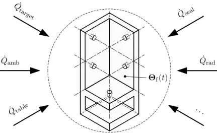
3.2 Thermal Fixture Distortion . . . 65
3.3 Principle of Fixture Distortion Test . . . 67
3.3.1 Position and Orientation Errors of Fixture-Held Dis- placement Transducer Dummy . . . 67
3.3.2 Reference Frame - Principal Function and Lateral Mo- tions on the Base Plate . . . 71
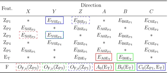
3.3.3 Evaluation Rules for a Transducer Dummy . . . 74
3.4 Implementation of Fixture Distortion Test . . . 75
3.4.1 Tested Fixture . . . 75
3.4.2 Thermal Characterization of Fixture . . . 76
3.4.2.1 Experimental Temperature Analysis of Fixture 78 3.4.2.2 Lumped Capacity Approach for Fixture . . . 79
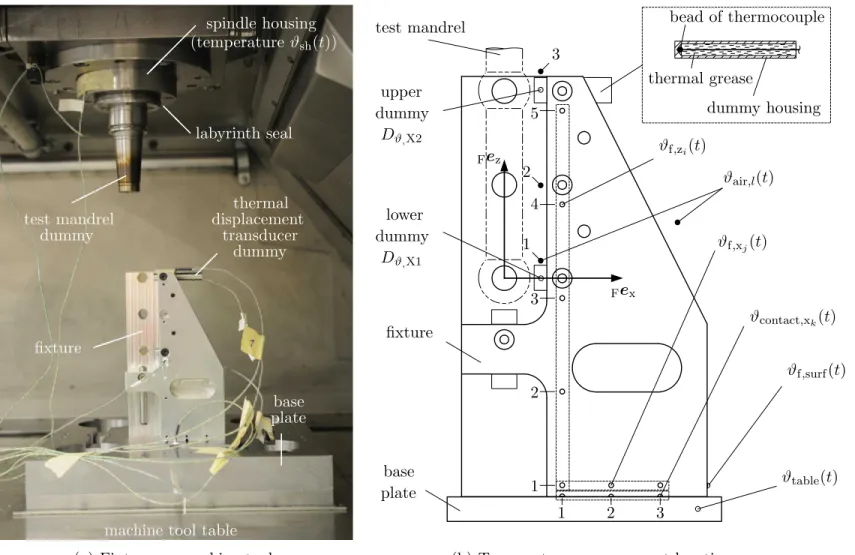
3.4.3 Mechanical Fixture Test Setup . . . 82
3.4.3.1 Reference Frame - Uncertainty due to Thermal Expansion . . . 85
3.4.3.2 Kinematic Arrangement - Setup and Uncer- tainty Budget . . . 87
3.5 Thermally Induced Error Identification . . . 91
3.5.1 Experimental Results . . . 91
3.5.1.3 Lateral Motions of the Reference Frame . . . 96
3.5.1.4 Identified Position and Orientation Error Changes of a Transducer Dummy via the Fix- ture Distortion Test . . . 101
3.5.2 Comparison of Experimental Results and Model-Based Estimations . . . 108
3.6 Summary . . . 112
4 Identification and Correction of Thermally Induced Errors for Axial Displacement Transducers 113 4.1 Modeling of a Capped Transducer . . . 113
4.1.1 Nominal Operation and Setup . . . 114
4.1.2 Cap Test for Thermal Error Model Identification . . . 115
4.1.3 Thermo-Mechanical Cap Test Model . . . 116
4.1.3.1 Thermal Model . . . 116
4.1.3.2 Thermo-Mechanical Error Model . . . 120
4.1.3.3 Evaluation of the Thermo-Mechanical Model . 123 4.2 Experimental Cap Test Setup . . . 126
4.2.1 Cap - Target and Jig . . . 126
4.2.2 Tested Inductive Displacement Transducer . . . 128
4.2.3 Displacement Evaluation Unit . . . 130
4.2.4 Generalized Measurement Process . . . 132
4.3 Thermally Induced Steady State Errors . . . 134
4.3.1 Definition of Coefficients . . . 134
4.3.2 Identification Procedure . . . 135
4.3.2.1 Experimental Boundary Conditions and Tem- perature Emulation . . . 135
4.3.2.2 Steady State Detection . . . 138
4.3.3 Experimental Identification . . . 140
4.3.4 Static Correction of Thermally Induced Errors . . . 144
4.4 Observer-Based Correction of Thermally Induced Errors . . . 146
4.4.1 Observer Model Equations . . . 146
4.4.2 Experimental Identification and Verification Procedures 148 4.4.2.1 Disturbance Input Emulation . . . 148
4.4.2.2 Signal Conditioning . . . 149
4.4.2.3 Parameter Identification . . . 151
4.4.3 Experimental Validation . . . 155
4.4.4 Comparison of Error Correction Approaches . . . 159
4.5 Summary . . . 161
5 Conclusion and Outlook 163
Appendix B Temperature Measurement 169 B.1 Generalized Measurement Process . . . 169 B.2 Temperature Sensor - Thermocouple . . . 170 B.2.1 Thermocouple Calibration . . . 171 B.2.2 Temperature Measurement Uncertainty Budgets . . . . 174
B.2.2.1 Temperature with Reference to the Tempera- ture Scale (Objective 1) . . . 174 B.2.2.2 Time-Dependent Temperature Change
(Objective 2) . . . 176 B.2.2.3 Spatial Temperature Difference (Objective 3) 177 Appendix C Thermal Parameter Estimation 179
Bibliography 183
Curriculum Vitae 201
List of Publications 202
Notation
j imaginary unit/imaginary number (j2 =−1)
q ∈R scalar
ˆ
q estimation of variable/parameter
(e.g. outcome of identification procedures)
˜
q indicator of intermediate step of signal conditioning proce- dures or uncertainty estimations
¯
q mean value
q(t) time-dependent variable (e.g. signal)
˙
q(t) = dq(t)
dt time derivative of q(t)
∂q(x, y)
∂x partial derivative of q(x, y) with respect to x
U direct voltage (DC)
U alternating voltage (AC)
Z complex impedance
p∈R1,m row vector q ∈Rn,1 column vector
q⊤∈R1,n transpose of vectorq kqk2 euclidean norm of vector q r ∈R3,1 (position) vector
ˆ
r ∈R3,1 unit vector Q∈Rn,m matrix
Latin Symbols (lowercase)
a thermal diffusivity
ae state (system) coefficient (open-loop observer) ˆ
ae identified state (system) coefficient (open-loop observer) aij element of system matrix Atm (thermo-mechanical cap test) b¯e∗y offset of linear thermally induced error characteristic
ce output error coefficient (open-loop observer)
cp specific heat capacity
cth,b thermal expansion constant of the measuring bolt ˆ
cth,b identified thermal expansion constant of the measuring bolt cui sensitivity coefficient (law of propagation of uncertainty)
d(t) displacement
dbr,i(t) displacement output signal of displacement transducer Pbr,i
d¯br,12(t) mean displacement of transducers Pbr,1 and Pbr,2
dc(t) (statically) corrected displacement signal (Chapter 3) de(t) filtered erroneous displacement signal
d‡e(t) (linear) drift corrected displacement signal d˜e(t) erroneous displacement signal
dg gap width (Chapter 1)
∆dg gap width change (Chapter 1)
din(t) displacement input signal of sensor process
ds(t) displacement transducer output signal (without noise) dTP displacement due to elastic contact deformation
(probe tip/target)
dx1(t) displacement signal output of displacement transducer PD,x1
dx2(t) displacement signal output of displacement transducer PD,x2
dy(t) displacement signal output of displacement transducer PD,y
dz1(t) displacement signal output of displacement transducer PD,z1
dz2(t) displacement signal output of displacement transducer PD,z2
ec(t) error of corrected displacement output
¯
ec mean error of corrected displacement output
ee(t) error of erroneous displacement output in comparison with nominally desired displacement output
ee disturbance input coefficient (open-loop observer) ˆ
ee identified disturbance input coefficient (open-loop observer) eij element of disturbance input matrixEtm
(thermo-mechanical cap test)
∆erel relative error change
¯
eϑ∗ offset error of steady state temperature signal
eϑ,cal,res residual temperature error after calibration (climate chamber)
e∆ϑ,0 thermally induced offset error shift of the displacement eval- uation unit
e∆ϑ,g thermally induced gain error of the displacement evaluation unit
ey(t) output error signal ˆ
ey(t) estimated output error signal e∗y(t) steady state output error signal
¯
e∗y(t) mean value of an output error signal in steady state
ey,tm(t) output error signal (thermo-mechanical cap test) ˆ
ey,xe(t) estimated thermally induced error due to a measuring bolt expansion
ˆ
ey,v(t) estimated thermally induced error due to a transducer hous- ing expansion
f frequency
fc cut-off frequency
fe throughput coefficient (open-loop observer)
fˆe identified throughput coefficient (open-loop observer) ff fundamental frequency
fh,i i-th harmonic frequency
fi element of disturbance throughput vector (thermo-mechanical cap test)
fs sampling frequency
fX, fY (empirical) frequency distribution
fˆX, ˆfY estimation of probability density function
h net height of hemisphere K and corresponding counterpart (kinematic arrangement)
hp prism height (kinematic arrangement)
hsb support block height (kinematic arrangement) k coverage factor (measurement uncertainty)
kP material constant of the probe tip (Hertzian contact) kT material constant of the target (Hertzian contact)
l length
∆l change in length
l0 initial length
l0,i,ZP5 distance between fixture clamping point H and clamping point C of the transducer dummy located in mounting bore ZP5 in directioni (i∈ {x,y,z}) (Chapter 3)
ladh adhesive gap width
lb effective measuring bolt length
lbr,ij distance between displacement transducers Pbr,i and Pbr,j
lc characteristic length (Appendix C)
lC distance between cross section CS1 and transducer dummy clamping point C in axial direction of the dummy (Chapter 3) lCS distance between cross sections CS1 and CS1
lF,i lever arm for yaw motion correction pointing in direction i lh effective transducer housing length
lh,0(ls,ref) initial transducer housing length in dependence on the refer- ence clamping length
lk distance between hemispheres (kinematic arrangement) ls clamping length of an axial displacement transducer ls,br,i clamping length of displacement transducer Pbr,i
ls,ij i-th clamping length option of thej-th jig
∆ls,j clamping length change with respect to reference conditions ls,ref reference clamping length of an axial displacement transducer ls,ref,br,i reference clamping length of displacement transducer Pbr,i
lx,OBOR distance between originsOB and OR in Bex direction ly,OBOR distance between originsOB and OR in Bey direction lzer effective structural component length (reference frame)
m mass
me¯∗y slope of the linear thermally induced error characteristic
mth thermal mass
mϑenv linear environmental temperature drift (slope of the LSLI) n rotational speed (Chapter 2 and Chapter 3) or
sample size in association with a histogram
n(t) noise signal
nb bin size in association with a histogram nd(t) displacement noise signal (sensor process) nϑ(t) temperature noise signal (sensor process) pcd partial pressure of carbon dioxide
pda partial pressure of dry air pi element of parameter vectorp ˆ
pi element of identified parameter vector ˆp pTP,max contact pressure (probe tip/target) pw partial pressure of water vapor
r radius
rK hemisphere radius (kinematic arrangement) rP probe tip or probing sphere radius
rTP radius of the circular Hertzian contact area (probe tip/target) stc sensitivity of capacitive displacement transducer (Chapter 1)
t time
∆t time difference/time shift
t0 initial time
t∗b start of the evaluation time interval Ieval tc characteristic time
t∗e end of the evaluation time interval Ieval
∆teval length of the evaluation time intervalIeval t†i trigger time
∆ts step width of the staircase temperature profile u(t) input signal (Chapter 1)
ui standard uncertainty
˜
ui uncertainty contributor (intermediate evaluation results of the law of propagation of uncertainty)
uσ¯y uncertainty of the mean signal standard deviation v(t) disturbance input signal
v∞ freestream velocity of a fluid
w width
x(t) state variable
¯
x mean value of residual errors X:= ∆res
∆xα(t) thermal expansion of the base plate in Bex direction xe(t) state variable of the open-loop observer (Chapter 4)
xe,0(t) initial state condition of the open-loop observer (Chapter 4)
∆xs(t) lateral motion of the reference frame on the base plate inBex direction
∆xs,w(t) lateral motion of the reference frame on the base plate inBex direction due to wobbling
y(t) (time continuous) signal
¯
y mean value of signal y(t)
¯
y0 reference mean value of signal y(t) y2 mean square value of signal y(t)
∆yα(t) thermal expansion of the base plate in Bey direction ˆ
yc(t) observer-based corrected displacement output signal ˆ
yc,s(t) statically corrected displacement signal ˆ
yc,s,amb(t) statically corrected displacement signal (input: ambient air temperature) ˆ
yc,s,v(t) statically corrected displacement signal (input: observer disturbance input)
ye(t) erroneous output signal, especially erroneous (referenced) dis- placement signal (Chapters 3 and 4)
ynom(t) nominal output signal yrms:=
q
y2 root mean square value
∆ys(t) lateral motion of the reference frame on the base plate inBey direction
∆ys,w(t) lateral motion of the reference frame on the base plate inBey direction due to wobbling
yϑ,e(t) erroneous (referenced) temperature signal z(t) back-loading output (Chapter 1)
z∆ϑ thermally induced shift of the reference frame inBezdirection due to thermal expansion of the kinematic arrangement
∆zw(t) wobble motion of the reference frame in Bez direction
A surface area
A∆ϑ,B∆ϑ thermally induced tilt motion of the reference frame due to thermal expansion of the kinematic arrangement
Bi Biot number
C capacity
∆C capacity change
CL transducer cable capacity
Cm measuring capacity
Cm,b equivalent measuring bridge capacity
Csgr (time-varying) shaft grounding ring capacity
C∆ϑ,0 coefficient of the thermally induced offset error shift of the displacement evaluation unit
C∆ϑ,g coefficient of the thermally induced gain error of the displace- ment evaluation unit
Ctm,iso capacity of the electrical insulator between spindle rotor and test mandrel
E Young’s modulus (Chapter 4)
Eij error motion of the j-th axis in i-th machine tool coordinate system direction (also applicable to displacement transducers) Ei0j position and orientation error of thej-th axis ini-th machine tool coordinate system direction (also applicable to geometric elements and displacement transducers)
Eϑ∗ mean steady state error bound of thermocouples
Fo Fourier number
Fp probing force
FX, FY empirical cumulative distribution function FˆX, ˆFY estimation of cumulative distribution function
G transfer function
K1(ls),K2 thermally induced steady state error coefficients
K1,br,i, K2,br,i thermally induced steady state error coefficients of displace- ment transducer Pbr,i
K1,ref thermally induced steady state error coefficient determined in reference clamping configuration
L1,L2 coil inductance of half bridge transducer LL transducer cable inductance
Nu Nusselt number
Pel electrical power (Joule heating)
Pr Prandtl number
Py signal power of signaly(t)
Py,0 signal power of signaly(t) defined as reference
Q(t)˙ heat flow
R (electrical) ohmic resistance R2 coefficient of determination
Rα,th,adh range of estimated variation for the coefficient of linear ther-
mal expansion of the adhesive
RA,w,RB,w range of tilt motions due to wobbling
Rcl range of linearity errors of the characteristic line Rdrift range of linear signal drift
Re Reynolds number
Rec range of errors of the corrected displacement output Rec,lim upper limit of errors of the corrected displacement output Ree range of errors of the erroneous displacement output
(reference: nominal displacement output)
Reϑ,cal,res range of residual temperature errors after calibration
(climate chamber) R¯eϑ∗
j,i range of mean steady state temperature errors of thermocou- ple j at temperature level i
Rγ,w range of yaw motions due to wobbling
Rhys hysteresis error range (displacement transducer)
Riso ohmic insulation resistance of the air gap between electrodes Riso,L ohmic insulation resistance of the transducer cable
RL ohmic transducer cable resistance Rres range of residual errors of a curve fit R∆res range of residual error signal
Rsgr (time-varying) ohmic resistance of the shaft grounding ring Rth thermal resistance
Rth,CH thermal contact resistance
(clamping collet/transducer housing)
Rth,TP thermal contact resistance (probe tip/target)
Rϑ(t) range of temperature variation over time (climate chamber) Rϑb(t) range of position-dependent temperatures in the base plate
(experimentally determined)
Rϑd,dev range of surface temperatures of the displacement evaluation unit
Rϑe,tc(t) range of indicated temperatures determined with a set of ther- mocouples
R¯ϑe,tc mean range of indicated temperatures determined with a set of thermocouples
Rϑenv environmental temperature range
Rϑf,xyz(t) range of fixture material temperatures
Rϑ(x,y,z) range of temperature variation in total test volume
(climate chamber)
Rtm,iso ohmic insulation resistance between spindle rotor and test mandrel
Rv ohmic loss resistance (capacitive transducer)
R∆xs,w range of lateral frame motion inBexdirection due to wobbling R¯y range of signal mean values
R∆ys,w range of lateral frame motion inBeydirection due to wobbling R∆z,w range of lateral motion inBez direction due to wobbling Syy(f) auto power spectral density of signaly(t)
Syy,0(f) auto power spectral density of signaly(t) defined as reference T temperature on the Kelvin scale
T0 initial temperature on the Kelvin scale U(t) electrical voltage (Chapter 2) or
inner energy (Chapter 4) U(k = 2) measurement uncertainty
Ucal,cc(k= 2) measurement uncertainty attributed to the calibration of the climate chamber
Ucal,d(k = 2) measurement uncertainty attributed to the calibration of an inductive displacement transducer
Ud,dev(k = 2) measurement uncertainty attributed to the displacement eval- uation unit
Ude(k = 2) measurement uncertainty of an indicated (erroneous) dis- placement
Ud,sen(k= 2) measurement uncertainty attributed to an axial displacement transducer (inductive displacement transducer)
Uδi0D5(k= 2) measurement uncertainty associated with the determined po- sition and orientation error changes of displacement trans- ducer dummy D5 (i∈ {X,Y,Z,A,C})
U¯e∗y(k= 2) measurement uncertainty of the steady state error Uγ(k = 2) measurement uncertainty of lateral yaw motion
UK1(k = 2) measurement uncertainty of the identified coefficientK1(lls) UK2(k = 2) measurement uncertainty of the identified coefficientK2
URϑe,tc(k= 2) measurement uncertainty for the temperature range estima- tion of a set of thermocouples
Uϑ¯amb(k= 2) measurement uncertainty of the mean ambient air tempera- ture
Uϑ¯b(k= 2) measurement uncertainty of the mean base plate temperature
Uϑ,dev(k = 2) measurement uncertainty attributed to the temperature eval-
uation unit
Uϑ¯e(k = 2) measurement uncertainty of an average temperature
U∆ ¯ϑe(k = 2) measurement uncertainty of changes in average temperature Uϑ¯f(k = 2) measurement uncertainty of the mean fixture material tem-
perature
Uϑnom(k= 2) measurement uncertainty of a temperature set point in the climate chamber
U∆xs(k = 2) measurement uncertainty of lateral motion of the reference frame on the base plate inBex direction
Uˆyc(k = 2) measurement uncertainty of a corrected displacement (observer-based correction)
Uˆyc,s(k = 2) measurement uncertainty of a statically corrected displace- ment
Uye(k = 2) measurement uncertainty of a referenced displacement U∆ys(k = 2) measurement uncertainty of lateral motion of the reference
frame on the base plate inBey direction
Uyϑ,e(k= 2) measurement uncertainty of a referenced temperature deter- mined with a thermocouple
Uproj projected circumference
U0 driving input voltage (alternating) Ua output voltage (alternating) Ud disturbance voltage (alternating)
Ud,p power supply origin related disturbance voltage Ud,s spindle-sided origin related disturbance voltage
Ud,t machine tool table-sided origin related disturbance voltage Um,b voltage drop at equivalent measuring bridge
Utm,iso voltage drop at insulation between test mandrel and spindle V0 total climate chamber testing volume
Vb climate chamber testing volume used for experiments Y(f) Fourier transform of signal y(t)
|Y(f)| magnitude of the Fourier transform Y(f) Zbs bearing system impedance
Zcg impedance between converter and ground (PE) Zhg impedance between spindle housing and ground (PE)
Zm measuring impedance
Zmg impedance between the driver of the measurement device and ground (PE)
Zrh impedance between rotor and motor housing Zsgr impedance of the shaft grounding ring
Ztm impedance between test mandrel and spindle rotor Zwh impedance between stator winding and motor housing Zwr impedance between rotor and motor housing
α heat transfer coefficient
αth coefficient of linear thermal expansion (CLTE)
αth,adh coefficient of linear thermal expansion of the adhesive
αth,bi coefficient of linear thermal expansion of measuring bolt com- ponents
αth,f coefficient of linear thermal expansion of the fixture
αth,f,nom nominal coefficient of linear thermal expansion of the fixture αth,h coefficient of linear thermal expansion of the transducer hous-
ing ˆ
αth,h identified coefficient of linear thermal expansion of the trans- ducer housing
αth,zer coefficient of linear thermal expansion of ZERODURR
∆ difference
∆dig resolution of the digital indication
δi0j(t) position and orientation error changes (short form ofδEi0j(t)) δi0D5(t) position and orientation error changes of displacement trans-
ducer dummy D5 (i∈ {X,Y,Z,A,C})
δi0D5,sim(t) model-based estimation of position error changes of displace- ment transducer dummy D5 (i∈ {X,Y,Z})
∆res(t) residual error (signal) ε (absolute) permittivity
ε0 vacuum permittivity
εm mechanical strain
εr relative permittivity
εRϑ upper limit of the permissible local fixture material tempera- ture variation
γ(t) lateral yaw motion of the reference frame on the base plate γw(t) lateral yaw motion of the reference frame on the base plate
due to wobbling
κ tolerance value (parameter identification procedure)
λ thermal conductivity
ν Poisson ratio (Chapter 4) or kinematic viscosity (Appendix C)
ω angular frequency
ϕ half apex angle
Ψ angular circumferential pitch of contact points (kinematic arrangement)
ρ density
σec standard deviation of errors of a corrected displacement out- put
σe∗y standard deviation of a steady state error signal
σm mechanical stress
σn standard deviation of noise signal n(t)
σrep repeatability (displacement transducer characteristic)
σRϑe,tc standard deviation of the range of indicated temperatures de- termined with a set of thermocouples
σϑ∗ standard deviation of a steady state temperature signal σϑenv,day standard deviation of the environmental temperature signal
during the daytime
σϑenv,night standard deviation of the environmental temperature signal at night
σx standard deviation of residual errors X := ∆res
σy standard deviation of signal y(t)
σy,0 standard deviation of signal y(t) defined as reference
¯
σy mean value of standard deviations σy,i
σy,cal rms resolution (equipment manufacturer calibration) σ˜ye standard deviation of an unfiltered displacement signal τc time constant of a low-pass filter
τs sampling time
τth thermal time constant ˆ
τth identified thermal time constant ϑ(t) temperature on the Celsius scale ϑ0 initial temperature on the Celsius scale
∆ϑ(t) temperature change ϑ(t)ˆ temperature estimation
ϑair,l(t) air temperature in the vicinity of the fixture ϑamb(t) ambient air temperature
ϑ¯amb(t) mean ambient air temperature (spatial average)
∆ ¯ϑamb(t) change in mean ambient air temperature (spatial average) ϑ¯∗amb mean value of a steady state ambient air temperature signal
∆ ¯ϑ∗amb difference between ambient air temperature mean values at different steady state temperature levels
ϑb(t) base plate temperature (Chapter 3) or measuring bolt temperature (Chapter 4)
∆ϑb(t) measuring bolt temperature change (Chapter 4)
ϑ¯b(t) mean base plate temperature (spatial average) (Chapter 3)
∆ ¯ϑb(t) change in mean base plate temperature (spatial average) (Chapter 3)
ϑcc(t) actual climate chamber air temperature
ϑ¯∗cc mean value of the actual climate chamber air temperature in steady state
ϑd,dev(t) surface temperature of the displacement evaluation unit ϑDϑ,i(t) temperature of the i-th thermal transducer dummy ϑe(t) erroneous (filtered) temperature signal
ϑ˜e(t) erroneous temperature signal
ϑ¯˜∗e mean value of an erroneous temperature signal in steady state ϑenv(t) environmental air temperature
ϑf(t) fixture material temperature
ϑf,i(t) fixture material temperature experimentally determined at different locations in the solid
ϑ¯f(t) mean fixture material temperature (spatial average)
∆ ¯ϑf(t) change in mean fixture temperature (spatial average) ϑf,surf(t) fixture surface temperature
ϑf,xj(t) fixture material temperature in the j-th position in Fex di- rection
ϑf,zi(t) fixture material temperature in thei-th position inFez direc- tion
ϑh(t) transducer housing temperature
∆ϑh(t) transducer housing temperature change ϑin(t) temperature input signal of sensor process ϑnom(t) climate chamber temperature set point
ϑref(t) temperature measured with reference measurement device (climate chamber calibration)
ϑs(t) temperature transducer output signal (without noise) ϑs,jig(t) cap test jig temperature
ϑsh(t) spindle housing surface temperature at the spindle nose ϑtable(t) material temperature in the machine tool table
ζ standard deviation ratio (signal quality criterion)
ζcrit standard deviation ratio threshold (signal quality criterion) ζopt optimal standard deviation ratio (signal quality criterion)
Vectors
ctm(t) output error vector (thermo-mechanical cap test) de vector of erroneous displacements (filtered)
d‡e vector of erroneous displacements (filtered, drift corrected) d˜e vector of erroneous displacements
δ vector of deviations
ey(t) output error vector (Chapter 1)
ey vector of experimentally determined displacement errors (Chapter 4)
ftm(t) disturbance throughput vector (thermo-mechanical cap test)
p parameter vector
ˆ
p vector of identified parameters ˆ
p0 initial parameter vector estimation
MrOMF(t) position vector from origin OM to point F expressed in coor- dinate system M
MrFC(t) vector from point F to point C expressed in coordinate sys- tem M
MˆrFC(t) unit vector of vectorMrFC(t)
MˆrFC,proj,xy(t) projected unit vector MˆrFC(t) onto theXY-plane
t time vector
ϑe,tc(t) thermocouple temperature signal vector
ϑf,xyz(t) vector of spatial time-dependent fixture material tempera- tures
ϑh,e vector of housing temperatures (filtered)
ϑ‡h,e vector of housing temperatures (filtered, drift corrected) ϑ˜h,e vector of housing temperatures
u(t) input vector
v(t) disturbance input vector (Chapter 1)
v vector of experimentally determined disturbance inputs (e.g. transducer housing temperature changes in Chapter 4) vtm(t) disturbance input vector (thermo-mechanical cap test) x(t) state (variable) vector
xe(t) error state vector xe,0 initial error state vector
xtm(t) state vector (thermo-mechanical cap test) ye vector of erroneous referenced displacements z(t) back-loading output vector
Matrices
Ae error system matrix (error system state equation) Atm system matrix (thermo-mechanical cap test) Be input matrix (error system state equation) Ce output error matrix (output error equation) De feedthrough matrix (output error equation)
Ee disturbance input matrix (error system state equation) Etm disturbance input matrix (thermo-mechanical cap test) Fe disturbance feedthrough matrix (output error equation) Ge back-loading output matrix (back-loading output equation)
tion)
Π matrix of conditioned experimental temperature and displace- ment data
Π˜ matrix of raw experimental temperature and displacement data
Θf(t) time-dependent fixture material temperature field Θf,0 initial fixture material temperature field
Coordinate Systems
A, B, C rotary axes about the linear axesX, Y,Z (ISO 841:2001(E)) X,Y,Z principle linear motion of a machine tool (ISO 841:2001(E)) {Mex,Mey,Mez} orthonormal basis of coordinate system M
{FeMx,FeMy,FeMz } orthonormal basis of coordinate system F expressed in coor- dinate system M
A0(GE) orientation definition of a coordinate system in A direction based on the geometrical element GE
B0(GE) orientation definition of a coordinate system in B direction based on the geometrical element GE
C0(GE) orientation definition of a coordinate system in C direction based on the geometrical element GE
OF origin of coordinate system F
OF,i(GE) i-th component of origin OF defined by the geometrical ele- ment GE (i∈ {x, y, z})
B base plate coordinate system F fixture coordinate system M machine tool coordinate system R reference frame coordinate system
Labels
A, B labels of machine tools (Chapter 2)
A, B, C, D labels of axial displacement transducers (Chapter 4) b machine tool bed (Chapter 1)
B master ball (Section 3.1)
C clamping point of the transducer dummy (Chapter 3)
C rotary axis (Chapter 1)
Cact actual rotary C-axis (Chapter 1) Cnom nominal rotary C-axis (Chapter 1)
D1, ..., D4 electromagnetic interference test cases (displacement output) Dϑ thermal displacement transducer dummy (Chapter 3)
ET fixture mounting surface
F point on transducer dummy (piercing point of the transducer dummy symmetry axis and the base plane) (Section 3.3) G switch between machine tool table and reference ground
(EMI testing device)
GCZPi geometric center or centroid of cylinder ZPi
H clamping point of the fixture
K switch between spindle-sided test setup and reference ground (EMI testing device) (Chapter 2) or
hemisphere (kinematic arrangement) (Chapter 3) M switch between spindle and test mandrel
(EMI testing device) (Chapter 2)
P process (Chapter 1) or
axial displacement transducer (Chapter 3)
Pbr axial displacement transducers measuring from the base plate against the reference frame (Chapter 3)
Pc contact point (kinematic arrangement)
PD,i axial displacement transducers measuring against transducer dummy D in direction i (Chapter 3)
PE protective earth
Pe erroneous process (Chapter 1) Pˆe,s error system (Chapter 1) Pnom nominal process (Chapter 1) Pˆnom nominal system (Chapter 1) R reference ground (Chapter 2) S1, S2 coils
Sp primary coil (Chapter 1) Ss1, Ss2 secondary coils (Chapter 1)
t tool (Chapter 1)
T switch between cap test module and reference ground (EMI testing device)
TP contact point probe tip/target
V4 electromagnetic interference test case (voltage output)
w workpiece (Chapter 1)
Z linear axis (Chapter 1)
Zact actual linear Z-axis (Chapter 1) Znom nominal linear Z-axis (Chapter 1)
ZP cylindrical mounting surface for probe P
CAL calibration conditions (measurement room/inspection room) MT OFF shop floor conditions (machine tool currentless)
NC OFF powered machine tool in base operation
NC ON powered machine tool with active position control of axis drives
SPEED powered machine tool with active position control of axis drives and spindle rotating at operational speeds
Indices
0 initial
a outlet/output
act actual
adh adhesive (gap)
air air
amb ambient
b base (Chapter 3), measuring bolt (Chapter 4), or start/beginning in combination with times
br from the base plate to the reference frame
bs bearing system
c corrected (for signals, displacements, temperatures etc.), cut-off (with frequencies), or characteristic (Appendix C)
cal calibration
cd carbon dioxide
CJC cold junction compensation cl characteristic line
cond conduction
conv convection
corr correlation
crit critical
d disturbance (Chapter 2) or displacement (Chapter 4) dev device/evaluation unit
dig digit
e error/erroneous or end (in combination with times)
env environmental
f fixture
fl fluid
g ground (respectively protective earth PE) h spindle housing (Chapter 2)
in input
iso isolation/insulation
lam laminar
lin linear
m measuring/measurement
MB measuring range
n noise
nom nominal
opt optimal situation or condition
P probe/probing
proj projected
rad radiation
res residual
rf reference frame
r rotor
s (secondary) coil (Chapter 1), shift (Chapter 3), or solid (Appendix C)
rep repeatability
seal sealing (sealing air at the spindle nose)
sen sensor/transducer
sh spindle housing (especially at the spindle nose) (Chapter 3)
sim simulation
T target (Chapter 4)
ϑ temperature
table machine tool table
target reference artifact respectively surface of the reference artifact (Chapter 3)
tm test mandrel (Chapter 2) or thermo-mechanical (Chapter 4)
turb turbulent
w stator winding of an electrical motor (Chapter 2) or wobble motion (Chapter 3)
x, y, z indication of coordinate system axis
zer ZERODURR
Superscripts
∗ steady state indicator
† trigger time indicator
‡ (linear) drift corrected
F material region of fixture solid Ieval evaluation time interval
It,cor interval used for a least squares fit (linear drift correction) N(µ, σ2) normal distribution with mean µand variance σ2
P phase respectively sequence in a climate chamber test pro- gram
R real number
R registered trade mark
TM unregistered trade mark
Abbreviations
AC alternating current
ADC analog-to-digital converter
ASME The American Society of Mechanical Engineers BIPM Bureau International des Poids et Mesures CCD charge-coupled device
CCT Consultative Committee for Thermometry CDF cumulative distribution function
CIPM International Committee for Weights and Measures CJC cold junction compensation
CLTE coefficient of linear thermal expansion CMOS complementary metal-oxide-semiconductor
D-MAVT Department of Mechanical and Process Engineering
DC direct current
EMC electromagnetic compatibility EMI electromagnetic interference ENOB effective number of bits
ETH Swiss Federal Institute of Technology Zurich EVE environmental variation error
HBT half bridge transducer
IDT inductive displacement transducer
IEC International Electrotechnical Commission ISO International Organization for Standardization ITS-90 International Temperature Scale of 1990 IWF Institute of Machine Tools and Manufacturing LSLI least squares line
LTI linear time-invariant
LVDT linear variable differential transformer LVIT linear variable inductance transducer
MPE maximum permissible error
MT machine tool
NC numerical control
PDF probability density function
PE protective earth
PSD position sensitive device/position sensitive detector PWM pulse width modulation
RMS root mean square (rms) SCR silicon controlled rectifier SGR shaft grounding ring SNR signal-to-noise ratio TCP tool center point TIR total indicator reading
TR technical report
Introduction
The underlying motivation for this work is stated first in this chapter. Af- terward, a short introduction of errors in general is given. Furthermore, the standardized error description of geometric machine tool errors is stated. Sub- sequently, the state of the art in the field of spindle metrology is described.
Based on the information given in this section, the research gap is defined and the aim and scope of this work are given. The chapter closes with an outline of the thesis.
1.1 Motivation
The prediction made by Taniguchi [181] on the development of achievable machining accuracy has been confirmed by the developments in recent years in normal, precision and ultraprecision machining. McKeown [137] empha- sizes the importance of precision engineering in future manufacturing. Shore and Morantz [172] accentuate the enabling capability of ultraprecision ma- chining for future technologies. And even on a smaller geometrical scale, Corbet et al. [52] discuss the importance of nanotechnology for manufactur- ing technologies and industry.
Nevertheless, normal machining has also become more of a challenge as it pushes forward into machining accuracy regions which had been attributed to precision machining in times when Taniguchi presented his paper. The design of precision machine tools like the PR ¨AZOPLANR [106] is driven by the de- mand for higher productivity and cost effectiveness at increased accuracy.
The characteristics of axes, drives, and measurement systems of a machine tool and the quality of their arrangement determine the achievable perfor- mance. In machining centers or milling machines the tool spindle is a crucial
component. Typically, this component is arranged in the proximity of the ma- terial removal zone and therefore directly influences the geometric workpiece accuracy and the surface finish [2,79]. Thus, the improvement of geometric ac- curacy of spindles is a research topic in science for decades. Based on research and development in industry, new developments of improved spindles enter the market continuously. This trend results in typical tolerances for radial error motion in regions from 1 nm to 100 nm for air bearing spindles or from 0.1µm to 1µm for precision ball bearing spindles.
Spindle metrology has to cope with this trend of increasing machine tool perfor- mance and seemingly vanishing geometric tolerances. This is especially true for geometric spindle acceptance testing. The absolute measurement uncertainty has to decrease to the same extent as the accuracy of the spindle increases.
The various factors influencing measuring performance, among which external disturbances play a major role, become more and more prominent for measure- ment devices of higher sensitivity. Furthermore, environmental temperature variations for instance do not only disturb the machine tool performance, but also affect the measurement by introducing errors and by increasing the mea- surement uncertainty. Therefore, spindle attributed effects and measurement errors need to be separated from each other.
Aggravating is the circumstance that acceptance tests are typically carried out with mobile measurement devices, on different machine tools, and under differing shop floor environments. This results in the endeavor of recurrent measurement setup installation, disturbance source identification, and reme- dial actions to improve the measuring performance. Especially, the two latter actions are peeving, time consuming, and costly.
The state of the art measurement devices for spindle testing are technical ma- ture and offer a nominal performance, which copes well with the corresponding demand. Nevertheless, the specified performance may not be achieved under shop floor conditions. This aspect is tackled in the here presented work, target- ing the handling of electromagnetic and thermal disturbances. The targeted deliverables are methods and procedures which enable a nearly disturbance in- variant spindle testing operation under shop floor, on-machine, and in-process conditions.
1.2 Erroneous Processes
Machine tools and measurement devices are desired to execute a specified task.
However, performances may deviate from expectations. Erroneous processes are the result. Subsequently, an error definition is given and an error model formulation is presented, which can be used to describe erroneous processes.
1.2.1 Error Definition
Ruhm [162] defines the nominal process Pnomas the process to fulfill a specified task, which means that an input u(t) results in the desired nominal output signal ynom(t). The physical implementation in the instrumental process do- main typically yields an erroneous process Pe with inputu(t) and disturbance input v(t), which may be modeled by combination of a nominal system ˆPnom
and an error system ˆPe,s. Thus, the erroneous output ye(t) is a superposition of the nominal outputynom(t) and the error signaley(t). This relation is shown in Figure 1.1. The error signal ey(t) is defined as
ey(t) := ye(t)−ynom(t). (1.1) The error thus depends on the physical process and on the expectations of the nominal behavior. In addition, the erroneous process may lead to back-loading effects. These are captured by the back-loading output z(t).
nominal process domain instrumental process domain u(t)
v(t)
nominal process Pnom
nominal system ˆPnom
nominal system ˆPnom
error system ˆPe,s erroneous process Pe
P
ynom(t) P
ey(t)
ynom(t)
ey(t)
z(t) ye(t)
−
Figure 1.1: Nominal and erroneous process according to [162].
1.2.2 Error Systems
Woschni [197] defines measurements as the estimation of input signals and describes the application of signal and system theory in metrology. The neces- sary process models, error models, and error types may be of deterministic or stochastic nature [155,156]. Hart et al. [85] give a substantial categorization of errors, considering also corrections and related uncertainties. Ruhm [160, 162]
presents a generalized linear time-invariant (LTI) error modeling approach:
The state-space description of the multiple-input, multiple-output (MIMO) error system with input vector u(t), disturbance input vector v(t), output error vectorey(t), and back-loading output vector z(t) is given by
˙
xe(t) = Aexe(t) +Beu(t) +Eev(t) with xe(t0) = xe,0, (1.2) ey(t) = Cexe(t) +Deu(t) +Fev(t), (1.3) z(t) = Gexe(t) +Heu(t) +Jev(t). (1.4) The corresponding definitions of the input and output quantities, and the matrices are indicated in Table 1.1. This error model formulation allows the distinction between internal and external errors. The former depend directly on the system input, whereas the latter are induced by disturbance inputs.
However, errors may be affected by nominal as well as disturbance inputs.
Table 1.1: Variable definition of generalized error system.
Input and output quantities
xe(t)∈Rn,1 error state vector xe,0 ∈Rn,1 initial condition vector u(t)∈Rp,1 input vector v(t)∈Rq,1 disturbance input vector ey(t)∈Rk,1 output error vector z(t)∈Rl,1 back-loading output vector
Error system state equation - Equation (1.2)
Ae ∈Rn,n error system matrix Ee ∈Rn,q disturbance input matrix Be∈Rn,p input matrix
Output error equation - Equation (1.3)
Ce∈Rk,n output error matrix Fe∈Rk,q disturbance feedthrough De∈Rk,p feedthrough matrix matrix
Back-loading output equation - Equation (1.4) Ge∈Rl,n back-loading output matrix
He∈Rl,p feedthrough matrix
Je∈Rl,q disturbance feedthrough matrix
![Figure 2.1: Schematic of interconnection between tool spindle and capacitive measurement device (electrical spindle system in accordance with [174]).](https://thumb-eu.123doks.com/thumbv2/1library_info/5295395.1677306/72.892.157.745.177.526/figure-schematic-interconnection-spindle-capacitive-measurement-electrical-accordance.webp)
![Figure 2.2: Schematic of measurement circuit under disturbance influence [31].](https://thumb-eu.123doks.com/thumbv2/1library_info/5295395.1677306/73.892.156.755.707.1039/figure-schematic-measurement-circuit-disturbance-influence.webp)
![Figure 2.6: Comparison of cap tests results in test device configurations D1 (benchmark, fully decoupled cap test) and D2 (target coupled to spindle) [31].](https://thumb-eu.123doks.com/thumbv2/1library_info/5295395.1677306/86.892.161.744.671.1019/figure-comparison-results-configurations-benchmark-decoupled-coupled-spindle.webp)
![Figure 2.7: Comparison of electrical configurations with target coupled to spindle (D2 ) and electrically decoupled spindle measurement setup (D3 ) [31].](https://thumb-eu.123doks.com/thumbv2/1library_info/5295395.1677306/88.892.163.733.170.991/figure-comparison-electrical-configurations-coupled-electrically-decoupled-measurement.webp)
![Figure 2.8: Frequency maps [31, 32]: Experiment V4 : voltage [mV], target coupled to machine tool table; Experiment D4 : displacement [µm], target coupled to machine tool table; and Experiment D3 : displacement [nm], mea-surement device insulated against](https://thumb-eu.123doks.com/thumbv2/1library_info/5295395.1677306/90.892.188.727.186.965/frequency-experiment-experiment-displacement-experiment-displacement-surement-insulated.webp)