Mechanisms and Manipulation of Ion Beam Pattern Formation
on Si(001)
I n a u g u r a l - D i s s e r t a t i o n zur
Erlangung des Doktorgrades
der Mathematisch-Naturwissenschaftlichen Fakultät der Universität zu Köln
vorgelegt von
Sven Macko
aus Duisburg
Köln 2011
Vorsitzender
der Prüfungskommission: Prof. Dr. Joachim Krug
Tag der mündlichen Prüfung: 11. Oktober 2011
Abstract
Ion beam pattern formation is a versatile and cost-efficient tool for the fabrication of well-ordered nanostructures. Furthermore, silicon is known to be a prime material in microelectronics. The thesis at hand deals with pattern formation on Si(001) through 2 keV Kr
+ion beam erosion under ultra high vacuum conditions investi- gated by in situ scanning tunneling microscopy, ex situ atomic force microscopy, scanning electron microscopy, and transmission electron microscopy. Under highly pure conditions, at room temperature, and for fluences of
F ≈1× 10²²ions m
−2, no ion beam induced patterns develop for ion incidence angles
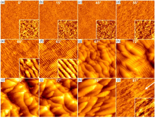
ϑ ≤55◦with respect to the global surface normal. In fact, the ion beam induces a smoothing of preformed patterns. Only for grazing incidence angles
60◦ ≤ ϑ < 81◦pronounced ripple and tiled roof patterns develop. Analysis of the fluence dependence of pattern formation was conducted at
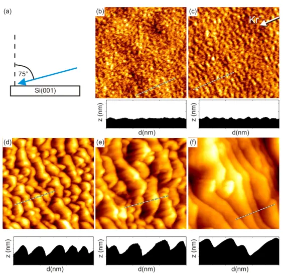
ϑ= 75◦in the unstable ion incidence angular range. The initially flat surface develops small amplitude, regular ripple patterns which then evolve to large amplitude, irregular facet patterns.
Experiments were conducted to rule out or determine the processes of relevance in ion beam pattern formation on Si(001) with impurities. Co-deposition of stain- less steel during ion beam erosion results in well developed hole, dot and ripple patterns for even small ion fluences of
F ≈ 5 × 10²¹ions m
−2. The key factor determining the type of pattern realized is the ion-to-impurity arrival ratio. While in a broad range from 140 K to 440 K pattern formation tends to be temperature independent, dramatic changes take place above a threshold temperature of about 600 K, when structures of crystalline iron silicide are shaped upon the surface. For these high temperatures nanopillars and spongelike patterns with amplitudes in the order of 100 nm and directed towards the ion beam evolve. Furthermore, variation of the angle between ion beam and impurity source has a significant effect on pat- tern formation. The larger this angle is, the more efficient the pattern formation.
This observation highlights the relevance of shadowing. Our investigations on the
phenomenology of metal assisted ion beam pattern formation identify height fluc-
tuations, local flux variations, induced chemical inhomogeneities, silicide formation
and ensuing composition-dependent sputtering to be of relevance.
Ionenstrahlinduzierte Musterbildung ist ein vielseitiges und kostengünstiges Ver- fahren für die Herstellung von regelmäßigen Nanostrukturen. Darüber hinaus ist Silizium ein maßgebendes Material in der Mikroelektronik.
Die vorliegende Dissertation behandelt die Musterbildung auf Si(001) mittels 2 keV Kr
+Beschuss unter Ultrahochvakuumbedingungen. Die Untersuchungen wur- den mittels in situ Rastertunnelmikroskopie, ex situ Rasterkraftmikroskopie, Raster- elektronenmikroskopie und Transmissionselektronenmikroskopie durchgeführt. Un- ter reinsten Bedingungen bei Raumtemperatur und Ionenfluenzen von
F ≈ 1× 10²²Ionen m−2bilden sich keine Muster für Ioneneinfallswinkel
ϑ ≤ 55◦relativ zur globalen Oberflächennormalen. Im Gegenteil, senkrecht einfallende Ionen glätten eine anfänglich raue Siliziumoberfläche. Ausschließlich für flach bis streifend einfal- lende Ionen mit
60◦ ≤ϑ <81◦bilden sich ausgeprägte Wellen- und ziegeldachartige Muster. Es wurde eine fluenzabhängige Messreihe im instabilen Ioneneinfallswin- kelbereich mit
ϑ = 75◦durchgeführt. Die anfänglich flache Oberfläche entwickelt sich über regelmäßige Wellenmuster mit kleiner Amplitude zu einem facettierten ungeordnetem Muster mit großer Amplitude.
Weitere Experimente wurden durchgeführt, um relevante Prozesse in der ionen- strahlinduzierten Musterbildung auf Si(001) unter Hinzugabe von Verunreinigun- gen aufzudecken. Bereits bei niedrigen Ionenfluenzen von
F ≈ 5 × 10²¹ions m
−2führt Kodeposition von Stahl während des Ionenbeschusses der Si Oberfläche zu ausgeprägten Loch-, Punkt- und Wellenmustern. Der entscheidende Faktor, der den resultierenden Mustertyp festlegt, ist das Ionen-zu-Verunreinigung-Flussverhältnis.
Während in einem großen Temperaturbereich von 140 K bis 440 K die Musterbil-
dung weitestgehend temperaturunabhängig ist, ergeben sich drastische Unterschie-
de oberhalb einer kritischen Temperatur von ungefähr 600 K, wobei sich kristalline
Strukturen aus Eisensilizid auf der Oberfläche bilden. Bei dieser hohen Temperatur
entwickeln sich nanoskalige Säulen und schwammartige Muster mit Höhen in der
Größenordnung von 100 nm. Die Muster sind dabei zum Ionenstrahl hin ausgerich-
tet. Änderungen des Winkels zwischen Ionenstrahl und den einfallenden Verunrei-
nigungen haben eine starken Effekt auf die Musterbildung. Je größer der einschlie-
ßende Winkel, desto effizienter ist die Musterbildung. Diese Beobachtung führt zu
dem Schluss, dass Abschattungseffekte von Bedeutung sind. Unsere Untersuchun-
gen zur Phänomenologie der ionenstrahlinduzierten Musterbildung mithilfe metalli-
scher Verunreinigungen führten zu folgenden Ergebnissen: Höhenfluktuationen, loka-
le Unterschiede im Teilchenfluss, induzierte Ungleichmäßigkeiten in der chemischen
Zusammensetzung, Silizidbildung und eine daraus folgende kompositionsabhängige
Zerstäubungsausbeute sind ausschlaggebend.
Contents
Abstract
iiiTable of Contents
v1 Preface
1Frequently used symbols
12 Fundamentals
52.1 Ion Surface Interaction . . . .
52.2 The Kinetic Monte Carlo Simulation Software TRIM.SP . . . .
112.3 Smoothing Mechanisms . . . .
132.4 Roughening Mechanisms . . . .
152.5 Gradient Dependent Surface Topography Development . . . .
192.6 Continuum Modelling . . . .
212.7 Modelling Metal Assisted Ion Beam Pattern Formation . . . .
252.8 Previous Work . . . .
263 Experimental
373.1 UHV System Athene . . . .
373.2 ex situ Measurement Methods . . . .
393.3 Sample Preparation . . . .
403.4 Data Evaluation . . . .
444 Ion Beam Pattern Formation on Si(001)
494.1 Ion Beam Induced Amorphization of Si(001) . . . .
494.2 Ion Beam Incidence Angle Dependence . . . .
504.3 Ion Beam Induced Smoothing . . . .
584.4 Fluence Dependent Pattern Evolution . . . .
594.5 Fabrication of Crystalline Ripple Patterns . . . .
665 Impurity Assisted Ion Beam Patterning on Si(001)
695.1 Impurity Induced Pattern Morphologies by Co-sputter Deposition . .
695.2 Temperature Dependence . . . .
805.3 Morphological Phase Transition: From a Smooth to a Rippled Surface . . . .
865.4 Impurity Assisted Ion Beam Patterning in the Crystalline Phase . . . .
935.5 Impurity to Ion Flux Ratio Dependence . . . .
1055.6 Fluence Dependent Pattern Evolution . . . .
1095.7 Dependence on the Directionality of Incoming Kr
+and Fe . . . .
1165.8 Co-deposition Directionality and Ion Beam Patterning: A Stability Analysis . . . .
1205.9 Directionality and Flux Ratio Dependence: A Pattern Phase Diagram . . . .
1246 Summary
1317 Outlook
135References
137A Publications
157B Ripple Profile Erosion Velocity Simulation: Gnuplot Code
159C Acknowledgements
161D Curriculum Vitae
1651 Preface
Ion beam surface patterning of amorphous and crystalline materials has attracted considerable interest in the past years. This interest is of twofold origin. First, it results from the complex physics involved in ion beam patterning which has not yet been entirely uncovered. Second, ion beam nanopatterning is a relatively cheap and low tech method for creating various regular nanoscale surface patterns over large, wafersize areas. Such structured surfaces may be used as templates for subsequent nanostructure fabrication. There are a number of potential applications: ‘Moth eye’
surfaces and facet structures with a high aspect ratio may serve as an anti-reflection surface finish due to their gradation of the refractive index [1–3]. Specifically pat- terned Si surfaces are capable of increasing the efficiency of solar cells [4–6]. Well aligned ripple patterns are a beneficial substrate for orientation of large molecules [7]. Nanoporous silicon was identified not only as a bio-compatible material sup- porting cell and apatite growth (the latter being a major component of bone tissue) [8;
9] but also being a promising material for small sensitive sensors [10]. Arrays ofpillars oriented upstanding to the Si substrate were found to be an ideal material for enhancing the performance of thermoelectric generators [11], optoelectronic devices [12;
13] as well as being useful for flat panel displays as field emitter arrays [14; 15].Finally, magnetic plain rods and pillars show interesting properties in the field of nanomagnetism [16–20]. As specified above, the variety of possible applications is manyfold.
As Si is a prime material of technology and readily available in high purity and quality, it is not surprising that the ion beam patterning studies are numerous for this material. At room temperature Si readily amorphizes during ion exposure [21].
The loss of anisotropy and crystal structure appears to make it an ideal material to
be described by the continuum theory of ion erosion, which effectively averages out
complex atomistic details of the processes.
Nanopatterns are observed by many groups following ion-beam erosion of silicon surfaces and the arrangement of individual features can be highly regular. While there are certain conditions under which ion beam erosion of Si does not cause pattern formation [22;
23], the overwhelming number of investigations find patternformation on Si in a large parameter space.
The variety and complexity of observed patterns stimulated the development of continuum theories [24–28] extending the concept of the curvature dependent yield as a prime destabilization mechanism.
However, in the past, even for similar ion-beam parameters and formation condi- tions, the type of pattern created appeared to depend on the laboratory of fabrica- tion and the ion-beam apparatus used. In this situation the question arose, whether there is a hidden chemical or impurity factor in pattern formation on Si. Such a largely disregarded attribute could make it impossible for theory to come up with an adequate description of pattern formation.
The present thesis contributes to the cognitive process of the last years that im- purities play a crucial role in the ion beam pattern formation process. Subsequently it was found that no patterns develop on Si surfaces in a large angular range of ion incidence
0◦ ≤ϑ ≤ 50◦with respect to the surface normal, if no impurities are present or co-deposited [22;
29–31]. All patterns observed in this angular range – inthe past often erroneously interpreted in terms of pure ion beam erosion mechanisms – revealed to be just a consequence of unintentional co-deposition of a non-volatile species during erosion resulting in a two-component surface system.
These findings not only prepare the ground for careful and clean ion beam erosion experiments, which may serve as an empirical basis for a theoretical description of single component ion beam erosion, they also provide a strong parameter for tuning patterns and developing new ones [32–36], qualitatively different from the patterns observed in a one component situation.
The first part of this work will address pure ion beam erosion experiments on
Si without impurities. Analyzing the resulting surface morphology of angle and fluence dependent measurements gives insight to the fundamental ion beam pattern formation mechanism.
In the second part we investigate the phenomenology of impurity driven pattern
formation on Si(001) using co-deposition of stainless steel. The goal of our analysis
lies in separating and distinguishing the most relevant factors for ion beam induced
pattern formation with co-deposition. Knowledge of such factors is a prerequisite
for an adequate modelling of this situation and thus for manipulating the resulting
patterns. Key findings relate to the effect of chemical reactions on pattern formation,
to critical fluctuations causing a pattern bifurcation as well as to local flux variations
of the co-deposited species causing its inhomogeneous lateral distribution.
2 Fundamentals
2.1 Ion Surface Interaction
This chapter deals with the phenomenology of ion surface interaction by low energy (100 eV – 10 keV) noble gas ions with silicon as a target material. The elucidated fundamentals of the present section are based primarily upon the book M. Nastasi, J. W. Mayer, and J. K. Hirvonen: Ion-Solid interactions: Fundamentals and Ap- plications [37] and the volume series R. Behrisch, K. Wittmaack, and W. Eckstein:
Sputtering by Particle Bombardment [38–40].
Collision Cascade
An impinging charged particle induces a collision cascade in a solid and causes damage in the near surface layers by transferring energy to the target atoms.
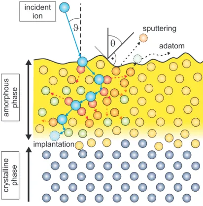
Figure
2.1illustrates the ion induced collision cascade. The impinging energetic ion (blue) with a global incident angle of
ϑinteracts within a primary collision (red) with stationary surface and bulk atoms
1. Due to the ion impact the knocked-on atoms leave their site and may still have enough energy to induce further collision events with neighboring atoms leading to secondary collisions (orange). Aside of vacancy production events and replacement collisions most of the atoms remain as interstitial atoms (green) until their kinetic energy is depleted and the energy drops below the displacement energy of a target atom. The result is a highly disordered region around the path of the ion. Near surface atoms may be sputtered that means they are removed from the surface. Not the direct collision caused by the ion but
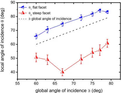
1Note that we distinguish here and in the following between theglobal angle of incidence ϑ (measured with respect to the normal of the average surface plane) and thelocal angle of incidence θ(measured with respect to the surface normal of a specific surface element).
crystalline phaseamorphous phase
incident ion
q
J
sputteringadatom
implantation
Figure 2.1: Schematic view of the ion induced collision cascade. An impinging ion (blue) induces a collision cascade. Events such as ion implantation, replace- ment collisions, vacancy production, interstitial and adatom generation, and sputtering occur. An amorphous layer forms near the surface on top of the crystalline layer (modified from [41]).
secondary collisions by atoms lead to sputtering of a surface atom. These sput- tered atoms originate from the first two layers, nearly independent of the ion energy and the angle of incidence [42]. A gauge for the erosion is the sputtering yield
Ywhich gives the mean number of sputtered atoms per incident ion. If the energy of a hit surface atom is not high enough to overcome the surface binding energy and leave the surface boundary it may act as a mobile adatom. The mobile adatom contributes to surface diffusion, before being incorporated back into the solid bulk.
By undergoing a series of collisions with the atoms and electrons in the target the ion loses energy at a rate of the stopping power
dE/dx:
dE
dx = dE dx n
+ dE dx e
(2.1)
2.1 Ion Surface Interaction
The subscripts
nand
edenote nuclear and electronic collisions, respectively.
Nuclear collisions may account for large discrete energy losses and a significant angular deflection of the ion trajectory. The energy is transmitted as translatory motion to a target atom. This process is responsible for the production of lattice disorder by displacement of atoms from their lattice positions.
The stopping power depends on the energy and mass of the ion as well as on the substrate material. The nuclear energy loss can be calculated as follows ([37] p. 94):
dE dx n
= 0.28
[eV nm
2]
Z1Z2 ΩZ1 2
1Z
1 2
2
M1
M1+M2
(2.2)
with
Ωbeing the atomic volume.
Equation
2.2is a reasonable approximation for most of the keV energy region.
For 2 keV Kr
+ions impinging upon a silicon target, as in our experiments, the nuclear energy loss calculated by equation
2.2is 235 eV/nm.
Electronic collisions between the ion and the electrons in the solid (excitation or ionization) involve much smaller energy losses per collision. Electronic stopping originates from the transfer of momentum that occurs when target electrons are cap- tured by the projectile. Those electrons have to be accelerated up to the ion velocity and the ion loses a small amount of momentum inducing a negligible deflection of the ion trajectory, and negligible lattice disorder [37].
Nuclear stopping predominates for low energies and high atomic numbers
Z1, whereas electronic stopping takes over for high energies and low atomic numbers
Z1. In our investigated energy range of keV ion bombardment the electronic excitation can be neglected. The energy transferred to electrons is small compared with the exchange of kinetic energy between the atoms [37]. The whole energy loss process slows the ion down and after it comes to rest it remains implanted (blue dashed).
The depth distribution of implanted ions in amorphous materials is expected to have a Gaussian shape and is characterized by a projected range
Rpand a straggling
∆Rp
[37].
Binary Collisions
The collision cascade may be described via binary collision approximation. As di- agrammed in figure
2.2an ion with energy
E0, velocity
v0and mass
M1hits an atom at rest with mass
M2. After collision the ion is scattered by the angle
ψand its energy and velocity is reduced to
E1and
v1while the energy
E2is transferred to the knocked-on atom recoiled by the angle
ϕ. In the investigated low energy bombardment range the mean free path between collisions is far greater than the in- teratomic spacing. The probability of three or more particle collisions is very small.
The energy transfer of a collision event is characterized by the consideration of the principles of conservation of momentum and energy. These considerations lead to following equations [37]:
Figure 2.2: Sketch of an elastic binary collision. A moving particle
M1hits a particle at rest
M2(see text).
Energy of the scattered projectile:
E1 =E0
M1
M2 cosψ±q
1−(MM1
2)2sin2ψ2
1 + MM1
2
2 , ψ ≤sin−1 M2
M1
(2.3)
Maximum energy transferable in a head-on collision:
E2max = 4M1M2
M1+M2E0
(2.4)
2.1 Ion Surface Interaction
Energy transferred to the target atom:
E2 =E2maxsin2
π−2ϕ 2
(2.5)
Angle of the scattered projectile:
tanψ = M2sin(π−2ϕ)
M1+M2cos(π−2ϕ)
(2.6) The interaction of charged particles is described in the simplest form by a Coulomb potential ([37] p. 70).Specifically in the keV energy range of particle col- lisions a screened Coulomb potential is more appropriate as the electron clouds effectively screen the nucleus [43–46].
Ion Induced Amorphization
The major energy fraction of a keV ion collision with the target is transferred to the primary recoiled atoms which in turn convert the kinetic energy to a large extent into phonon excitations of target atoms [43;
47]. The resulting local annealing amountsto a temperature of a few 1000 K and is termed thermal spike. The heat dissipates within a timescale of ps [48;
49]. In comparison the impact rate of incoming ions ona certain surface point with typically used ion fluxes is in the range of seconds i.e.
higher on the timescale by a factor of 10
9[41;
47]. Regarding room temperature ionbeam erosion experiments on silicon, the material does not recrystallize due to the
rapid quenching. This process generates defects in the near surface region. With
each impinging ion and an increasing number of collision cascades an amorphous
layer forms near the surface above the crystalline layer [50;
51]. The thickness of theamorphous layer corresponds to the mean penetration depth of the ion [41] which
depends on the energy
E0and mass
M1of the incoming ion and the mean free path
of collisions.
Angle Dependence
Shifting the angle of incidence from normal to oblique incidence the ion path is moved closer to the surface. With increasing energy deposited by the ion in the near surface region more surface atoms are affected by the collision cascade and the sputtering yield rises. Ion beam incidence angle dependent kinetic Monte Carlo (KMC) simulations for low energy noble gas ion erosion on Si and other various targets show that the maximum sputtering yield is found for oblique global incident angles with
ϑ ≥ 60◦([40] p. 101 ff.). At grazing incidence the fraction of reflected ions increases accompanied by a decrease of erosion and hence a diminished sput- tering yield. The relative width of the distribution depends primarily on the ratio between ion mass
M1and the mass of the substrate atom
M2.
Spatial Sputtering Yield Distribution
The angular sputtering yield distribution of emitted particles depends predominantly on the ion energy, the ion to atom mass ratio and the angle of incidence. For normal incident ions the angular distribution of sputtered particles may be described in a first approximation by a cosine distribution ([40] p. 4). By sputtering with heavy ions at low bombarding energies close to the sputtering threshold the majority of atoms leave the surface at large angles. Contrariwise the emission distribution is moved towards the normal direction by sputtering with light ions and higher energies ([40] p. 4, [52]). In the case of oblique ion incidence the major fraction of atoms is shifted away from the incoming ion beam. Less than 5% of the sputtered atoms are ionized; emitted atoms are primarily neutral atoms in the ground state ([38] p. 5).
Sputtering Compound Targets
Sputtering a multicomponent target leads to different partial sputtering yields for
different elements. This is due to the varying momentum transfers of the incoming
ion to the different alloy components [40]. This so-called preferential sputtering and
2.2 The Kinetic Monte Carlo Simulation Software TRIM.SP
the angular and energy distribution of the sputtered species depend on the masses and the surface binding energies of the respective species in the compound material.
At low fluence the ion induced collision cascade will change the stoichiometry in the projectile penetration range ([38] p. 3). With increasing fluence one component is removed at a higher rate so that the surface layer is enriched in the other component until a steady state condition is established ([40] p. 129). A higher ion mass leads to a lower steady state fluence. Furthermore, the different constituents may be sputtered with slightly different angular distributions.
Whereas temperature does not influence the collision cascade of one component amorphous targets (except for temperatures near the melting point), in the case of multicomponent targets diffusion and segregation can change and with it the collisional cascade ([40] p. 132, [53;
54]).2.2 The Kinetic Monte Carlo Simulation Software TRIM.SP
The Monte Carlo program TRIM (transport of ions in matter) is capable of re- producing experimental data of collisional sputtering processes [55;
56]. TRIM.SP(sputtering) is an extension of the original program TRIM and is also based on the binary collision approximation. Total sputtering yields and also more detailed information on angular and energy distributions of sputtered particles may be cal- culated [57].
As discussed in section
2.1the sputtering yield depends mainly on the projectile- target atom combination, on the energy and angle of incidence of the projectile and the surface binding energy.
For the calculation proper values for surface and bulk binding energies are nec-
essary. The program includes electronic energy loss and uses an analytic formula
which is based on realistic interatomic potentials for determining particle scattering
angles and the energy transfer to target atoms [55]. In the simulation each particle
starts with a given energy, position, and direction. Both incident particle trajecto- ries and those of the target atoms are followed collision after collision throughout their slowing-down process. The particles change their direction as a result of binary nuclear (elastic) collisions and move in a straight path between collisions until their energy is reduced by nuclear and electronic (inelastic) energy losses. The record of a moving particle ends when its energy falls below a predetermined energy or the particle leaves the target surface.
In the simulation the target atoms are localized at random locations so that the directional properties of a crystal lattice are ignored. The path length between collisions is determined from the target density [55]. This approach is feasible for amorphous target materials as in our case silicon already becomes amorphous at very low erosion fluences.
TRIM.SP uses a planar surface potential; the emitted particles have to overcome the surface binding energy which is closely approximated by the heat of sublimation given by the sum of the heat of fusion (melting) and the heat of evaporation. The surface potential causes an energy loss and a refraction for target atoms leaving the surface [57].
One needs to be careful using the simulated data for the evaluation of experiments resulting in a rough surface e.g. a patterned surface [57]. In particular considering a perturbed surface the bonding of an in-surface atom depends on the local varying coordination number. Various authors argue that the energy required to remove an atom from a rough surface should be greater by some 30% - 40% ([40] p. 236).
Simulations of sputtering multicomponent targets are only truthful in case of a non-changing target composition with erosion time. Until equilibrium is estab- lished, reflection and sputtering depend on the fluence of projectiles [42]. Therefore the static version TRIM.SP may only be used for the low fluence case or for equi- librium. For the specific case of fluence dependent preferential sputtering of multi- component materials TRIM.SP was extended under the designation TRIDYN [58].
Being suitable for dynamical calculations, TRIDYN covers simultaneously recoil
2.3 Smoothing Mechanisms
implantation, cascade mixing and surface recession [52].
2.3 Smoothing Mechanisms
Surface Diffusion
Mullins derived an equation for the height evolution considering surface diffusion.
A small slope approximation for the surface is taken into account and the atomistic nature of the crystal and crystalline imperfections are ignored [59]. Gradients of chemical potential along the surface are associated with gradients of curvature. The chemical potential changes when an atom is transferred from a point of zero curva- ture to a point of curvature
Kon the surface. Therefore such gradients produce a drift of surface atoms [60].
∂z
∂t =−DsγΩ2ns
kBT ∇4z
(2.7)
z, Ds, γ,Ω, ns, kB
and
Tdenote the surface height, surface diffusion constant, surface free energy, atomic volume, surface density of atoms, Boltzmann constant, and temperature, respectively.
Ion-Irradiation-Enhanced Viscous Flow
Ion irradiation leads to a flow within a thin amorphous surface layer with thickness
azof the ion penetration range. This thin viscous layer enhances material transport on the eroded target [61;
62]. The viscous flow is described by ahydrodynamic model treating the targets crystalline to amorphous transition as solid-liquid interface.
Besides, the model is valid in the range where the surface layer thickness
azis much smaller than the corrugation wavelength
Λ.
The viscous term is found by solving the Navier-Stokes equation in the limit
of small Reynolds numbers with no slip condition at the solid-liquid interface and
vanishing shear stress at the surface [60]. The linear approximation yields:
∂z
∂t = γa3z
3ηion ∇4z,
(2.8)
in which
ηdenotes the viscosity. In this model changes in corrugation wavelength
Λwith temperature
Tmay be attributed to a temperature dependence of the ion- induced viscosity
ηion[63].
Ballistic Smoothing
Ion impacts form subnanometer craters next to the impact point. The ballistic smoothing characterizes an ion impact-induced downhill current at the atomic scale.
In the top layer these currents cause a strong smoothing of initially rough substrates by erosion of hills into neighboring hollows.
Assuming that, the incoming ions with a local angle of incidence
θare directed towards the
−x-direction, the lateral atomic shifts in the direction of the incoming particle are
∆xi. The sum of atomic shifts enters by means of
−δcos(θ)and the flux
Φionof incoming ions enters using
Φion/cos(θ)[60].
∂z
∂t =−ΦionΩδ(E0, θ)
tan(θ) ∇2z, δ=X
i
∆xi
(2.9)
A linear relation is found between the displacement magnitude
δof the currents and the surface slope [64]. The energy dependent saturation of the impact induced smoothing is likely caused by the increase of implantation depth for higher energies.
In this case a major part of the impact energy is released in the bulk and is no more available for surface currents.
Vauth and Mayr [60] have shown by molecular dynamic simulations that surface
diffusion is a non-relevant surface smoothing mechanism for semiconductor glasses
at room temperature. Depending on the wavelength of periodic surface structures,
either surface viscous flow or ballistic smoothing dominates for smaller or larger
structures, respectively [60].
2.4 Roughening Mechanisms
Redeposition
The mechanism of redeposition describes the influence of sputtered particles which do not leave the surface entirely but are redeposited at a different distant location.
This mechanism becomes increasingly important in the case of a highly corrugated surface with high aspect ratio [25]. Particles on ridges are primarily moving away from the target whereas those from the valleys frequently reattach to the neighbor- ing sidewalls [65]. The net current of material from higher to lower lying regions is explained by the forward peaking of the sputtered particle distribution in the direction of flight of the impinging ion [25]. Hence, redeposition leads to a higher deposition rate in the depressions compared to the hillocks and associated with this the erosion velocity decreases from the top of the mountains to the lowest points of the valleys [65]. Bradley [66] showed recently that redeposition which was considered to be a prime mechanism for dot pattern formation is a nonlinear local effect and thus not the physical mechanism responsible for the formation of hexagonal arrays of nanodots.
2.4 Roughening Mechanisms
Statistical Roughening
Every single impinging ion forms an impact crater on the target surface and leads to a roughening on the atomic scale. The crater shape depends primarily on the ion energy, ion mass and angle of incidence; in our case of an amorphous Si target, due to high ion fluences the influence of crystallographic directions is not applicable.
An ion impact redistributes the target surface atoms. Low energy Ar
+ion impact craters on Si surfaces were already investigated experimentally by STM [67] and as well analyzed by molecular dynamic simulations [68].
On the basis of Benninghoven’s observation of the successive ion beam etching
of surface layers, Carter outlines a stochastic roughening mechanism [69;
70]. Therandom statistical arrival in time and space of individual ions onto the surface leads to distinct sputtering events. The outermost surface layer is eroded and simultane- ously exposes atoms in the layer below to ions arriving afterwards. With increasing fluence deeper layers are exposed to the incident ions and are sputtered gradually which leads to etch pit structures [71]. The erosion process which consists of in- dependent discrete random occurrences can be described by a Poisson distribution.
The sputtered depth conforms with the mean depth
hziof erosion and represents the expected value of the poisson distribution [70]:
hzi= Φt Y(ϑ)
n
(2.10)
The standard deviation of
hziidentifies the roughness
σand is equal to:
σ =
rΦt Y(ϑ)
n
(2.11)
While the sputtered depth increases linearly with fluence the roughness
σin- creases with the square root of the fluence.
Curvature Dependent Roughening
Sigmund introduced a roughening mechanism that depends on the surface curvature.
By analyzing the shape of the ion induced collision cascade, the author approximates the deposited energy profile inside the solid by a Gaussian [72]. The absolute value of deposited energy at the surface depends on the surface curvature. The elliptical contours in figure
2.3illustrate the deposition of the impinging ion energy inside the bulk. The erosion velocity normal to the surface at a point (
x, y) at the surface is proportional to the total energy deposited there from ion impacts at nearby points.
The total energy deposited at a surface point at a crest is lower in comparison to
the energy deposited at a surface point in a valley. This relation is indicated in
figure
2.3by differing distances from the considered ion impact points to the nearby
2.4 Roughening Mechanisms
Figure 2.3: Schematic view of the near surface energy deposition by energetic ions (see text).
centers of energy deposition. Therefore, sputtering in valleys is enhanced relative to crests which leads to a surface roughening [72].
Scattering
When a surface is rough resulting in features with a high slope, incoming ions may be reflected at the steep feature flanks; thereby the energy transfer is small. Using ions of oblique incidence, the scattering effect may take place at even lower feature slopes as the relative angle between the ion beam and the local surface must be small. The reflected ions with marginally reduced kinetic energy contribute to erosion so that the etching rate is higher at the bottom of the features [73;
74].Coarsening Mechanism
Hauffe investigated the coarsening of a faceted surface during ion beam erosion experiments. At each fluence facets from small to large exist while the average and maximum pattern wavelength increase with ion fluence [75]. The coarsening mechanism is sketched in figure
2.4.The main idea is that ions reflected at facets contribute to erosion whereby the
l
av
av
bl
bFigure 2.4: Coarsening mechanism: Small facets disappear next to larger facets according to v
a >v
b[75].
erosion is enhanced on an arbitrary area and depends on the size of adjacent facets.
As diagrammed the surface element l
ais larger than l
b. From this it follows that the number of reflected ions is larger at l
a. As reflected ions hit the neighbouring facets, the erosion velocity v
ais larger than v
b. Ergo, small facets next to larger facets disappear as displayed by the dashed line which represents the resulting surface.
Furthermore, Hauffe proposes this mechanism in order to enforce roughening.
The mechanism begins to work at very small dimensions of relief. Thereby the start relief could be produced by random ion impacts leading to critical hole nuclei.
To gain roughening the single pit erosion velocity on the bottom has to be higher than the erosion velocity of the initial surface which can be realized by additional sputtering by means of ions reflected at the slopes of the pit [75].
Shadowing
Shadowing stands for the effect that incoming particles do not reach certain surface points due to nearby surface features which block the particle stream [74].
Due to the larger receiving solid angle on a crest in comparison to a valley, in
the case of ion irradiation valleys are less eroded while in the case of deposition
the growth in valleys is diminished. This means that in the case of ion erosion,
shadowing represents a smoothing mechanism while in the case of deposition it
2.5 Gradient Dependent Surface Topography Development
Figure 2.5: Illustration of the shadowing mechanism. The shadowed surface area (coloured grey) receives less incoming particles due to nearby surface features which block the particle stream.
leads to a roughening and a growth instability of the surface [74].
2.5 Gradient Dependent Surface Topography Development
Early theoretical work in the continuum theory approximation considered the de- pendence of the sputtering yield
Yon the angle
θof the ion beam with respect to the local surface normal as a decisive factor for surface topographical evolution [76–79].
It is assumed that surface changes occur only as a result of atomic ejection, so that surface relaxation due to diffusion and the possibility of redeposition is ignored.
The erosion rate
ν⊥normal to the surface depends on its orientation
θtowards the ion beam [76]:
ν⊥(θ) =−Φioncosθ
n Y(θ)
(2.12)
where
Φioncosθis the effective ion flux onto a surface element with the local angle of incidence
θ,
nthe number of atoms per unit volume of the target and
Y(θ)the angle dependent sputtering yield.
The form of the angle dependent sputtering yield
Y(θ)is displayed in figure
2.6with a minimum at
θ⊥ = 0a maximum at the critical local angle of incidence
θpand reducing to zero at grazing incidence as
θk →90[76].
The authors derive conditions for an equilibrium topography for sputtering of
Figure 2.6: Common angle dependent sputtering yield curve (see text).
a particular curved and oriented surface. The change of the surface gradient with time
tat position
xis identified as follows [77]:
− ∂θ
∂t x
= −Φioncosθ nr
∂Y(θ)
∂θ
= −Φion
n cos2θ ∂Y(θ)
∂θ
∂θ
∂x t
(2.13)
With
rbeing the radius of the local curvature with
1/r = cosθ ∂x∂θt
. Equation
2.13shows criteria for an equilibrium surface topography by the condition that the surface slope does not change with time
∂θ/∂t|x = 0.
Considering the derivative of the angle dependent sputtering yield
∂Y∂θ(θ)it is zero
at normal incidence
θ⊥and at the angle of highest erosion
θpdue to its minimum and
maximum, respectively. The angle dependent sputtering yield curve becomes zero
towards grazing incidence
θkdue to the rising fraction of reflected ions. Depending on
its initial local slope and curvature the surface favours to reorientate itself towards
one of the above mentioned stable angles [76;
77]. The eroded surface tends todiminish its curvature until it becomes flat. The angular evolution of a surface
element can be determined by observing the signs of the derivative of the sputtering
2.6 Continuum Modelling
Figure 2.7: Evolution of a curved surface during erosion (see text).
yield curve
∂Y∂θ(θ)and the curvature
cosθ ∂x∂θt
of a specific surface point affecting the sign of
∂θ∂tx
. Accordingly, figure
2.7demonstrates the surface evolution for the special case of ion bombardment at an incident angle of highest erosion
θp. A convex surface is not stable during sputtering and becomes a flat surface. On the other hand if the surface contour is concave such that
θ > θpthey conclude that final equilibrium is reached only if the surface slope is a combination of a local vertical plane
θ = 90◦or a local horizontal plane
θ= 0◦.
2.6 Continuum Modelling
Linear Theories
Since R. M. Bradley and J. M. E. Harper developed a linear partial differential equa-
tion in 1988 established as Bradley-Harper theory, it was referred to explain the
ripple pattern formation mechanism [80]. It predicts the selection of characteristic
dominant ripple wavelengths and an exponential pattern growth. Additionally, the
theory implies with an increasing angle of incidence
ϑa transition from ripples with
the wave vector
~koriented parallel to ripples with the wave vector
~koriented per-
pendicular towards the incoming direction of the ion beam. Based on Sigmund’s
theory the model implements a curvature dependent sputtering yield which domi-
nates the pattern formation mechanism. The energy distribution deposited by the
impinging ion is assumed to be Gaussian [81]. Thermally activated surface diffusion equation (2.7) is chosen as smoothing mechanism and dominates in their opinion ion bombardment induced diffusion. The theory is limited by a small angle approx- imation regarding the surface slope.
∂z
∂t = − Φion
n Y(ϑ) cosϑ+Φion n
∂(Y(ϑ) cosϑ) dϑ
∂z
∂x + Φiona
n Y(ϑ)
Γx(θ)∂2z
∂x2 + Γy(θ)∂2z
∂y2
(2.14)
− DsγΩ2ν kbT ∇4z
Thereby
astands for the average depth of energy deposition and
Φion(x, y)is the local ion flux.
Γx(θ)and
Γy(θ)govern the dependence of the erosion rate on the curvature of the surface [80] and depend on the local angle of incidence
θ, the average depth of energy deposition
aand the widths of the distribution
α˜and
β˜parallel and perpendicular to the ion beam direction, respectively.
The characteristic feature wavelength arises from a balance between a desta- bilization invoked by the curvature dependent erosion and the stabilizing effect of surface diffusion.
Even though the Bradley-Harper theory explains aspects of ripple formation qualitatively there are inconsistencies with experiments such as incorrect scaling of the pattern wavelength depending on ion flux, ion energy and temperature and the existence of stable regimes. Therefore this theory was expanded by including higher-order nonlinear expansion terms [24;
82].The forward-looking work of Norris et al. derives a continuum partial differential
equation by considering small length scale craters from individual ion impacts and
connecting it with the characteristic scale of pattern formation [83;
84]. Earliertheoretical studies have shown that a small change in the crater shape can lead
to substantial changes in the behavior of the macroscopic system [85]. However,
2.6 Continuum Modelling
Norris et al. use a crater function which describes the local mass redistribution after a single ion impact. Integrating the crater functions over the locations of several ion impacts and taking into account the responses of nearby ion impact points a nanoscale pattern may be predicted. The crater function itself combines the mechanisms of mass ejection or sputtering and a local mass redistribution. The used formalism is completely general so that e.g. considering only the erosive part of the crater function and inserting Sigmund´s ellipsoidal energy-release mechanism obtained to first order reproduces the results of the Bradley-Harper theory [80;
83].Focusing solely on redistributive effects of the ion impact craters and inserting singly surface currents due to ballistic atomic drift shows agreement with previous derived diffusion like equations [85;
86]. Recent work identifies the latter mechanism aspredominant in the linear regime [87].
Lately Castro and Cuerno presented their hydrodynamic model about solid flow which can lead to both smoothing and nanostructuring [41]. The ion induced amorphous surface layer with thickness
azis described as a highly viscous fluid (
η ≈ 109Pa s ). Low energy ion beam erosion creates a large number of defects such as vacancies and interstitial atoms enhancing solid flow artificially by the de- fect dynamics and accordingly material redistribution. In their consideration ion induced solid flow may act as the only pattern forming mechanism and the erosive contribution is insignificant
1.
The radiation induced viscosity of Si is around fifteen orders of magnitude larger than the viscosity of water. For highly viscous media Stokes flow applies:
ρ
d V
d
t =∇ ·T
ij +~b= 0(2.15)
The flow of the amorphous layer is assumed to be incompressible
∇ ·V
= 0, where V is the velocity field and of stationary thickness. The density
ρof the target
1The erosive contribution is incorporated in the solid flow theory solely because of misguiding results in the experimental data, which recently were revised [22;30;88].
in the amorphous phase remains almost a constant. T
ijis the stress tensor and
∇Tijdescribes viscous forces acting solely as a shear effect for incompressible flow. At the amorphous-crystalline interface a no-slip condition is taken into account. The ion beam is incorporated as a body force
~band contains the residual stress created in the target due to ion induced mass redistribution.
The mechanism of solid flow is similar to a liquid flowing down an inclined plane with inclination angle
ϑ. In this analogy the external body force
~breplaces gravity.
In contrast to gravity the body force is not constant and is larger in those locations where the surface faces the external beam.
The physical origin of the instability for oblique incident ions with
ϑ > ϑc= 45◦is the net difference between the force on both sides of an undulation. The amplitude of the undulation grows due to incompressibility and makes it shrink laterally. Thereby the characteristic pattern wavelength
Λis given by:
Λ = 2π s
− 2γ
ς
az cos(2ϑ)
(2.16)
with the surface energy
γ, the ion induced residual stress
ς, and the thickness of the amorphous layer
az. The theory is able to capture the lack of pattern formation at small incidence angles and the existence of the morphological transition from a flat to a rippled surface by increasing the angle of incidence
ϑ. In the low fluence range it predicts the pattern wavelength dependence on the global angle of incidence reasonably [30;
41].Nonlinear Theory
As some experimental findings could not be explained by the common Bradley-
Harper theory the attention was drawn to expand the linear theory by nonlinear
terms. In principle the linear theory utilizes a small angle approximation and is
sufficient to describe pattern evolution only in the low fluence stage. Therefore
nonlinear terms were considered to predict observed phenomena as e.g. the satura-
2.7 Modelling Metal Assisted Ion Beam Pattern Formation
tion of the ripple amplitude with increasing fluence [89], a temperature independent smoothing mechanism [24] or well-ordered dot patterns [25–27;
90]. The nonlinearmodels are based typically upon a modified nonlinear Kuramoto-Sivashinsky equa- tion [91–93].
However, today there is still disagreement about an adequate linear theory.
Therefore, it is less conducive to discuss the manifold possible solutions of non- linear theories since a comprehensive nonlinear theory has to be based on a coherent linear theory. Furthermore, it is nontrivial to assign physical mechanisms to the considered mathematical terms.
2.7 Modelling Metal Assisted Ion Beam Pattern Formation
In recent years also pattern formation theory has discovered the relevance of mul- ticomponent systems for expanding the opportunities and our understanding of ion beam patterning [94–96]. Even co-deposition situations are now analyzed theoreti- cally [95–97].
Shenoy et al. [94] recommend that the combination of preferential sputtering and a variation in the diffusivity of the target components may lead to a modulation of the height and a decomposition of the alloy within the surface. They show conditions where the topography and composition modulation is in or out of phase. Based on this work Bradley and Shipman advanced the theory to a nonlinear theory which includes also dot pattern formation with hexagonal order as observed frequently experimentally [96].
Moreover, previous work in the field of phase separation during film growth shows that phase separation in a thin surface layer may lead to a composition modulation.
Even though from this perspective no erosion is taken into account some relevant
conclusions appear. Based on the fundamental work of Cahn on spinodal decompo-
sition in the bulk [98] the theory was modified considering thin film growth [99–102].
The theory of spinodal decomposition describes that the total free energy which in- cludes chemical free energy, gradient energy due to composition inhomogeneity, and elastic energy can be lowered by allowing the components to separate.
The Cahn-Hilliard-type diffusion along the surface as derived by Fukutani is given by [100;
102]:∂c
∂t =Ms∇2
∂f(c)
∂c −κ∇2c
+vd c0−c
δ
(2.17)
with
c0and c being the overall composition of one component and the local com- position of a certain phase, respectively.
f(c)is the chemical free energy density (potential of phase separation) and
κis the gradient energy coefficient defining the chemical potential
µ =∂f(c)
∂c −κ∇2c
.
Ms,
vd, and
δare the surface mobility, deposition rate, and surface diffusion thickness, respectively.
The above examination is valid for deposition experiments [101;
102], simulta-neous ion erosion is not taken into account. As the thesis at hand elaborates the influence of metal assisted ion beam patterning on Si the above theory has to be expanded according to the contribution of ion bombardment. We expect that simul- taneous ion beam erosion changes the time dependent deposition constant
vddue to additional erosion. Furthermore, the surface diffusion is enhanced by the energy transfer of the ions to the target atoms.
The influence of phase separation on ion beam pattern formation was already used to interpret ion beam induced patterns on Si with simultaneous metal seeding [34;
35].2.8 Previous Work
First investigations on low energy ion beam erosion as a tool for pattern formation
appear at least since 1959 on metals [103;
104]. Whereas patterns were generatedand investigated on the micrometer scale in the beginning, in the last decades scan-
ning probe microscopy made ion beam induced patterns on the nanometer scale
2.8 Previous Work
accessible.
As mentioned in the introduction, recently it turned out that trace amounts of impurities co-deposited unintentionally during sputtering of silicon influence ion beam pattern formation strongly. The present thesis contributes to the cognitive process of understanding the mechanisms behind ion beam pattern formation in pure and as well metal assisted erosion experiments. From this point of view it is reasonable to itemize previous published work classified into the two mentioned categories. This is not a simple task, since a classification of previous work in pure erosion experiments and experiments affected by the unintentional seeding of impurities is not in every case unequivocal. Nevertheless, to some extent the classification is possible, since some working groups retroactively carried out valuable work by analyzing their samples and the influence of impurities within their setup after the significance of impurities revealed [30;
105–107].Low Energy Pattern Formation on Si(001)
Ozaydin et al. ascertained that under clean conditions a silicon surface remains smooth after normal incidence 1 keV Ar
+bombardment [29]. A smooth surface was also found for fluences of
≈5×10²¹ions m
−2using normal incident 100 eV – 500 eV Ar
+and 5 keV Xe
+[35;
108].In experiments and theory the ion incidence angle was pointed out to be a cru- cial parameter. Madi et al. systematically varied the angle of incidence and the ion energy to get a pattern overview and framed a phase diagram. Using Ar
+with energies between 250 eV and 1 keV and for low fluences of
F ≈ 3.2×10²¹ions m
−2they find a smooth surface for sputtering angles
ϑ < 50◦, ripples oriented perpen- dicular for
50◦ ≤ϑ ≤ 80◦and parallel for
ϑ ≥ 80◦to the incoming ion beam
1[88].
Nevertheless, performing ion energy dependent experiments Vishnyakov and Carter show that even Ar
+bombardment at an incident angle of
ϑ = 45◦leads to ripple
1Recently their misguiding experimental results constituting ripple patterns in the an- gular range ϑ≤45◦ [22;30] recently were revised by them [88].
pattern formation if the energy is high enough. Sputtering in the medium energy bombardment range they define a cut off energy between 10 keV and 20 keV [109].
Zhang et al. investigated the ripple rotation from perpendicular to parallel ori- ented ripples with respect to the projection of the oblique incident 5 keV Xe
+beam.
Analyzing ripple structures in the angular range of
70◦ ≤ ϑ ≤ 85◦they found the critical angle of ripple rotation to be at
ϑc= 80◦for fluences of
1 × 10²²m
−2[110].
Fluence dependent measurements at the critical ripple rotation angle of
ϑc = 80◦show at a low fluence of
1 × 10²⁰ions m
−2a ripple like structure composed of ellip- tic grains with the long axis perpendicular to the ion-beam direction which crosses over to a tiled roof pattern found at a fluence of
3 × 10²⁰ions m
−2[110]. Re- garding the roughness they find two ion fluence regimes. Below an ion fluence of
1.5 × 10²⁰ions m
−2the roughness increases exponentially
σ ∼ e0.27 Φwhile at flu- ences above the given value the roughness increases by a power law
σ ∼ Φ0.34[110].
Fluence dependent measurements were also performed by Keller et al. [111] with 300 eV – 500 eV Ar
+and an incident angle of
ϑ = 67◦. The quality of ripple pat- terns strongly depends on the applied ion fluence. The pattern defect density passes through a minimum with sputtering time. At high fluences they observe an evolving superposed quasi-periodic pattern, which is oriented parallel to the beam direction with a larger spatial periodicity of
Λ ≈ 900nm and a lower degree of order [112].
Furthermore, the order and regularity in the ripple morphology may be enhanced by sputtering a present ripple pattern subsequently parallel to the ripple ridges with grazing incident ions. With increasing fluence the ripples become longer and more pronounced [113].
Fluence dependent measurements were also performed by Lewis et al. [114]. At an incident angle of
ϑ= 50◦and Ar
+energy of 8 keV a ripple pattern evolves while the critical fluence for the arising ripple pattern can be estimated at a relative high fluence of
≈ 3×10²²ions m
−2. The wavelength increases with fluence and a pattern coarsening becomes apparent.
The orientation of single-crystalline Si surfaces has no influence on the pattern
2.8 Previous Work
morphology of the amorphous surface and crystalline subsurface. Using substrates with an intentional miscut from the [001] direction and a [111] oriented wafer Hanisch et al. showed that the ion beam induced ripple wavelength, pattern amplitude, and the degree of order are independent of the surface orientation [115].
The other way round starting from a rough prepatterned surface Frost et al.
pointed out ion beam erosion to be convenient for surface smoothing. By sputtering Si(001) with a 500 eV Ar
+beam of small divergence at an incident angle of
ϑ= 45◦they observed a smoothing an from initial roughness of
σ ≥ 2nm to
σ ≤ 0.2nm.
Thereby, surface irregularities with small wavelength are smoothed out rapidly, while large wavelengths require longer sputter times [116].
Carter et al. investigated the influence of the ion species in the pattern formation mechanism. The experiments were performed with a focused static ion beam in the medium ion energy range and an incident angle of
ϑ = 45◦. While at room temperature 20 keV Ne
+bombardment of Si(001) no patterns form, 20 keV Ar
+and Xe
+bombardment leads to a faceted ripple structure. According measurements of the ratio of implanted to incident ions of Ne, Ar, and Xe in silicon show that the fraction decreases with increasing ion mass from 0.6, 0.4 to 0.3, respectively [117].
However, a higher ion mass promotes pattern formation and the mass dependent differences suggest a correlation with the cascade geometry. Carter et al. suppose that the defect concentration increases with the ion mass and thus defect migration and flow processes lead to the species dependence of pattern formation [117].
Even though most investigations were carried out on experiments at room tem- perature nevertheless temperature dependent measurements are highly interesting inasmuch as some theories attach great importance to this fundamental parameter and smoothing mechanisms as diffusion and viscous flow are temperature dependent.
Carter et al. investigated that sputtering at temperatures below room tempera-
ture in the medium ion energy range promotes pattern formation for the investigated
ion species Ne
+, Ar
+, and Xe
+[117]. While in the case of 20 keV Ne
+sputtering
with
ϑ= 45◦at temperatures above 200 K no patterns form, a well developed ripple
pattern evolved at 120 K. Further, it was discovered by sputtering silicon with 20 keV Xe
+and
ϑ = 45◦that at low temperatures the initiation of pattern formation sets in at lower fluences [117].
Quite some observations of temperature dependent ion beam erosion experiments with oblique incident ions refer to elevated temperatures in the crystalline regime [118–120]. Erlebacher et al. [118] use 750 eV Ar
+with oblique incidence and the ripple pattern wavelength increases in the temperature range between 750 K and 870 K which is interpreted as increase in the surface diffusion of the mobile surface atoms. While Erlebacher et al. find no increasing wavelength on Si(001) with fluence at temperatures
≈ 855K, Brown et al. [120] find at
≈ 970K an increasing wavelength on Si(111) with the ion fluence. These findings let one assume that at high temperatures where the eroded surface keeps being crystalline during ion bombardment the crystal orientation of the sample surface might play an important role. In contrast by sputtering in the medium ion energy range Carter reveals that the wavelength appears to be temperature, and almost ion species, independent.
They use oblique 40 keV Xe
+ions in the temperature range from 100 K – 700 K where the near surface ranges from amorphous to largely crystalline during erosion.
Thereby the pattern amplitude decreases with increasing temperature [117;
121].Low Energy Pattern Formation on Si(001) with Impurities
Co-deposition of trace amounts of foreign species during ion erosion has been found already long time ago to give rise to microstructure formation [122;
123]. Robinsonand Rossnagel [124;
125] seeded Fe and Cu at elevated temperatures during ionerosion of Si and found a microstructured surface covered with cones with high slopes and spacing in the range of 500 nm. Currently co-deposition is used as a tool for surface texturing on nanometer scale [32;
34; 126].As already mentioned, recently some observations pointed out that trace amounts
of unintentionally deposited impurities influence pattern formation. Mo co-sputtered
from sample clips during ion erosion was found to foster dot formation at normal
2.8 Previous Work
incidence [29;
30;127;128]. The ion flux and fluence were found to affect the amountof Mo and Fe deposited on the sample from the ion source and thereby to change normal incidence dot and hole patterns [105;
129; 130].Also prior to this realization regular nanodot patterns were observed on silicon but the phenomenon was not associated to the presence of impurities. Normal and slightly off normal incidence noble gas ion erosion with energies up to a few keV and at temperatures in the amorphization regime led to pronounced patterns [131–136].
Gago et al. [137] pointed out that with fluence the average height of the nanodots, the surface roughness and the surface nanodot density reach an essentially constant value. Another class of exemplary patterns are ripple ones with the ripple wave vector
~kparallel to the ion beam azimuth. The most regular ripples evolved for slight off-normal conditions with
ϑ≈15◦using noble gas ions with energies up to a few keV [136;
138–140].Other measurements on Si established a threshold of impurity concentration before pattern formation initiates. While Zhou et al. [141] estimated a necessary stationary metal incorporation above
≈8×10¹⁸Fe m
−2for normal incidence 1.2 keV Ar
+sputtering Zhang et al. [35] rate the onset of dot and ripple formation in the range between
2×10¹⁹and
6×10¹⁹Fe m
−2for normal incident 5 keV Xe
+. These varying results indicate that the threshold might depend on ion energy and species.
An extensive ion beam patterning study was published by Ziberi et al. [135;
136; 138–140; 142] while the influence of impurities on these measurements was
precisely characterized afterwards [106;
107]. Using a divergent ion beam metal isco-deposited on the Si sample due to simultaneous erosion of a cylindrical-shape steel lining
1Increasing the angle of incident ions and thus increasing the sputtering yield the steady state concentration of the co-deposited metal decreases [106].
Contrary to pure ion beam erosion experiments on Si, in the presence of im- purities patterns form also in the case of
0◦ ≤ ϑ ≤ 40◦. These ripple and dot
1The ion beam divergence and thus the impurity flux is proportional to the ion source grid acceleration voltage.
![Figure 2.8: Fe-Si Phase diagram (modified from [144]).](https://thumb-eu.123doks.com/thumbv2/1library_info/3699811.1505954/40.892.123.635.205.836/figure-fe-si-phase-diagram-modified-from.webp)
![Figure 3.1: (a) Schematic cross-sectional sketch of the variable temperature scanning tunneling microscopy apparatus Athene (modified from [147])](https://thumb-eu.123doks.com/thumbv2/1library_info/3699811.1505954/44.892.86.684.199.823/schematic-sectional-variable-temperature-scanning-tunneling-microscopy-apparatus.webp)