Research Collection
Conference Paper
New conceptual approach combining the probabilistic nature of localised rebar corrosion and the load-deformation behaviour
Author(s):
Yilmaz, Deniz; Häfliger, Severin; Kaufmann, Walter; Angst, Ueli Publication Date:
2020-12-04 Permanent Link:
https://doi.org/10.3929/ethz-b-000464554
Rights / License:
Creative Commons Attribution 4.0 International
This page was generated automatically upon download from the ETH Zurich Research Collection. For more information please consult the Terms of use.
ETH Library
Proc. of the 2nd CACRCS Workshop Capacity Assessment of Corroded Reinforced Concrete Structure,
Dec. 1st to 4th, 2020 1
New conceptual approach combining the probabilistic nature of localised rebar corrosion and the load-
deformation behaviour
Deniz Yilmaz1, Severin Haefliger2, Walter Kaufmann2, Ueli Angst1
1 Institute for Building Materials (IfB), ETH Zurich,
Stefano-Franscini-Platz 3, 8093 Zurich, Switzerland
2 Institute of Structural Engineering (IBK), ETH Zurich,
Stefano-Franscini-Platz 5, 8093 Zurich, Switzerland Abstract
There is a need for sound engineering models and concepts taking into account the damage mechanisms of chloride-induced corrosion with respect to the load-bearing behaviour of reinforced concrete struc- tures. In this paper, we present a novel conceptual approach combining the physical-electrochemical processes of chloride-induced corrosion initiation/propagation with the mechanical aspects of load-de- formation behaviour. A particular focus lies on the stochastic nature of localised corrosion and the relevance of the location of corrosion for the load-bearing behaviour, which is considered with the Corroded Tension Chord Model (CTCM). We present a numerical implementation of this concept, applied to a case study of a bridge deck cantilever slab.
1 Introduction
One of the main degradation mechanisms of reinforced concrete (RC) is corrosion, especially localised corrosion. Conceptually, once the critical chloride content [1], [2] is exceeded at the reinforcement level, the passive layer of the steel is locally destroyed and corrosion initiates. The small anode to cathode area ratio usually results in high corrosion rates and a high local loss of cross-sectional area of the steel. This local steel section loss impairs the serviceability and load bearing capacity of RC struc- tures.
This problem of localised corrosion of steel in concrete is typically tackled in two research areas that are largely separated. On the one hand, material experts deal with the electrochemical aspects of corrosion, generally not considering how this influences the structural behaviour (Fig. 1). On the other hand, structural engineers deal with the load-deformation behaviour of a structure that suffers from localised corrosion, generally not considering the fundamental physico-chemical mechanism of corro- sion. For instance, the loss of cross-sectional area of the steel is often idealised by an average cross- sectional loss along the axis of the reinforcement bar [3] or as a hemispherical pit [4], [5].
Corrosion initiation itself is not a physical damage and is never critical for a structure. Corrosion propagation, on the other hand, can lead to physical damage due to the loss of steel cross-sectional area or the build-up of corrosion products leading to concrete cracking and the loss of bond over time. Even- tually, a critical limit state can be reached, such as in terms of serviceability or load carrying capacity.
It is important to note, however, that this depends strongly on the structural system and the loading as well as the location and morphology of the local loss in steel sectional area within a structure. The morphology and kinetics of the loss of steel cross-sectional area, in turn, greatly depend on the electro- chemical corrosion processes.
Current service life models [6]–[11] are generally only able to predict the time until corrosion ini- tiates, often neglecting the coupling of the corrosion processes and the load-deformation behaviour (cf.
subsection 2.1.1). Currently, neither the time from corrosion initiation until a limit state that is based on the corrosion damage, nor the effect of the latter on the structural behaviour can be modelled on knowledge-based assumptions. Therefore, the end of service life is generally equated to the corrosion initiation or based on empirical assumptions for the propagation stage like a certain loss of steel cross- sectional area per unit time. This is conservative and prevents economic and resource-saving solutions.
2nd CACRCS Workshop Capacity Assessment of Corroded Reinforced Concrete Structures
2
In summary, today civil engineers are facing the problem that they have to make important deci- sions both for the design of new structures and for the condition assessment of existing structures with- out having reliable engineering models and concepts which would link the time-dependent damage processes (chloride ingress, corrosion progress) with the load-bearing behaviour (serviceability limit state, ultimate limit state). For new structures, this problem is countered by over-dimensioning (large concrete cover, strict requirements for the permeability), for existing structures by repairing potentially corroding areas without checking whether, and in what period of time, corrosion would actually lead to a limit state if no measures were taken. This lack of robust engineering concepts means that building owners and decision-makers do not have sound, fundamentally anchored criteria for the condition as- sessment and the planning and scheduling of measures for existing structures in the case of chloride- induced corrosion. The resulting tendency towards a conservative approach thus leads to a reduced cost efficiency and is neither ecological nor sustainable.
Here, we present a novel conceptual approach combining the physical-electrochemical processes of chloride-induced corrosion initiation and propagation with the mechanical aspects of the load and deformation behaviour of a RC structure. A particular focus lies on the stochastic nature of localised corrosion and the relevance of the location of corrosion for the load-bearing behaviour, which is con- sidered with the Corroded Tension Chord Model (CTCM). We present a first attempt of a numerical implementation of this concept, applied to a case study of a bridge deck cantilever slab.
Fig. 1: Schematic depiction of the mutual influence of the load-deformation behaviour and the corrosion process.
2 Background
2.1 Probabilistic modelling of corrosion initiation in chloride exposure 2.1.1 Determination of the corrosion initiation
In service life modelling, the approach of the critical chloride content Ccrit is the predominant concept for assessing the corrosion risk of reinforced concrete structures that are exposed to chlorides (cf. [6]–
[11]). The ingress of chlorides through the concrete cover is modelled and it is assumed that corrosion initiates when Ccrit is reached at the reinforcement level, cf. equation (1):
𝑝!"= 𝑝{𝐶!#"$− 𝐶(𝑥, 𝑡) ≤ 0} (1)
where pci is the probability of corrosion initiation, Ccrit the critical chloride content, and C(x,t) the mod- elled chloride content at depth x (i.e. concrete cover) at time t.
While various chloride ingress models of different degrees of complexity exist, a simple and widely adopted approach is that based on Fick’s 2nd law of diffusion, e.g. equation (2):
𝐶(𝑥, 𝑡) = 𝐶%⋅ (1 − erf 𝑥 25𝐷&,(7𝑡(
𝑡 8
)𝑡
) (2)
where Da,0 is the diffusion coefficient at reference time t0 and n the ageing factor.
Fig. 2 shows the schematic service life of a chloride-polluted reinforced concrete structural mem- ber. In the first phase from commissioning until corrosion initiation at time tini, there is no degradation resulting from corrosion. In the following second phase, the damage due to corrosion increases, here simplified with a linear increase. Service life ends at time tLS, when a certain limit state is reached, e.g.
a serviceability limit state (SLS) or an ultimate limit state (ULS). However, most current corrosion prediction models only allow statements to be made as to whether corrosion initiation is probable. A prediction beyond tini, in terms of a quantification of the period of deterioration considering both the corrosion processes and the interrelated structural performance, is not possible with current models.
The new conceptual approach proposed in this paper overcomes this limitation and allows for the
behaviour
Deniz Yilmaz, Severin Haefliger, Walter Kaufmann, Ueli Angst 3 probabilistic calculation of the time until a well-defined limit state is reached, e.g. a critical deformation or crack-opening (SLS) or a critical reduction in load-carrying capacity (ULS).
Fig. 2 Schematic depiction of the service life of a chloride-polluted reinforced concrete structural member.
2.1.2 Localised nature of chloride-induced corrosion and size effect
Recent research [12], [13] shows that there is a significant effect of the size of the specimens that are used to experimentally determine Ccrit values. Increasing the size of specimens results in a decrease of the mean value and the standard deviation of the measured Ccrit values (Fig. 3 (left)). This is likely to be caused by inhomogeneities of the steel-concrete interface. Therefore, it is questionable how Ccrit
values obtained from laboratory specimens of small sizes (centimetre scale) can be applied to full scale structures (metre scale). Mathematically, Ccrit values determined from a given size of specimens can be converted to any other, larger size, as proposed in [13]. The conversion is based on the weakest link theory, which essentially means that any specimen can be interpreted as a chain of multiple smaller specimens (Fig. 3 (right)). The chain of specimens will start to corrode once the weakest link starts to corrode (i.e. the specimen with the lowest Ccrit value). Thus, the Ccrit of the whole chain equals to the minimum Ccrit within the chain. The subdivision into a chain of many and small elements allows to more precisely predict the location of corrosion initition than a chain of only a few and relatively large elements. This is illustrated in Fig. 3 (right). The conversion from one size to another can be made with equation (3) [12], [13]:
𝑝!",*= 1 − 91 − 𝑝!",+:, (3)
Where pci,L is the probability of corrosion initiation of a specimen “L” that is k-times larger than a smaller specimen “S”; pci,S the probability of corrosion initiation of the small specimen; k is the ratio of the lengths of the two specimens.
Fig. 3 Size effect: (left) example of Ccrit vs. the length of the reinforcing bar [14]; (right) Influence of the size effect on the precision with which the location of the corrosion initiation spot can be modelled probabilistically.
2nd CACRCS Workshop Capacity Assessment of Corroded Reinforced Concrete Structures
4
2.2 Corroded Tension Chord Model (CTCM)
The corroded tension chord model CTCM [15] allows to consistently describe the deformation and load-bearing behaviour of structural members under tension or bending (by combining the CTCM with common mechanical concepts) that suffer from a local loss of steel cross-sectional area. The CTCM is based on the constitutive laws for steel and an idealised rigid-perfectly plastic bond shear stress-slip relationship. In contrast to the mere statical analysis of cross sections, the CTCM also allows for the calculation of crack spacing and crack opening.
When the tensile strength of the concrete is exceeded, cracks form at certain crack spacings. Each segment between two cracks is called “crack element” and has the length lCTCM (= crack spacing; cf.
Fig. 4 (left)). The stress-strain behaviour of the whole tension chord is then described by the stress- strain behaviour of the series of crack elements. Each crack element consists of an uncorroded length (1-β)⋅lCTCM, where the bond between concrete and reinforcement is intact, and a corroded length β⋅lCTCM, where there is no longer a bond between concrete and reinforcement, i.e. all stresses are solely borne by the reinforcement. This bond-free length significantly influences the ductility of severely corroded RC members, where inelastic deformations localise over this length. The loss of steel cross-sectional area is described by the corrosion degree ζ, which is the ratio of the cross-sectional area of the reinforc- ing bar lost due to corrosion and its initial cross section (Fig. 4 (right)). With the corrosion degree, the model allows to consider different degrees of corrosion or the influence of variable corrosion rates (change of ζ over time, dζ/dt).
Fig. 4 (Left): lateral view of a tension chord, where the tensile strength of the concrete is exceeded;
the crack element length is lCTCM; (right): cross-sectional view at intersection 1-1; concrete in green, reinforcing bar with a cross-sectional area of As in dark blue; loss of cross-sectional area of steel in light blue (ζ⋅As); corrosion length is β⋅lCTCM.
3 Conceptual approach
The new conceptual approach combines the mutual influence of corrosion and load-deformation be- haviour of chloride-exposed reinforced concrete structural members. The centrepiece of the new ap- proach is a combined model, which iteratively considers the physical-electrochemical processes (chlo- ride ingress through the concrete cover, corrosion initiation, corrosion progress) and the mechanical processes (load-deformation behaviour with spatially and temporally variable localised corrosion).
For this, the structural member has to be discretised. In principle, there are two layers of discretisa- tion that are linked by their mutual influence. One layer is resulting from the CTCM (cf. subsection 2.2), where the element size is defined by the crack spacing (i.e. element length lCTCM) and the spacing of the reinforcement (i.e. element width). A second layer of discretisation results from the localised nature of corrosion initiation. As explained in section 2.1.2, considering the size effect allows for a fully proba- bilistic calculation of the corrosion initiation, in particular the location within a structural member. The key idea is to discretise a structual member, that is, a tension chord, into elements of a small size lCcrit. The selected size of the elements depends on the precision with which the location of corrosion needs to be predicted. This is exactly where the coupling between the materials-related aspects (corrosion model) and the structural behaviour (CTCM) is fundamental. In respect of structural aspects [12] and the linking with the layer of the CTCM, any length lCcrit ≤ lCTCM could be chosen, as this ensures that the probability of corrosion initiation can be calculated for every single crack element.
To implement this new concept, we propose the following procedure (Fig. 5): First, the material properties of steel and concrete, their constitutive laws, the parameters that describe the chloride ingress and the corrosion process over time, and the dimensions of the structural member are set. After the structural member is discretised in elements of length lCcrit ≤ lCTCM, the corrosion probability over time of each discrete element is calculated using equations (1) to (3) according to the assumptions made for the chloride ingress, and with Ccrit considered as a statistically distributed parameter. From the corrosion
behaviour
Deniz Yilmaz, Severin Haefliger, Walter Kaufmann, Ueli Angst 5 probability at time t, the number of discrete elements that start to corrode can be calculated. On this basis, the elements that start to corrode can be randomly selected, which determines the locations of corrosion initiation spots. Since the location of corrosion is structurally relevant, this randomness, an inherent property of localised corrosion, necessitates a probabilistic approach, which may be imple- mented with the help of Monte-Carlo simulations (see below).
Once an element starts to corrode, the steel cross-sectional area and the corrosion length (Fig. 4) within that particular element will change over time. This process may be described by models of dif- ferent complexity. Simultaneously, as the time in the life of a structure passes, the probability for cor- rosion initiation within the structure increases and thus further elements will start corroding, and again, from then onwards, the changes over time in β and ζ can be modelled. This time evolution corresponds to the part in the dashed box in Fig. 5. At each point in time t, the spatial corrosion damage distribution and the related deformations, crack openings, and residual load capacity of each crack element can be determined. Comparing this with the pre-defined limit state allows determining the end of the service life, tLS (Fig. 2). Limit states include e.g. the serviceability limit state, the ultimate limit state or specific crack widths.
To consider the inherently stochastic nature of chloride-induced corrosion initiation, a probabilistic approach is neccesarry. Thus, the calculated locations of corrosion initiation are the result of a proba- bilistic model (corrosion location through “random assignments” as described above). To cover a high number of possible cases and to translate the corrosion initiation probability into a probability for reach- ing the pre-defined limit state, we propose an approach based on Monte-Carlo simulations (to run the sequence of model steps shown in Fig 5 many times). Thus, this new conceptual approach not only considers the probability for corrosion, but also takes into account the probability for corrosion to occur in a structurally critical location.
Fig. 5 Schematic flowchart of the proposed conceptual approach. Iterative calculations are marked with a dashed rectangle.
4 Case study
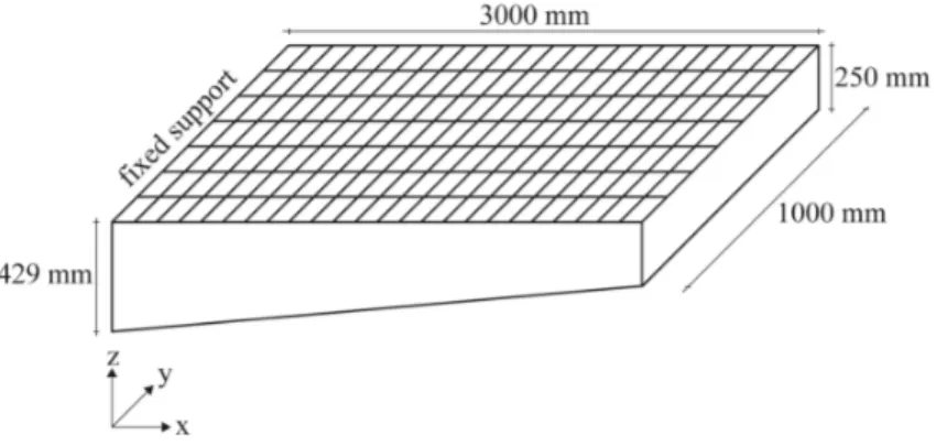
To illustrate the new concept, a one metre wide strip of a cantilever slab was analaysed (Fig. 6). Here, for simplicity and to limit computational cost, lCcrit = lCTCM was chosen. Furthermore, the tapering of the cantilever slab cross section towards the free end results in a decreasing size of the crack elements.
For simplicity the crack element size was assumed to be constant across the cantilever slab, such that the number of crack elements per tension chord (24) yielded integer values.
The limit state was defined as the ultimate limit state on characteristic level, consequently all forces were calculated on a characteristic level. The loads on the cantilever were the dead loads from the slab itself, a surcharge from a 10 cm asphalt cover and the live loads from road traffic according to the Swiss standard for actions on structures [16]. The resulting bending moments were converted to tensile forces by a strut-and-tie model. The tensile forces were assumed to be constant in each row of crack elements (y-direction, Fig. 6 and Fig. 7), and set to the tensile force that resulted from the strut-and-tie model in the middle of each crack element row. A homogeneous chloride exposure on the upper side of the slab was assumed. Once an element started corroding, a constant corrosion length β⋅lCTCM of 10 mm and a linear loss of 1 mm of the steel diameter per year (ζ) were assumed.
Fig. 7 shows snapshots of the cantilever slab after 3 years, where the first element started to corrode, 10 years, and 19 years, when the slab failed. The corresponding resistances and the tension chord force can be seen in Fig. 8 (left). The cross-sectional steel loss from Fig. 7 is reflected in the variation of the resistance in Fig. 8 (left). From the CTCM also the crack widths could be calculated (Fig. 8 (right)).
2nd CACRCS Workshop Capacity Assessment of Corroded Reinforced Concrete Structures
6
Fig. 6 Geometry of the analysed cantilever slab with a discretisation of 7 tension chords with 24 crack elements each.
year 3
year 10
year 19
Fig. 7 Model results for a 1 metre wide strip of a cantilever slab of 3 metres length that is devided in 7 tension chords and 24 rows (168 elements, top view). White elements are uncorroded.
Red gradient represents the loss of cross-sectional area of steel, where darker red implies a higher loss of steel cross-sectional area (ζ ∈ [0,1]).
behaviour
Deniz Yilmaz, Severin Haefliger, Walter Kaufmann, Ueli Angst 7 Fig. 8 (Left) Tension chord force and resistances for years 1, 5, 10, 15 and 19 (year of failure);
(right) crack widths along the cantilever slab after 1 and 15-19 years.
5 Outlook
Chapter 4 illustrated the application of the new conceptual approach to a relatively simple case. How- ever, there are still numerous aspects that have, so far, only been implemented rudimentarily, either for the purpose of a simple illustration or due to the lack of better knowledge.
The influence of cracks on chloride-induced corrosion, for example, is still discussed in the research community [17]. So far, no possible influence of the crack formation on the corrosion process was considered in the case study, but could be implemented in the future. When reaching a certain crack opening (resulting from the calculations of the CTCM, Fig. 8 (right)), the corrosion parameters, i.e. the corrosion length β⋅lCTCM and the evolution of the loss of steel cross-sectional area over time dζ/dt, may be adjusted to consider the mutual influence shown in Fig. 1. This implies that further research on the pit morphology and its evolution over time has to be conducted, as β and ζ are crucial input parameters for the CTCM.
For most practical applications, there is no homogeneous chloride load on structures. Therefore, the implementation of a heterogeneous chloride ingress is suggested. This would also imply that a finer mesh for the discretisation of the layer for the calculation of the corrosion probability may be needed.
Not only the layer for the calculation of the corrosion probability could be adjusted, but also the layer resulting from the CTCM for structural members with a variable cross section across the longitu- dinal axis, as the crack element size changes depending on the static height.
So far, statically determined structural members under tension and bending can be analysed. De- pending on the geometry and static system of the structural member, specific static models are required.
A planned extension of the approach is the adaption and implementation of the Cracked Membrane Model [18] to analyse structural members under in-plane stresses, e.g. the web of a bridge girder.
6 Conclusions
In this paper, we presented a new conceptual approach to model the service life of reinforced concrete structures in chloride exposure environments. The novelty is that this modelling concept considers both the corrosion process and the the load-deformation behaviour of the structure as well as their interrela- tions. This allows predicting the service life beyond the corrosion initiation stage (Fig. 2), because the time to reach clearly pre-defined limit states – such as critical deformations, crack openings, or reduc- tion in load carrying capacity – can be calculated with a stringent, fundamentally sound approach.
A key component of the proposed concept is to consider the stochastic nature of chloride-induced corrosion initiation and the relevance of the location of corrosion for the structural behaviour. Thus, this new conceptual approach not only considers the probability for corrosion, but also takes into ac- count the probability for corrosion to occur in a structurally critical location. This is important as it gives the predicted time to reach a limit state a clear physical meaning, and facilitates the interpretation of the outcome of probabilistic modelling at the level of decision takers (owners, consulting engineers),
2nd CACRCS Workshop Capacity Assessment of Corroded Reinforced Concrete Structures
8
in contrast to models where the service life prediction stops with corrosion initiation and where corro- sion is generally decoupled from the load-bearing behaviour of the structure.
References
[1] Angst, U., Elsener B., Larsen C.K., and Ø. Vennesland. 2009. “Critical chloride content in reinforced concrete - A review.” Cement and Concrete Research 39:1122–38, doi:
10.1016/j.cemconres.2009.08.006.
[2] Cao, Y., Gehlen, C., Angst, U., Wang, L., Wang, Z., and Y. Yao. 2019. “Critical chloride con- tent in reinforced concrete – An updated review considering Chinese experience.” Cement and Concrete Research 117:58–68, doi: 10.1016/j.cemconres.2018.11.020.
[3] Zhao, Z. and L. Fu. 2018 “The probability distribution of pitting for accelerated corrosion rein- forcement.”, Case Studies in Construction Materials 9:e00193, doi:
10.1016/j.cscm.2018.e00193.
[4] Andisheh, K., Scott, A., and A. Palermo. 2016. “Modeling the influence of pitting corrosion on the mechanical properties of steel reinforcement: Modeling the influence of pitting corrosion.”, Materials and Corrosion 67:1220–34, doi: 10.1002/maco.201508795.
[5] Val, D. V., and R. E. Melchers. 1997. “Reliability of Deteriorating RC Slab Bridges.”, Journal of Structural Engineering, 123:1638–44, doi: 10.1061/(ASCE)0733-9445(1997)123:12(1638).
[6] fib. 2013. fib Model Code for Concrete Structures 2010. Weinheim: Wiley-VCH Verlag.
[7] Bisschop, J., Schiegg, Y., and F. Hunkeler. 2016. Modelling the corrosion initiation of rein- forced concrete exposed to deicing salts. Bern: UVEK, Bundesamt für Strassen.
[8] Bentz, E. C., and M. D. A. Thomas. 2018. Life-365 service life prediction model and computer program for predicting the service life and life-cycle cost of reinforced concrete exposed to chlorides. Life-365 Consortium III.
[9] Stipanovic Oslakovic, I., Bjegovic, D., and D. Mikulic. 2010. “Evaluation of service life design models on concrete structures exposed to marine environment.” Mater Struct 43:1397–412, doi:
10.1617/s11527-010-9590-z.
[10] Luping, T. 2008. “Engineering expression of the ClinConc model for prediction of free and total chloride ingress in submerged marine concrete.” Cement and Concrete Research 38:1092–
97, doi: 10.1016/j.cemconres.2008.03.008.
[11] The European Union, Brite EuRam III. 2000. DuraCrete: final technical report, DuraCrete:
probabilistic performance based durability design of concrete structures, contract BRPR- CT95-0132, project BE95-1347, document BE95-1347/R17.
[12] Angst, U., Rønnquist, A., Elsener, B., Larsen, C. K., and Ø. Vennesland. 2011. “Probabilistic considerations on the effect of specimen size on the critical chloride content in reinforced con- crete.” Corrosion Science 53:177–87, doi: 10.1016/j.corsci.2010.09.017.
[13] Angst, U., and B. Elsener. 2017. “The size effect in corrosion greatly influences the predicted life span of concrete infrastructures.” Science Advances 3:e1700751, doi: 10.1126/sci- adv.1700751.
[14] Angst, U. 2018. “The importance of the size effect in corrosion of steel in concrete for proba- bilistic service life modeling.” in Life Cycle Analysis and Assessment in Civil Engineering:
Towards an Integrated Vision, Ghent:CRC Press, doi: https://doi.org/10.1201/9781315228914.
[15] Häfliger, S., Yilmaz, D., Angst, U., and W. Kaufmann. 2020. “Corroded Tension Chord Model (CTCM) for Concrete Structures with locally corroded reinforcement.” Paper presented at the CACRCS DAYS 2020 Capacity Assessment of Corroded Reinforced Concrete Structures, Online, December 1–4.
[16] Schweizerischer Ingenieur- und Architektenverein. 2014. SIA 261 – Einwirkungen auf Trag- werke. Zürich: Schweizerischer Ingenieur- und Architektenverein.
[17] Boschmann Käthler, C., Angst, U., Wagner, M., Larsen, C. K., and B. Elsener. 2017. “Effect of cracks on chlorideinduced corrosion of steel in concrete – a review” Oslo: Statens vegvesen.
https://vegvesen.brage.unit.no/vegvesen-xmlui/handle/11250/2625428.
[18] Kaufmann, W., and P. Marti. 1998. “Structural Concrete: Cracked Membrane Model.” Journal of Structural Engineering 124:1467–75, doi: 10.1061/(ASCE)0733-9445(1998)124:12(1467).