Temperature and pressure induced changes in the local atomic and electronic structure of
complex materials
Dissertation
zur Erlangung des Doktorgrades der Naturwissenschaften der Fakultät Physik der Technischen Universität Dortmund
vorgelegt von Christoph J. Sahle
November 2011
Contents
Contents iv
List of Figures v
List of Acronyms vii
1 Introduction 1
2 Theory of inelastic x-ray scattering 5
2.1 The double dierential scattering cross-section . . . . 5
2.1.1 X-ray absorption and the resonant term . . . . 9
2.1.2 The dynamic structure factor S(q, ω) . . . 12
2.2 Simulating XAS and XRS spectra from rst principles . . . 15
2.2.1 The real space multiple scattering formalism . . . 15
2.2.2 The nite dierence method to calculate σ
XAS(ω
1) . . . 17
2.2.3 The Kohn-Sham Density Functional Theory approach to XAS and XRS . . . 18
3 Experimental Setups 21 3.1 DELTA beamline BL8 . . . 21
3.2 ESRF beamline ID16 . . . 23
3.3 APS beamline 20-ID-B . . . 25
3.4 DELTA beamline BL9 . . . 25
4 Ge nanocrystal formation in oxide matrices 29 4.1 Phase separation and nanocrystal formation in bulk amorphous GeO
x. . . 31
4.2 Phase separation and size controlled growth of Ge nanocrystals in GeO/SiO
2multilayers . . . 38
4.3 Ge-oxide free Ge nanocrystal formation in multilayered GeSiO/SiO
2. . . . 45
4.4 Summary and outlook . . . 52
5 Ba intercalated Si clathrates 55 5.1 Modulations of the Ba GR in Si-Clathrates . . . 57
5.2 Pressure induced phase transitions in Ba
8Si
46. . . 67
5.3 Summary and outlook . . . 72
6 XRS studies of water and silicate melts under extreme conditions 75 6.1 Water at high temperature and high pressure . . . 76
6.2 Silicate melt NS3 at high temperature and high pressure . . . 86
6.3 Summary and outlook . . . 90
7 Summary and outlook 93
Supplement to chapter 6 i
Bibliography iii
List of publications xi
Acknowledgments xiii
Eidesstattliche Erklärung xiv
List of Figures
2.1 Schematic drawing of a typical inelastic scattering experiment . . . . 5
2.2 Feynman diagrams of the possible two-photon processes . . . . 8
2.3 Sketch of a RIXS process in a single particle picture . . . . 9
2.4 Example of a RIXS plane . . . 10
2.5 Cartoon of a scattering event of an emerging photo electron wave . . . 12
3.1 Schematic drawing of the beamline BL8 and photograph of the experimen- tal end-station . . . 22
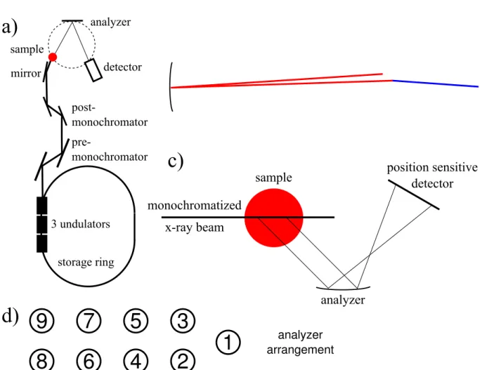
3.2 Schematic drawing of the inelastic scattering beamline and photograph of the experimental end-station at the ESRF beamline ID16 . . . 26
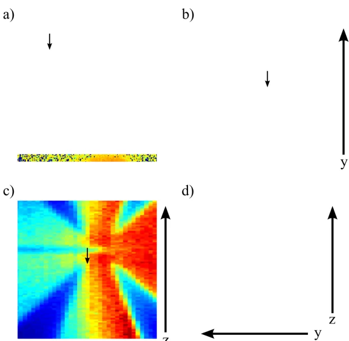
3.3 Illustration of the imaging properties of the spectrometer of the ESRF beamline ID16 . . . 27
3.4 Beamline 20-ID-B of Sector 20 of the APS . . . 28
4.1 Schematic drawing of the ICM model for bulk a-SiO . . . 31
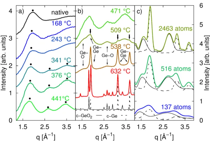
4.2 Temperature dependence of ex situ x-ray diraction data of bulk a-GeO . . 33
4.3 In situ XRD data of bulk a-GeO . . . 35
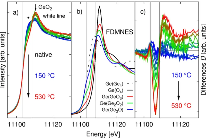
4.4 XANES spectra, simulations and dierences of in situ samples . . . 37
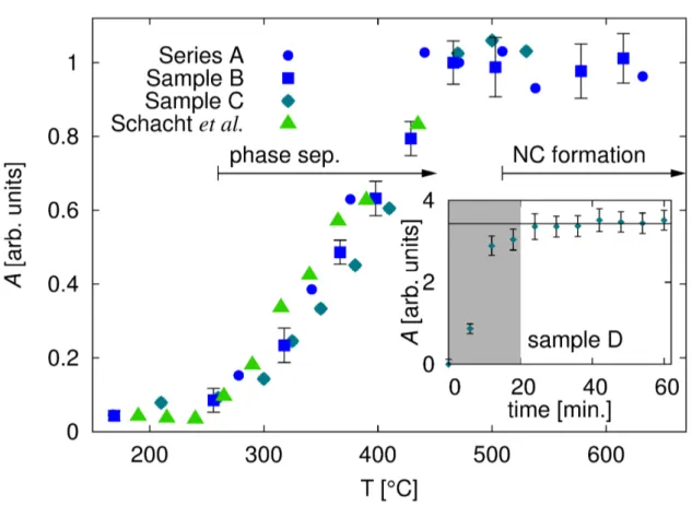
4.5 A(T ) of massive a-GeO samples . . . 39
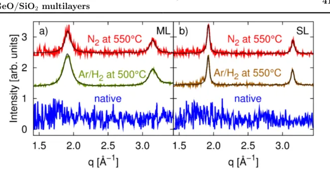
4.6 XRD patterns of multilayer samples . . . 41
4.7 TEM image of the annealed samples . . . 42
4.8 XANES spectra of multilayer samples . . . 44
4.9 A(T ) and Ge content fraction for GeO
x/SiO
2multilayer and thick GeO
xsamples . . . 46
4.10 XRD patterns of GeSiO
x/SiO
2multilayer samples . . . 48
4.11 XANES spectra of native and dierently annealed GeSiO/SiO
2multilayer samples . . . 49
4.12 XANES spectra and respective ts of the dierent SiGeO
x/SiO
2multilayer samples in their native state and after annealing . . . 50
4.13 Relative Ge content of samples A, B, and C for the dierent annealing temperatures . . . 51
5.1 Stick and ball plot of the structure of Ba
8Si
46, Ba
24Si
100, and BaSi
6and their constitutive Ba containing cages . . . 59
5.2 Experimental spectra and spectra calculated in the dipole limit using FEFF9 60 5.3 Inuence of nite momentum transfer on the shape of the Ba GR of Ba
8Si
46and Ba
24Si
100. . . 62
5.4 Dierences between spectra of the Ba GR for dierent momentum transfers and the dierent compounds Ba
8Si
46, BaSi
6, and Ba
24Si
100. . . 64
5.5 Calculated Ba GR spectra of dierent local Ba environments . . . 66
5.6 XRS spectra of the Ba N
4,5- and Si L
2,3-edges of Ba
8Si
46for pressures between 1.5 − 19.4 GPa , reference spectra of LaPO
4and CeO
2, and Si L
2,3- edge positions . . . 69 5.7 Pair distribution functions from RMC simulations of Ba
8Si
46for pressures
between 0.4 − 30.5 GPa . . . 70 5.8 Charge density contour plots of Ba
8Si
46in dierent relevant crystal planes
for selected pressures derived from a combined Rietveld/MEM analysis . . 72 6.1 Schematic drawing of the HDAC used and a series of images taken from
the sample in situ . . . 78 6.2 Phase diagram of water . . . 79 6.3 Experimental and simulated XRS spectra of water at high temperatures
and high pressures . . . 81 6.4 Radial distribution functions extracted from MD simulations . . . 83 6.5 XRS spectra of aqueous HCl solutions compared to pure water spectra for
dierent temperatures and pressures . . . 85 6.6 Si L
2,3-edge of dierent water bearing and water free silicate melts and
minerals and a rst in situ measurement of a hydrous silicate melt . . . 88
6.7 Simulated XRS spectra of crystalline NS3 and crystalline Albite . . . 89
7.1 Solutions to the equations of state of water after Wagner et al. . . . ii
List of Acronyms
a-GeO Amorphous germanium monoxide APS Advanced Photon Source
DAC Diamond anvil cell
DDSCS Double dierential scattering cross-section DELTA Dortmunder Elektronen Speicherring Anlage DFT Density functional theory
DOS Density of states
EDX Energy dispersive x-ray spectroscopy ESRF European Synchrotron Radiation Facility EXAFS Extended x-ray absorption ne structure FDM Finite dierence method
FMS Full multiple scattering FWHM Full width at half maximum
GGA Generalized gradient approximation GR Giant resonance
HDAC Hydrothermal diamond anvil cell H-bond Hydrogen-bond
ICM Interface clusters mixture (model) IXS Inelastic x-ray scattering
LDA Local density approximation
LERIX Lower energy resolution inelastic x-ray scattering spectrometer MEM Maximum Entropy Method
ML Multilayer
NC Nanocrystal
NRIXS Non-resonant inelastic x-ray scattering PFY Partial uorescence yield
PIPS Passivated Implanted Planar Silicon RBS Rutherford backscattering
RDF Radial distribution function
RIXS Resonant inelastic x-ray scattering RMC Reverse Monte Carlo (method) ROI Region of interest
RSMS Real space multiple scattering SDD Silicon drift detector
SL Singlelayer
TDLDA Time dependent local density approximation TEM Transmission electron microscopy
TFY Total uorescence yield
TPA Transition potential approximation XANES X-ray absorption near edge structure XAS X-ray absorption spectroscopy
XRD X-ray Diraction XRR X-ray reectivity
XRS X-ray Raman scattering
1 Introduction
Most macroscopic properties of material originate in its local atomic and electronic struc- ture. It is the understanding of these structures on the microscopic length scale and the interactions involved that drive condensed matter physicists. Manipulation of the local atomic and electronic structure may help develop new materials or modify properties of existing materials for dedicated demands. High temperature and pressure can induce changes in the local atomic and electronic structure; studies on these changes in complex materials are presented in this thesis. Questions raised from diverse elds such as ma- terials science and design, fundamental solid state physics, and the geosciences will be addressed.
Structural investigations on the atomic length scale are routinely performed for systems that exhibit long range order, e.g. using elastic x-ray or neutron scattering.
1In the case of disordered systems, however, this task turns out to be much more challenging and the measured quantities oftentimes only represent averages of the local structure over space and time. Here, the study of absorption edges was proven tremendously important to examine the local electronic and atomic structure even in disordered systems.
2In an x-ray absorption spectroscopy (XAS) experiment, the unoccupied density of electronic states is probed via the generation of a photoelectron from an inner core shell. This makes XAS an element selective probe since the electronic binding characteristics vary across the periodic table of elements. Measuring the unoccupied density of states provides details of the electronic structure of the investigated material and is sensitive especially to e.g. bond formation and changes in bonding.
3This also implies the indirectness of XAS as there is no direct correlation between spectral features and the atomic structure.
Usually structural information is extracted by comparison of spectral features to spectra of known materials or to simulated spectra of atomic models. However, even when the local structure cannot be revealed directly, XAS is very sensitive to structural changes.
For elements with electron binding energies in the hard x-ray regime, absorption edges can be measured bulk sensitively using XAS in uorescence or transmission mode. When interested in bulk properties of light elements, especially when studied under extreme conditions, however, XAS fails as probe due to the limited penetration depth of soft x- rays in matter. Here, x-ray Raman scattering (XRS)
4, an energy loss spectroscopy which provides similar information as XAS, with primary x-ray energies in the hard x-ray regime
1
Als-Nielsen, J. and McMorrow, D. (2011). Elements of modern X-ray physics. Wiley; Hurd, A.J. and Sinha, S. (2010). Neutrons & nanoscience (Neutron scattering applications & techniques). Springer.
2
Koningsberger, D.C. and Prins, R. (1987). X-ray absorption: principles, applications, techniques of EXAFS, SEXAFS and XANES. John Wiley and Sons Inc., New York, NY; Rehr, J.J. and Albers, R.C. (2000). Rev. Mod. Phys. 72, 621654.
3
Pylkkänen, T. (2011). Disordered matter studied by x-ray Raman scattering. PhD thesis. Univer- sity of Helsinki.
4
Schülke, W. (2007). Electron dynamics by inelastic X-ray scattering. Vol. 7. Oxford University Press,
USA.
can be used.
This thesis summarizes studies where x-ray spectroscopy is utilized to study the local structure as well as structural changes induced by elevated temperatures and/or pres- sure in dierent complex materials such as amorphous germanium and germanium-silicon oxides, barium clathrates, silicate glasses and melts, and supercritical water.
The thesis is organized as follows. Chapter 2 summarizes important relations from the theoretical framework of the techniques used. A short description of the program packages used to model absorption edges from rst principles is also given.
In chapter 3 a descriptive overview of the experimental endstations used is provided and the experimental details of the presented studies are summarized shortly.
A series of three studies of the phase separation and germanium nanocrystal forma- tion in oxide matrices is reported in chapter 4. The discovery of light emission from nanostructured silicon
5in the early 1990s attracted vast attention and gave rise to nu- merous studies of the properties of nanostructured semiconductors aiming at novel diverse and attractive applications such as new photoluminescent devices
6, fast and small non- volatile ash memory
7, and highly ecient photo-voltaic cells
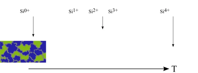
8. In this respect materials of nanocrystalline semiconductors especially silicon and germanium nanocrystals embedded in oxide matrices proved promising over e.g. porous silicon because of the high stability and durability of oxide matrix embedded nanocrystals. One of the production pathways for these oxide matrix embedded nanocrystals is the temperature induced phase separation of germanium monoxide which ultimately leads to the formation of nanocrystals. This temperature induced local atomic reordering was studied using XAS and x-ray diraction (XRD). Special attention is payed to the formation of size controlled nanocrystals in oxide matrices.
Chapter 5 summarizes the results of two studies aimed at the understanding of the pressure induced phase transitions in barium intercalated silicon clathrates. These com- plex cage-like structures exhibit numerous interesting physical properties like supercon- ductivity and thermoelectric behavior.
9The structural details and interactions between the intercalated guest atoms and the Si host network are of tremendous importance for the understanding of the mechanisms leading to the observed properties. In a rst inves- tigation the inuence of the local atomic environment of the Ba atoms on the Ba giant resonance
10is investigated using XRS and calculations employing a real space multiple scattering formalism. For the barium intercalated silicon clathrates Ba
8Si
46and Ba
24Si
100, several phase transitions without change in spacial symmetry were observed when high pressure is applied.
11This peculiar behavior still dees a unied explanation and a second study aimed at an understanding of the underlying mechanisms is also presented in this chapter.
5
Iyer, S.S. and Xie, Y.H. (1993). Science 260, 40.
6
Hirschman, K.D. et al. (1996). Nature 384, 338341; Godefroo, S. et al. (2008). Nature Nanotech.
3, 174178; Pavesi, L. et al. (2000). Nature 408, 440444.
7
Tiwari, S. et al. (1996). Appl. Phys. Lett. 68, 1377.
8
Conibeer, G. (2007). Mater. Today 10, 4250.
9
San-Miguel, A. and Toulemonde, P. (2005). High Pressure Res. 25, 159185.
10
Connerade, J.P. et al. (1987). Giant resonances in atoms, molecules, and solids.NATO ASIB Proc.
151: Giant Resonances in Atoms, Molecules, and Solids. Vol. 1.
11
San-Miguel, A. et al. (2002). Phys. Rev. B 65, 054109; Toulemonde, P. et al. (2011). Phys. Rev. B
83, 134110.
3 The inuence of high pressure and high temperature conditions on the local atomic environment of water and silicate melts was investigated using XRS and the results are summarized in chapter 6. High temperature and high pressure conditions give rise to structural reordering processes in the earth's interior. Numerous pressure induced phase transitions, such as the discontinuities found in the earth's mantle, are known to occur.
12Contrary to our intuitive perception, the earth needs to be viewed as a vibrant and dynamic system, most obviously witnessed through volcanism and earth quakes. For the geological processes in the earth's crust, water plays a key role. In subduction zones substantial amounts of water are dragged into the crust and upper mantle. High pressure and temperature conditions also lead to a considerable take up of water by silicate melts, a major constituent of the earth in these depths. The intake of water was shown to inuence physical and transport properties of these melts.
13First measurements aiming at the understanding of structural changes in silicate melts upon intake of water are also presented in this chapter.
The thesis concludes with a summary and outlook which is given in chapter 7.
12
Marshak, S. (2004). Essentials of geology. WW Norton.
13
Mysen, B.O. and Richet, P. (2005). Silicate glasses and melts: Properties and structure. Vol. 10.
2 Theory of inelastic x-ray scattering
In this chapter, an overview of the theoretical background of inelastic x-ray scattering (IXS) will be given. The physical quantity which is accessible in an IXS experiment, namely the double dierential scattering cross-section (DDSCS), will be derived from ba- sic principles of the interaction of x-rays with matter. Special attention will be payed to the aspects important for the experimental methods used in this thesis. In particular, non-resonant inelastic x-ray scattering (NRIXS) of core electrons, often referred to as non-resonant x-ray Raman scattering (XRS), and the resonant inelastic x-ray scattering (RIXS) process that enables one to measure an x-ray absorption edge using the uores- cence yield technique will be discussed in detail. In the remainder of this chapter, dierent approaches to calculate ab initio the cross-sections of the respective techniques will be presented shortly.
Figure 2.1: Schematic drawing of a typical inelastic scattering experiment. X-rays with wave vector k
1, energy ¯ hω
1and polarization e
1are scattered by the sample into wave vector k
2, energy ¯ hω
2and polarization e
2such that the energy ¯ hω = ¯ hω
1− ¯ hω
2and the momentum ¯ hq = ¯ hk
1− ¯ hk
2are transferred to the scattering system.
2.1 The double dierential scattering cross-section
The outline of a typical inelastic scattering experiment is given in Fig. 2.1. A monochro- matic x-ray beam of wave vector k
1, energy ¯ hω
1, and polarization e
1hits the sample, interacts with it and is scattered. During the interaction the system, characterized by its eigenstate |ii and eigenvalue E
i, can be excited into another state. The scattered radiation with wave vector k
2, energy ¯ hω
2, and polarization e
2is detected such that a scattering vector q is dened by the solid angle element of the detector Ω
2and the energy ¯ hω
2of the scattered radiation is analyzed. Since the transferred energy ¯ hω = ¯ hω
1− ¯ hω
2is usually small compared to the incident energy, the modulus of the transferred momentum is well approximated by
q = 2k
1sin(θ/2). (2.1)
In most inelastic scattering experiments, as is the case for the experiments carried out in the scope of this work, the polarization e
2of the scattered radiation is not analyzed.
In brief, the measured quantity of an IXS experiment is the double dierential scattering cross-section which can be described as
1d
2σ dΩ
2d¯ hω
2=
current of photons scattered into solid angle element [Ω
2, Ω
2+ dΩ
2] and into the range of energies [¯ hω
2, ¯ hω
2+ d¯ hω
2]
current density of the incident photons × dΩ
2× d¯ hω
2. (2.2) In what follows, the DDSCS shall be derived from basic principles of the interaction of x-rays with matter. Following Blume
2and thus Schülke
3, the derivation of the DDSCS starts with writing down the non-relativistic (to the order of (v/c)
2) Hamiltonian for a number of j electrons in a quantized electromagnetic eld:
H = 1 2m
X
j
p
j− e
c A(r
j)
2+ X
jj0
V(r
jj0)
− e¯ h 2mc
X
j
σ
j· ∇ × A(r
j) − e¯ h 4m
2c
2X
j
σ
j· E(r
j) × h p
j− e
c A(r
j) i + X
kλ
¯ hω
kc
+(kλ)c(kλ) + 1 2
.
(2.3)
Here, m is the electron mass, e the elementary electric charge, and c is the speed of light. c
+(kλ) and c(kλ) are the creation and annihilation operators and σ are the Pauli spin matrices. The rst term in (2.3) represents the kinetic energy of the electrons in the presence of the photon eld. Here, p
jis the j th electron's momentum operator, A(r
j) the operator of the vector potential of the electromagnetic eld at the position r
jof the j th electron. The second term corresponds to the potential energy of the interacting electron system. The third and fourth term are the potential energy of the magnetic moment which is connected with the electrons' spin in the magnetic eld of the radiation (∇ × A) and with (1/c)(v × E) , respectively. v is the electron's velocity which is to be understood in terms of its canonical momentum p . Since the magnetic structure of matter is not subject of interest in any of the experiments carried out in the scope of this thesis, spin dependent terms, i.e. those containing explicitly the vector potential A together with the Pauli spin matrices σ , will be omitted in what follows. However, the presence of these terms reveals the accessibility of magnetic properties by IXS. The last term of (2.3) is the energy of the photon eld. The summation over kλ is to be understood over all modes of the photon eld, where k is the wave vector and λ is counting the polarization directions.
1
Schülke, W. (2007). Electron dynamics by inelastic X-ray scattering. Vol. 7. Oxford University Press,
2
USA. Blume, M. (1985). J. Appl. Phys. 57, 36153618.
3
Schülke, W. (1991). Handbook on Synchrotron Radiation. Ed. by Brown, G. and Moncton, D.E.
Elsevier Science Publishers; Schülke, W. (2007). Electron dynamics by inelastic X-ray scattering.
Vol. 7. Oxford University Press, USA.
2.1 The double dierential scattering cross-section 7 Following Schülke
4, the vector potential A(r) is expressed in terms of the photon cre- ation and annihilation operators c
+(kλ) and c(kλ)
A(r) = s
2π¯ hc
2V ω
kX
kλ
[e(kλ)c(kλ) exp (ik · r − iω
kt) + e
∗(kλ)c
+(kλ) exp(−ik · r + iω
kt)],
(2.4)
using Coulomb gauge, introducing the scalar potential φ as in E = −∇φ − 1
c
A ˙ , (2.5)
and evaluating the square in the rst term of (2.3), one can isolate terms which represent the interaction between the photon eld and the electrons. These interaction terms will then be treated as a small perturbation within perturbation theory. The terms describing the interaction contain explicitly the vector potential A
H
i1= e
22mc
2X
j
A
2(r
j) (2.6)
and
H
i2= − e mc
X
j
A(r
j) · p
j. (2.7)
The remaining parts of the Hamiltonian that do not contain A are the Hamiltonian describing the interacting unperturbed electron system
H
0= 1 2m
X
j
p
2j+ X
jj0
V(r
jj0) + e¯ h 4m
2c
2X
j
σ
j· (∇φ × p
j) , (2.8) where the σ containing part is the spin-orbit coupling, and the Hamiltonian describing the radiation eld
H
R= X
k
¯ hω
kc
+(kλ)c(kλ) + 1 2
. (2.9)
The scattering processes described here are one and two photon processes and since the vector potential A (2.4) is linear in the creation and annihilation operators H
i1con- tributes to the inelastic scattering cross-section in rst order perturbation theory while H
i2will only contribute in second order perturbation theory. Using Fermi's golden rule, the DDSCS up to second order is given by
4
Schülke, W. (2007). Electron dynamics by inelastic X-ray scattering. Vol. 7. Oxford University Press,
USA.
d
2σ dΩ
2d¯ hω
2∝ 2π
¯ h
hf |H
i1|ii + X
n
hf |H
i2|ni hn|H
i2|ii (E
i− E
n)
2
δ(E
i− E
f). (2.10) The initial state |ii can be excited directly into the nal state |fi (rst term in (2.10)) or via an intermediate state |ni . This intermediate state |ni can be represented by either of the two Feynman diagrams depicted in Fig. 2.2. Thus, it may consist of a state where the incident photon has been annihilated rst (Fig. 2.2 a) |ni = |n, 0i or a state where the nal photon has been created rst |n, k
1λ
1, k
2λ
2i (Fig. 2.2 b)).
a) b)
Figure 2.2: Feynman diagrams of the possible two-photon processes which result from second order perturbation treatment of H
i2: a) intermediate state where the incident pho- ton has been annihilated rst and b) state where the nal photon has been created rst.
Evaluation of (2.10) yields for the DDSCS d
2σ
dΩ
2d¯ hω
2= e
2mc
2 2ω
2ω
1(e
1· e
∗2) hf | X
j
exp(iq · r
j)|ii
+ ¯ h
2m
X
n
X
jj0
hf |e
∗2· p
j/¯ h exp(−ik
2· r
j)|ni hn|e
1· p
j0/¯ h exp(ik
1· r
j0)|ii E
i− E
n+ ¯ hω
1− iΓ
n/2
+ hf |e
1· p
j/¯ h exp(ik
1· r
j)|ni hn|e
∗2· p
j0/¯ h exp(−ik
2· r
j0)|ii E
i− E
n− hω ¯
22
× δ(E
i− E
f+ ¯ hω).
(2.11) This is the well known Kramers-Heisenberg formula
5for the double dierential scattering cross-section. It contains, assuming relativistic eects are negligible up to the order of (v/c)
2, all information about the interaction of x-rays with matter. Here, Γ
nis the energy broadening due to a nite core-hole lifetime ( ¯ h/Γ
n) of the intermediate state |ni . Resonant and non-resonant inelastic scattering are described if |ii 6= |f i , for |ii ≡ |f i the Kramers- Heisenberg formula describes elastic scattering. The case for resonant and non-resonant x-ray scattering will be discussed in the next two sections.
5
Kramers, H.A. and Heisenberg, W. (1925). Z. Phys. A: Hadrons Nucl. 31, 681708.
2.1 The double dierential scattering cross-section 9
2.1.1 X-ray absorption and the resonant term
When ¯ hω
1≈ E
n− E
iholds for the incident photon energy, the second term in (2.11) becomes the dominant contribution to the DDSCS. This is referred to as the resonant case and the cross section reduces to
d
2σ dΩ
2d¯ hω
2= r
0m
2ω
2ω
1X
f
X
jj0
X
n
hf|e
∗2· p
jexp(−ik
2· r
j)|ni hn|e
1· p
j0exp(ik
1· r
j0)|ii E
i− E
n+ ¯ hω
1− iΓ
n/2
2
δ(E
i− E
f+ ¯ hω).
(2.12)
Here, r
0=
mce22denotes the classical electron radius. Equation (2.12) describes the coher- ent excitation of a tightly bound core electron from an initial state |ii into a short lived intermediate state |ni and de-excitation of this intermediate state into a nal state |f i . The adequate handling of the resonant denominator is taken care of by introducing the energy broadening of the resonance Γ
nwhich is, via the Heisenberg uncertainty principle, a consequence of the nite core-hole lifetime of the intermediate state.
Neglecting the coherence of excitation and de-excitation, this process may be sketched in a simplied single-particle picture as in Fig. 2.3 a). Part b) of the same gure illustrates the energy diagram for such a process.
1s22p64p0
1s12p64p1
1s22p54p1
a) b)
Figure 2.3: a) Sketch of a RIXS process in the single particle picture. |ii is the initial, |ni , and |fi are the intermediate and nal state, respectively. See text for details. b) Exemplary energy diagram for an excitation and de-excitation process as depicted in a).
The initial state consists of an incident photon (k
1, ¯ hω
1, e
1) and an electron in a bound core state ( |ii ). Depending on the energy of the incident photon and the symmetry of the initial state, the core electron is excited into either an unoccupied bound state or a free photo-electron state. This stresses how the unoccupied electronic states of the according symmetry are probed by the core-electron excitation. The intermediate state consists of a hole in a deep core state and an electron in a formerly unoccupied level.
In the de-excitation process, the intermediate state decays into the nal state by lling
the core hole with an electron from a bound state. Excitation and de-excitation have to obey the selection rules due to the conservation of angular momentum. In the hard x-ray regime this decay is mostly radiative and a photon with wave vector k
2, energy hω ¯
2, and polarization e
2is emitted. It is worth mentioning that, although the entire resonant scattering process has to satisfy energy conservation, the excitation process from the initial into the intermediate state is, due to the short lifetime (¯ h/Γ
n) of the intermediate state, not strictly limited by energy conservation
6.
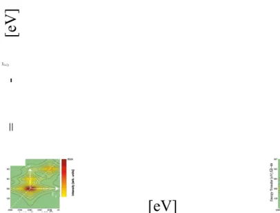
[eV] = -
[eV]
Figure 2.4: Calculated RIXS plane for a process as sketched in Fig. 2.3. Γ
Kand Γ
L,Mare the lifetime broadening of the K shell core hole and the nal state (hole in the L or M shell), respectively. Image taken from Glatzel, P. and Bergmann, U. (2005). Coord.
Chem. Rev. 249, 6595.
In a RIXS experiment, the energy transfer hω ¯ = ¯ hω
1− ¯ hω
2is measured for a variety of incident energies by an energy analysis of the emitted radiation. The information can be displayed in the so called RIXS plane, a two dimensional contour plot where the recorded intensity is plotted versus the energy transfer in one direction and the incident energy in the other. Such a theoretical RIXS plane taken from Glatzel et al.
7for a process as depicted in Fig. 2.3 is shown in Fig. 2.4, exemplarily. The energy broadening due to the nite K shell intermediate state (core hole) lifetime Γ
Kand the nite lifetime of the nal state, Γ
L,M, are shown as arrows in the horizontal (incident energy) and vertical (energy transfer) directions, respectively.
In many cases, recording the entire RIXS plane is tedious and/or even unnecessary.
As in this work, it is oftentimes sucient to monitor the intensity of an emission line while scanning the incident energy across the absorption edge. This is often referred to as partial uorescence yield (PFY) detection and, since the total intensity of an emission line is proportional to the absorption probability of x-rays, this is also referred to as x-ray absorption spectroscopy (XAS). Thus, in terms of inelastic x-ray scattering, a PFY-XAS
6
Schülke, W. (2007). Electron dynamics by inelastic X-ray scattering. Vol. 7. Oxford University Press,
7
USA. Glatzel, P. and Bergmann, U. (2005). Coord. Chem. Rev. 249, 6595.
2.1 The double dierential scattering cross-section 11 scan is equivalent to a diagonal cut through the RIXS plane as hω ¯
2is xed. In PFY, the RIXS cross section reduces to a function of the incident energy ¯ hω
1at a xed value of
¯
hω
2. Setting E
f+ ¯ hω
2= E
n, and thus xing ¯ hω
2to the maximum of the uorescence line, the cross section can be written as
8σ
PFY(ω
1) ∝ X
n
|hn|T |ii|
2×
1
(E
i− E
n+ ¯ hω
1)
2+ Γ
2n/4
Γ
f/π
(E
n− E
i− ¯ hω
1)
2+ Γ
2f/4
.
(2.13)
The transition operator of the excitation process in (2.12) has been replaced by T for simplicity. In the dipole limit T reduces to ( e
1· r) . Compared to the full RIXS equation (2.12) the transition matrix element hf|T
+|ni is independent of the incident photon energy and since only one nal state has to be considered (xed ¯ hω
2), the summation over f can be omitted. The energy conserving δ -function was represented by a Lorentzian with full width at half maximum Γ
f. This accounts for the nite lifetime of the nal state. Equation (2.13) again stresses the sensibility of XAS to the unoccupied density of states (uDOS) since absorption is only possible for suitable unoccupied states |ni .
In an even more rigorous approach, the total uorescence yield (TFY) which corre- sponds to an energy integration over ¯ hω
2is monitored e.g. by a simple pin diode detector which simplies the experimental setup substantially. In case of TFY, the probability that an electron is excited from an initial into an intermediate state is given by
σ
TFY(ω
1) ∝ X
n
|hn|e
1· r|ii|
2δ(E
n− E
i− ¯ hω
1). (2.14) To bring (2.14) into the form of (2.13) the δ -function can also be broadened into a Lorentzian
σ
TFY(ω
1) ∝ X
n
|hn|T |ii|
2(Γ
n/2π)
(E
n− E
i− hω ¯
1)
2+ Γ
2n/4 . (2.15) Comparing (2.13) with (2.15), the PFY spectrum appears similar to the TFY, but with a spectral broadening that stems from the lifetime of the intermediate state as compared to the nal state. Since the lifetime of the intermediate state h/Γ ¯
nis usually smaller than that of the nal state ¯ h/Γ
f, RIXS allows one to investigate absorption edges with a resolution higher than in uorescence or transmission XAS. In the example of Fig. 2.4 the energy broadening due to the lifetime of the 1s core-hole is responsible for the maximum energy resolution in TFY. In PFY, however, the energy broadening due to the lifetime of the hole in the 2p state will limit the maximum energy resolution. The 2p state is more weakly bound than the 1s state and the lifetime of a hole in a 2p state is usually longer than for a 1s core-hole. Since the lifetime is, via Heisenberg's uncertainty principle, inverse proportional to the energy broadening, PFY yields a higher resolution than TFY.
8
Schülke, W. (2007). Electron dynamics by inelastic X-ray scattering. Vol. 7. Oxford University Press,
USA.
This was rst shown by Hämäläinen et al.
9for the case of the Dysprosium L
3-edge.
Besides this electronic picture of XAS, it is oftentimes instructive to view the explicit form of an absorption edge as a result of a multiple scattering event of the photo-electron wave at the atoms surrounding the absorbing atom. The shape of the absorption edge is then modulated by the interference of the outgoing and backscattered photo-electron wave.
10This multiple scattering event is depicted in Fig. 2.5 and demonstrates the sen- sitivity of absorption spectroscopy to the immediate surrounding of the absorber. In the direct vicinity of an absorption edge, the photo-electron has little kinetic energy and mul- tiple scattering is strong. This region extends to a few 10 eV above an absorption edge and is often referred to as x-ray absorption near edge structure (XANES). XANES spec- troscopy is thus sensitive to the exact shape of the scattering potentials, i.e. coordination chemistry, bond length and bond angles. Far above an absorption edge single scattering dominates as the photo-electron has higher kinetic energy. The region beyond the XANES region is called extended x-ray absorption ne structure (EXAFS). EXAFS spectroscopy yields information like next neighbor distances, angles, and coordination numbers.
11absorbing atom
outgoing photo-electron scattered
photo-electron scattering
atom
Figure 2.5: Cartoon of an emerging photo electron wave that scatters o of neighboring atoms.
Interference of the emerging and backscattered photo electron wave modulate the absorption probability.
2.1.2 The dynamic structure factor S(q, ω)
The rst term in (2.11) describes non-resonant (inelastic) scattering. When the incident energy hω ¯
1is far away from the binding energy of an inner shell electron, the terms including an intermediate state |ni in (2.10) are certainly small and can be neglected. In this case, only the term in the interaction Hamiltonian that is quadratic in the vector potential A contributes to the DDSCS and (2.10) can be simplied and rewritten as
d
2σ dΩ
2d¯ hω
2= r
20ω
2ω
1|e
1· e
∗2|
2hf| X
j
e
iq·
rj|ii
2
δ(E
i− E
f− ¯ hω). (2.16)
9
Hämäläinen, K. et al. (1991). Phys. Rev. Lett. 67, 28502853.
10
Rehr, J.J. and Albers, R.C. (2000). Rev. Mod. Phys. 72, 621654.
11
For more information about x-ray absorption spectroscopy (XAS) the reader is referred to Konings-
berger et al. (Koningsberger, D.C. and Prins, R. [1987]. X-ray absorption: principles, applications,
techniques of EXAFS, SEXAFS and XANES. John Wiley and Sons Inc., New York, NY) and Rehr
et al. (Rehr, J.J. and Albers, R.C. [2000]. Rev. Mod. Phys. 72, 621654).
2.1 The double dierential scattering cross-section 13 Usually (2.16) is written as
d
2σ dΩ
2d¯ hω
2=
dσ dΩ
2Th
S(q, ω), (2.17)
with the Thomson scattering cross-section which describes the photon-electron coupling dσ
dΩ
2Th
= r
20ω
2ω
1|e
1· e
∗2|
2, (2.18) and the dynamic structure factor
S(q, ω) =
hf| X
j
e
iq·
rj|ii
2
δ(E
i− E
f+ ¯ hω). (2.19) The delta-function ensures energy conservation.
In principle, S(q, ω) contains all information about the sample as an interacting many electron system by non-resonant scattering. Equation (2.19) stresses the inelastic scat- tering process as an electronic excitation from a ground state |ii to an excited state |f i . Likewise, S(q, ω) can be expressed as a time dependent electron density uctuation in the ground state
S(q, ω) = 1 2π¯ h
Z
∞−∞
dte
−iωthi| X
jj0
e
−iq·
rj0(t)e
iq·
rj(0)|ii . (2.20) This formulation was rst derived by van Hove
12and q
−1and ω
−1determine the length and time scales probed. In yet another formulation, S(q, ω) can be related to the inverse of the dielectric function (q, ω)
S(q, ω) = (1 + η
B) q
2¯ h 4πe
2Im
−1 (q, ω)
, (2.21)
where η
Bis the Bose factor. Depending on the amount of energy and/or momentum transfered to the electron system, certain representations may be more intuitive than others. Thus, according to Schülke (2007), the dierent NRIXS experiments can be classied with respect to the information drawn from the experiment:
1. Valence electron excitations with qr
c≈ 1 and ω ≈ ω
pwhere the characteristic length r
cis the inter-particle distance and ω
pthe plasmon frequency.
2. Scattering by inner-shell excitations or XRS with ¯ hω ≈ E
Band qa ≤ 1 where E
Bis the binding energy of an inner shell electron and a its orbital radius.
3. Phonon excitations with qd ≈ 1 and ω ≈ ω
phwhere d is the inter-ionic distance and ω
phis the phonon frequency.
12
Hove, L. Van (1954). Phys. Rev. 95,1, 249262.
4. Compton scattering with qr
c1 and ¯ hω E
0, where E
0is a characteristic energy of the system.
Only XRS was used in this work and thus formulation (2.19) is the most convenient rep- resentation for S(q, ω) , for details of all other techniques the reader will be referred to the according literature (see Schülke
13and references therein for a comprehensive overview).
Since in XRS the momentum transfer q is small, the transition operator in (2.19) can be expanded in a Taylor series
hf |e
iq·
r|ii = i hf |q · r|ii − 1
2 hf|(q · r)
2|ii + O((q · r)
3). (2.22) The zeroth order term vanishes due to the orthogonality of initial and nal state. The rst term in the Taylor series describes dipole transitions and dominates for small q . Here, the analogy of XRS and XAS, where only dipole transitions are allowed, becomes obvious.
14In the single particle approximation the momentum transfer q in XRS takes over the role of the polarization e
1of the incident x-ray beam in XAS
σ
XAS(ω
1) ∝ | hf |e
1· r|ii |
2δ(E
i− E
f+ ¯ hω
1), (2.23) S(q, ω) = | hf|q · r|ii |
2δ(E
i− E
f+ ¯ hω). (2.24) Thus, the information content of S(q, ω) in the dipole limit and when ¯ hω ≈ E
Bis formally the same as in XAS where hω ¯
1≈ E
B. However, since the energy loss ω does not depend on the incident energy, the incident energy can be chosen freely. Mostly, ¯ hω
1in an XRS experiment is of the order of 10 keV whereas the energy transfer is of the order of typical binding energies of low Z elements. This is a tremendous advantage of XRS when studying low Z absorption edges bulk sensitively and/or under extreme conditions and complicated sample environments that do not allow soft x-rays or electrons as probe. The drawback, however, is the small cross section of XRS compared to XAS such that XRS experiments are feasible only at dedicated experimental end-stations at 3rd generation synchrotron radiation sources.
15For higher momentum transfers, higher order terms in the Taylor series (2.22) contribute more signicantly to S(q, ω) and thus, the study of multipole-transitions becomes feasible.
The fact that also dipole forbidden transitions are accessible with XRS makes it sensible to the entire uDOS.
1613
Schülke, W. (2007). Electron dynamics by inelastic X-ray scattering. Vol. 7. Oxford University Press,
14
USA. Mizuno, Y. and Ohmura, Y. (1967). J. Phys. Soc. Jpn. 22,2, 445449.
15
An overview of the dierent experimental requirements needed and experimental setups used is given in chapter 3.
16
Soininen, J.A. et al. (2005). Phys. Rev. B 72, 045136.
2.2 Simulating XAS and XRS spectra from rst principles 15
2.2 Simulating XAS and XRS spectra from rst principles
The direct interpretation of XAS and XRS spectra is not straightforward and the analysis is either qualitative using the evolution of spectra with the variation of an experimental parameter or quantitative by comparison to reference spectra, if these are available. A dierent approach is to model the electronic structure of an atomic conguration and calculate from this the XAS or XRS spectra from rst principles. Assuming the com- putational method gives accurate results, this provides a direct access to a structural model by comparison of the calculated and experimental spectra. In what follows, the three computational approaches used in the scope of this work shall be introduced and described shortly from an experimentalist's point of view. In particular, the program package FEFF, which allows the calculation of both XAS and XRS spectra, is described in section 2.2.1. The program package FDMNES, which can be used to calculate XAS spectra, is presented in section 2.2.2, and a short introduction to density functional theory, which is used by the StoBe-deMon program package, is given in section 2.2.3.
2.2.1 The real space multiple scattering formalism
The perception of the ne structure in XAS as a result of multiple scattering of the emerg- ing photo-electron wave provides a convenient basis for the ab initio calculation of XAS and XRS spectra. This approach is called real-space multiple-scattering (RSMS) formal- ism and is implemented in the FEFF
17program package
18. The calculations are based on the fact that Fermi's golden rule (equations (2.15) and (2.19)) can be reformulated using a single-particle Green's function G as in
−(1/π) Im G = X
f
|f i hf | δ(E − E
f). (2.25) For the case of XAS and XRS, the golden rule then becomes
19σ(E) ∝ − 2
π Im hi|e · r
0G(r
0, r, E)e · r|ii (2.26) and
S(q, ω) ∝ − 2
π Im hi|e
−iq·
r0G(r
0, r, E)e
iq·
r|ii . (2.27) Since the computation of the nal state wave function |fi is usually challenging because it needs to be calculated in the presence of a (possibly) screened core hole, one apparent advantage of this formulation is that |f i does not appear explicitly in equation (2.26). In-
17
The name FEFF stems from the eective scattering amplitude
feffintroduced by Rehr et al. (Rehr, J.J. and Albers, R.C. (1990). Phys. Rev. B 41, 8139). Within this thesis the program package FEFF9 was used to calculate absorption edges, the program package FEFFq was utilized for all q dependent XRS calculations.
18
Rehr, J.J. et al. (2010). Phys. Chem. Chem. Phys. 12, 55035513.
19
Ankudinov, A.L. et al. (1998). Phys. Rev. B 58, 7565; Soininen, J.A. et al. (2005). Phys. Rev. B 72,
045136.
stead, the one-electron Green's function G = (E −H +iΓ)
−1with the eective one-electron Hamiltonian H = H
0+ P
n
v
nand the photo-electron energy E needs to be calculated.
This eective one-electron Hamiltonian H is given by the free electron Hamiltonian H
0and the scattering potentials v
nat the according atomic site n within a nite cluster
20. Within the program package FEFF, the atomic scattering potentials v
nare approximated by mun tin potentials which are calculated self consistently (self consistent eld (SCF) method) by iterating the total electron density, the potential, and the Fermi energy.
21The Green's function G
L0R0,LR, i.e. the amplitude for an electron to propagate from a state
|LRi into state |L
0R
0i , where R denotes the site and L = (l, m) the angular momentum, can be calculated as
G = G
c+ G
sc. (2.28)
G
crepresents the contribution from the central atom (−1/π) Im G
c= δ
R,R0δ
L,L0and G
scdenotes the scattering from the surrounding atoms which, using the free propagator G
0, is given by the implicit functional Dyson equation
G
sc= G
0tG
0+ G
0tG
0tG
0+ · · · . (2.29) Here, t is the scattering matrix and scattering from all single scattering paths ( G
0tG
0), double scattering paths ( G
0tG
0tG
0), etc. are summed up. In many cases, this so called path expansion converges well, especially at high photo-electron energies
22, and (2.29) can be truncated after a nite number of paths. At low photo-electron energies
23, however, multiple scattering is strong and it may be necessary to include all scattering paths. This is accounted for by calculating the full multiple scattering (FMS) using
G
sc= (1 − G
0t)
−1G
0, (2.30)
which involves a numerically challenging matrix inversion. However, since the mean free path of the photo-electron in the vicinity of an absorption edge, i.e. where the path expansion fails, is of the order of 1 − 5 Å, only a relatively small cluster with the order of 10
2atoms needs to be taken into account.
For the calculation of inelastic x-ray scattering cross sections, i.e. XRS spectra, the momentum transfer q has to be considered. In order to nd the weights of the various excitation channels, the nal state density matrix is represented in an angular momentum ( L = l, m ) and site R basis |L, Ri and rewriting S(q, ω) gives
S(q, ω) = X
LL0
M
L(−q, E)ρ
LL0(E)M
L0(q, E). (2.31) Here, M
L(q, E) = hR
L(E)|e
iq·
r|ii are the atomic transition matrix elements describing the transition from initial states |ii into exited states with energy E = E
i+ ¯ hω and L - type angular momentum. The empty states are described by the matrix elements ρ
LL0(E )
20
This bears the advantage of being able to account for periodic and aperiodic systems alike.
21
Soininen, J.A. et al. (2005). Phys. Rev. B 72, 045136.
22
I.e. the EXAFS regime.
23
I.e. the XANES region.
2.2 Simulating XAS and XRS spectra from rst principles 17 of the nal states density matrix.
24In polycrystalline materials or materials with cubic symmetry, equation (2.31) can be simplied to
S(q, ω) = X
l
(2l + 1) |M
l(q, E)|
2ρ
l(E). (2.32) Since the matrix elements M
l(q, E) are inherently atomic properties, they can be calcu- lated reliably by the FEFF program package, and the l DOS is extractable directly by measuring S(q, ω) parametrically for several values of q and solving equation (2.32).
252.2.2 The nite dierence method to calculate σ
XAS(ω
1)
A drawback of the ab initio calculation scheme used by FEFF is the rather rudimen- tary approximation of the atomic scattering potentials by mun-tin like potentials. As mentioned earlier in most cases the exact form and shape of the scattering potentials is not essential and remarkable agreement can be achieved between experiment and the Green's function approach described in section 2.2.1. This holds especially far above the absorption edge onset, i.e. in the EXAFS regime, where the interaction between the photo-electron and the scattering potentials is weak. In the direct vicinity of an absorp- tion edge where the interaction of photo-electron and the scattering potentials is strong, however, the mun-tin approximation may fail and the use of a more realistic scattering potential is inevitable.
The initial state is usually an atomic core orbital and can be calculated straightfor- wardly whereas the computation of the nal state is quite demanding. Instead of using the Green's function formalism described in section 2.2.1 which uses the mun tin ap- proximation for the atomic scattering potentials, the program package FDMNES uses the nite dierence method (FDM)
26to solve the Schrödinger equation for the wave func- tions. This is performed on a discretized three dimensional grid in real space and the unknowns are the values of the wave function at each of the grid points in a spherical volume around an absorbing atom.
27As potentials a superposition of atomic densities are used as a starting point for a self consistent eld iteration similar to the case in the FEFF program package. The Coulomb potential is calculated from the densities via Poisson's equation and a Hedin-Lundqvist type exchange-correlation potential
28is accounted for.
If the core hole-photo-electron interaction is small, i.e. the core hole is screened well, elec- tronic densities, as calculated from ground state band structure programs, can be used as input for FDMNES.
A considerable drawback of the FDM approach for calculating absorption edges is the numerically expensive calculation of the nal states despite the discretization. This limits the applicability of this method to relatively small clusters and the near edge features.
However, since the exact shape of the scattering potentials is less important far away from an absorption edge, calculations using the mun tin approximation are well suited for this task. Up to date, a nite momentum transfer, as needed for the calculation of XRS
24
Soininen, J.A. et al. (2005). Phys. Rev. B 72, 045136.
25
Soininen, J.A. et al. (2005). Phys. Rev. B 72, 045136.
26
Kimball, G.E. and Shortley, G.H. (1934). Phys. Rev. 45, 815.
27
Joly, Y. (2001). Phys. Rev. B 63, 125120.
28
Hedin, L. and Lundqvist, B.I. (1971). J. Phys. C: Solid State Phys. 4, 2064.
spectra, cannot be accounted for within the FDMNES program package.
2.2.3 The Kohn-Sham Density Functional Theory approach to XAS and XRS
A very dierent approach than described in the last two sections is based on the famous density functional theory (DFT)
29. It is based on the fact, that the energy of a many particle wave function |Ψi can be calculated as
E{|Ψi} = hΨ|H|Ψi
hΨ|Ψi , (2.33)
and each wave function is linked to a density ρ(r) = hΨ| X
i
δ(r − r
i)|Ψi . (2.34)
Hohenberg and Kohn showed
30that there exists a ground state density ρ
0(r) which uniquely minimizes this functional, i.e. the density ρ
0(r) , for which the functional
E{ρ(r)} = hΨ|H|Ψi (2.35)
is minimal, is the ground state density and the according value of the functional E
0= E{ρ
0(r)} is the ground state energy of the system. Thus, instead of trying to solve the Schrödinger equation for a system of N interacting particles, one has to nd a density (in three spatial dimensions) which minimizes the functional (2.35). This leads to the variational problem
δE{ρ(r)} = 0, (2.36)
for which Kohn and Sham have introduced a procedure that leads to the Kohn-Sham equations
31− ¯ h
22m ∇ + V
eff(r)
ψ
i(r) =
iψ
i(r), (2.37) with the Kohn-Sham orbitals ψ
i(r) , their eigenvalues
i, and the eective single-particle potential
V
eff(r) = V (r) + Z
dr
0e
2|r − r
0| ρ(r
0) + δE
xc{ρ(r)}
δρ(r) . (2.38)
Here, V (r) is the external potential, e.g. of the nuclei, R
dr
0|r−re20|ρ(r
0) the classical electro- static interaction between the electrons, and V
xc(r) = δE
xc{ρ(r)}/δρ(r) the exchange-
29
A detailed and comprehensive introduction to DFT is, e.g., given by Fiolhais, C. et al. (2003). A primer in density functional theory. Vol. 620. Springer Verlag.
30
Hohenberg, P. and Kohn, W. (1964). Phys. Rev. 136, B864.
31
Kohn, W. and Sham, L.J. (1965). Phys. Rev. 140, 11331138.
2.2 Simulating XAS and XRS spectra from rst principles 19 correlation potential which contains all many body quantum mechanical eects. Thus, the Kohn-Sham equations describe non-interacting electrons in an eective potential, where all many-body eects are accounted for by an eective potential V
eff(r) . Since the unknown density ρ(r) = P
i
|ψ
i(r)|
2is itself a factor in the eective potential, (2.37) has to be solved self consistently. The exchange-correlation potential is also generally unknown and thus has to be approximated, however, a considerable number of approximations exist.
32Although the Kohn-Sham orbitals ψ
i(r) are only used to construct the density ρ(r) and thus have no direct physical meaning, they are often used as approximations to the actual single particle wave functions. Using the StoBe-deMon code
33equations (2.37) can be solved self-consistently for a small cluster of atoms and the resulting Kohn-Sham orbitals and their energies can be used to calculate XAS and XRS spectra via equations (2.23) and (2.24), respectively. As pointed out in sections 2.2.1 and 2.2.2, the nal state has to be calculated in the presence of a core hole. This is circumvented using the transition potential approximation (TPA)
34to the transition state approach by Slater
35. Within the TPA, the initial and nal states are calculated at the same time with a half core hole in the initial state and a half core hole in the nal state. As a starting point for the iterative calculation of the Kohn-Sham orbitals, the StoBe-deMon code uses a linear combination of Gaussian type orbitals to solve the Kohn-Sham equations. A number of approxima- tions to the exchange-correlation interaction potential like the local density approximation (LDA) and several parametrizations of the generalized gradient approximation (GGA) are implemented. In case there are several equivalent absorbing atoms in the atomic cluster, model core potentials can be used for all non-excited atoms of the same kind to ensure the localization of the core hole. The calculation of x-ray absorption spectra is readily included in the StoBe-deMon program package. The computation of XRS spectra was re- cently described by Sakko et al.
36. For all practical comparisons to experimental data, the calculated spectra have to be broadened to mimic experimental and lifetime broadening as well as the continuum part of the spectra. This is usually achieved by convolution of the calculated spectra with a Gaussian or Lorentzian with energy dependent full width at half maximum (FWHM).
3732
Fiolhais, C. et al. (2003). A primer in density functional theory. Vol. 620. Springer Verlag.
33
Hermann, K. et al. http://w3.rz-berlin.mpg.de/hermann/StoBe/index.html.
34
Triguero, L. et al. (1998). Phys. Rev. B 58, 8097.
35
Slater, J.C. and Johnson, K.H. (1972). Phys. Rev. B 5, 844.
36
Sakko, A. et al. (2007). Phys. Rev. B 76, 205115.
37
Leetmaa, M. et al. (2010). J. Electron. Spectrosc. Relat. Phenom. 177, 135157; Hetenyi, B. et al.
(2004). J. Chem. Phys. 2004, 120.
3 Experimental Setups
The experiments presented in this thesis were all carried out using hard x-rays with photon energies of the order of 10 keV . Since an x-ray source which allows tuning the x-ray energy combined with a high photon ux is necessary for absorption spectroscopy and inelastic x-ray scattering experiments, all experiments were carried out at synchrotron radiation facilities. The experimental setups used will be described in this chapter. All x- ray absorption spectroscopy experiments were performed at the DELTA
1beamline BL8.
The setup of this beamline will be described rst. Due to the small cross section for non-resonant inelastic x-ray scattering, all XRS experiments were carried out at the third generation synchrotron radiation facilities ESRF
2and APS
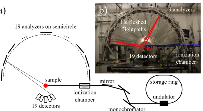
3. The unique setup of beamline ID16 (ESRF) for inelastic x-ray scattering allows experiments under extreme conditions like high temperatures and high pressures and will be described in section 3.2. In section 3.3 the IXS beamline 20-ID-B at the APS will be introduced. This beamline provides an exceptional setup to measure a large range of momentum transfers simultaneously. In the last section of this chapter, the XRD setup of the DELTA beamline BL9 is presented shortly.
3.1 DELTA beamline BL8
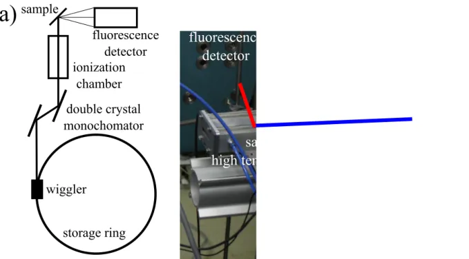
The general outline of the materials science beamline BL8
4of the 1.5 GeV storage ring DELTA is depicted in a schematic drawing in Fig. 3.1 a). A photograph of the experimen- tal end-station is provided in Fig. 3.1 b). Beamline BL8 is the rst of three beamlines that are supplied with synchrotron radiation from a 5.3 T asymmetric wiggler. The radiation is monochromatized by a Si(111) double crystal monochromator and can be collimated using slits. Typically, spot sizes on the sample were chosen to be 1 × 3 mm
2(V × H).
In order to measure the incident photon ux on the sample, the monochromatic x- ray beam passes through an argon lled ionization chamber and a photo-ion current proportional to the incident photon ux was used to normalize the data in all experiments.
The absorption cross section is proportional to the uorescence
5intensity which was detected by three uorescence detectors. Here, a Canberra Passivated Implanted Planar Silicon (PIPS) diode and two Amptek silicon drift diode (SDD) detectors were employed.
The PIPS detector measures the total uorescence yield, whereas the SDD detectors can measure energy dispersively such that the intensity of a single emission line
6can
1
Dortmunder Elektronen Speicherring Anlage, Dortmund, Germany.
2
European Synchrotron Radiation Facility, Grenoble, France.
3
Advanced Photon Source at the Argonne National Laboratories, Argonne, USA.
4
Lützenkirchen-Hecht, D. et al. (2009). J. Synchrotron Rad. 16, 264272.
5 σ(E)∝If/I0
, where
I0is the incident and
Ifthe uorescence intensity, respectively.
6
In all experiments, the Ge K
α1was monitored; the energy resolution of the SDD detectors is of the
order of 150 eV.
ionization chamber
fluorescence detector
double crystal monochomator sample
storage ring wiggler
a)
ionization chamber
sample in high temperature cell fluorescence
detector
b)
Figure 3.1: a) Schematic drawing of the DELTA beamline BL8 with the most important compo- nents and b) photograph of the experimental end-station with a high temperature in situ sample cell mounted on the sample stage. Incoming beam and the uorescence radiation are indicated by a blue and red line, respectively.
be monitored. To suppress undesired elastic and Compton scattering, the uorescence detectors are ideally placed at an angle of 90
◦to the incident beam in the horizontal plane.
In the experiments carried out at the DELTA beamline BL8, the Ge K-edge of bulk amorphous GeO, GeO/SiO
2multilayers, and GeSiO/SiO
2multilayers were measured by scanning the incident energy between 10.988 a nd 11.148 eV and detecting the uorescence yield using both the energy dispersive SDD detectors and the PIPS detector. The SDD detectors were calibrated to measure the intensity of the Ge K
α1uorescence line. Ex- periments were carried out in and ex situ. The in situ experiments were conducted using a custom built high temperature sample cell
7(see Fig. 3.1 b)). Prior to the experiments the sample cell was evacuated and ushed with inert gas at a steady ow rate during the in situ annealing processes. Samples annealed ex situ were measured in the same geom- etry using an appropriate sample holder. Several XANES scans of each sample at each temperature were measured, checked for consistency, and summed up. For comparison all resulting spectra were normalized to their integral intensity in the same energy range.
7