FACHBEREICH INFORMATIK
Sony Legged League
Virtual Robot: Automatic Analysis of Situations and Management of
Resources in a Team of Soccer Robots.
PG 442
Students: Damien Deom, J¨orn Hamerla, Mathias H¨ulsbusch, Jochen Kerdels, Thomas Kindler, Hyung-Won Koh, Tim Lohmann, Manuel Neubach,
Claudius Rink, Andreas Rossbacher, Frank Roßdeutscher, Bernd Schmidt, Carsten Schumann,
Pascal Serwe
Supervisors: Ingo Dahm, Matthias Hebbel, Walter Nistico, Christoph Richter, Dr. Jens Ziegler
September 2004
FINAL REPORT
Lehrstuhl f¨ur Systemanalyse Fachbereich Informatik der Universit¨at Dortmund
Computer Engineering Institute Fachbereich Elektrotechnik der Universit¨at Dortmund
S Sy
Figure 2: .. and the technology behind it.
1 The picture shows Muffit, a character from the Battlestar Galactica TV series. NBC, 1978-80.
Contents
1 Introduction 4
1.1 Overview of the RoboCup . . . . 4
1.2 Overview of the project group . . . . 5
2 Basics 6 2.1 Rules of the games . . . . 6
2.2 API and operating system . . . . 6
2.2.1 Aperios . . . . 7
2.2.2 Open-R . . . . 7
2.2.3 GT2004 . . . . 8
2.3 GermanTeam software architecture . . . . 8
2.3.1 Process framework . . . . 8
2.3.2 Module concept . . . . 9
2.4 RobotControl . . . 10
2.5 Main focus of the GermanTeam . . . 11
3 Tuning for the ERS-7 12 3.1 New hardware . . . 13
3.2 New SDK . . . 14
3.3 Software changes . . . 14
3.3.1 Development of a new walking gait . . . 15
3.3.2 New kicks and MOFs . . . 18
4 Image Processing 27 4.1 Motivation . . . 27
4.1.1 Color Correction . . . 28
4.1.2 Supporting Color Tables . . . 28
4.2 EdgeDetection . . . 28
4.3 Raster Image Processor . . . 31
4.3.1 Architecture . . . 31 1
4.3.5 Goal Detection . . . 37
4.3.6 Line detection . . . 38
4.3.7 Obstacle detection . . . 44
4.3.8 Opponent Detection . . . 44
4.3.9 Other Approaches to Opponent Detection . . . 49
4.4 Image Processing for the Open Challenge . . . 53
4.4.1 Climbing the ramp . . . 53
4.4.2 Platform Beacon Detection . . . 53
5 Resource Scheduling 56 5.1 Dynamic Team Tactics . . . 56
5.1.1 Overview on Dynamic Team Tactics . . . 57
5.1.2 Files, Folders and Implementation . . . 60
5.1.3 Working with DTT . . . 61
5.1.4 The inner workings of option ratings . . . 64
5.2 Scheduler Module Integration . . . 66
5.2.1 Senso - a sample application . . . 67
5.2.2 Conclusion . . . 68
6 Ceiling Camera 69 6.1 Lens distortion correction . . . 70
6.1.1 Reduced distortion models . . . 72
6.2 Perspective correction . . . 72
6.3 Implementation . . . 74
6.4 User interface . . . 74
6.5 Towards an automated oracle . . . 75
7 Competitions 77 7.1 German Open 2004 . . . 77
7.2 Opens 2004 . . . 78
7.3 RoboCup 2004 . . . 78
7.3.1 WE ARE THE CHAMPIONS!! . . . 79
7.3.2 Open Challenge . . . 83
8 Side Projects 85
2
8.2 Demo Stick . . . 86 8.3 Walking on a Leash . . . 86
References 87
3
Introduction
This final report describes the work and the results of one year’s work of the project group 442. The main topic and focus area of research was the further development of artificial intelligence concepts, cooperative decision making and collaborative solution development by autonomous robots. The virtual robot metaphor serves as a means of realization for all these tasks. Additional supportive fields of development were enhanced image processing to allocate additional computing time for decision making processes and the introduction of an overhead ceiling camera, which will be used for automated debug purposes and serves as an additional external control instance to enhance the visualization of robot internal data matched with real on-pitch situations.
1.1 Overview of the RoboCup
RoboCup is an international initiative which promotes the research and development of Artificial Intelligence and Robotics. The main focus of this project is in playing competi- tive soccer with robots, which means to examine and integrate technologies of autonomous agents, multi agent collaboration, real time planning and control and sensor data analysis and fusion. For this purpose the first official international conference and soccer games were held in Nagoya, Japan, in 1997. Followed by Paris, Stockholm, Melbourne, Seattle, Fukuoka and Padova, this year the 8th edition of the Robot World Cup Soccer Games and Conferences took place in Lisbon, Portugal.
Currently the RoboCup is also expanding in two other domains: the RoboCup Rescue and the RoboCup Junior League. Like the original RoboCup soccer, these are also divided into several leagues.
The games are important opportunities for researchers and developers to exchange tech- nical information for advancing their own software and hardware solutions. So there is a large development from year to year. To keep this development interesting, a specific long- term objective was set. The RoboCup Federation set the ultimate goal for the challenge as follows:
“By mid-21st century, a team of fully autonomous humanoid robot soccer players shall win a soccer game, observing the official rules of the FIFA, against the winner of the most recent World Cup.”
4
For more information we reference to the official site from the RoboCup federation.1
1.2 Overview of the project group
The project group 442 (in the following just called “project group”) was based on the development and improvement of soccer playing robots. The robots that were used are of the type “Aibo” of the japanese manufacturer Sony.
To enable a reasonable kind of soccer game, it is necessary that several fields of robotic science like artificial intelligence, running movements, image processing and communi- cation are combined and integrated cleverly. Therefore the soccer playing robots are of general interest for science.
This project group is part of the GermanTeam, which is composed of undergraduate stu- dents, PhD students and professors of the HU Berlin, the TU Bremen, the TU Darmstadt and the University of Dortmund.
The commonly developed code “GT2003” of the GermanTeam was supposed to be taken as a base for “GT2004” and further improved.
Because of a modular software-concept, it is possible to develop parts of a program to- gether or in competition with other universities.
1RoboCup official Site: http://www.robocup.org/
Basics
2.1 Rules of the games
The match is placed on a 4,60m x 3,10m large field and it is played with an orange colored ball (see picture 2.1). The goals are 60 cm wide and colored (yellow and sky-blue).
Figure 2.1: The Playing Field
Four robots form a team which can be identified by either the red or the blue colored tricots. At the corners of the field there are landmarks that help the robots to localize.
The robots determine their position on the field looking at the goals and the colored landmarks. Every landmark has a unique color-code which is composed of the colors white, pink and either yellow or sky-blue, depending on the whether they are on the blue or yellow goal´s side. A match consists of two halves, each lasting 10 minutes. During the half-time interval the tricots and the sides will be switched. Further detail can be found in the official rules of the technical committee of the RoboCup.
2.2 API and operating system
In order to program the Aibo, Sony offers a development environment. This consists of the operating system Aperios and on top of it a Middleware API-library called “Open-R”.
6
2.2.1 Aperios
Aperios is an operating system that was developed from the operating system Apertos and is applied in many consumer devices of Sony. The main characteristics are real-time capabilities and its object-oriented structure.
In Aperios each process is an object. Aperios enables the communication between two processes by message passing. This is information that is sent from a transmitting object to a receiving object. Messages consist of a Messageinfo-structure that contains information about type and size of the Message and the adequate data (i.e. camera- data).
Essential is the division of the objects into Sender and Observer. Each object must have the following functions (also called “Entry-Points” in the following):
• construction:
– DoInit (): initialization of an object
– DoStart (): start sending/ observing Messages
• destruction:
– DoStop (): stop sending/ observing of Messages – DoDestroy (): removing the object
• subject-specific (Sender):
– ControlHandler (): establishing a connection – ReadyHandler (): observing of Messages
• observer-specific (Observer):
– ConnectHandler (): establishing a connection – NotifyHandler (): observing of Messages
2.2.2 Open-R
Aperios is not an operating system dedicated just to robots, on top of it there is another interface that provides the functions of the common programming of robots. This so called Open-R middleware API enables the access for all sensors (camera, sensing devices and so on) and actors (joints, LEDs, etc.) of a robot.
Open-R is an abstract API for all kinds of robots, i.e theoretically making possible to let the behavior of a four-legged robot run on a robot with wheels.
The fundamental components of the robot like joints, the camera, the LEDs and so on are called Primitives.
To use a sensor, the corresponding Primitive must be opened. During the initializing of a process the access is activated on a sensor by Openprimitive. After that there is the possibility by Controlprimitive to change the settings (i.e. camera white balance adjustment). Then the data will be sent by Message and can be received by Getinfo and Getdata and be analysed.
computer which is very comfortable for testing a robot-simulation.
2.2.3 GT2004
GT2004 is the name of the complete project on which the project group has worked on. Since there are four universities taking part in it, there is a central CVS-Server (Concurrent Versions System, a file version control system which allows different persons to work on the same source code files) in Berlin, on which all source files are saved.
The structure of the complete project is laid out as follows. Each university has the option to develop their own ideas for sections of the project by themselves, to save these seperately and because of the modular structure of GT2004 they can be tested against each other.
A further aim of the modularization of GT2004 is to create an environment, where it is possibile to test the code on a robot and also on a simulator running on a Windows pc.
2.3 GermanTeam software architecture
Since the GermanTeam consists of several teams on different geographical locations, a software architecture which supports a cooperative, concurrent and parallel development is needed. To accomplish this goal the source code to control the entire robot is divided into encapsulated modules with well-defined tasks and interfaces and a process-layout where every process running on the robot is responsible for executing a set of modules.
2.3.1 Process framework
Processes in GT2004 are represented by classes which implement the system-independent interfaceProcessgiven by the Open-R framework. For Microsoft Windows the instances are realized as threads inside RobotControl(see 2.2.3), on the robot as Aperios processes.
The main routine of this class is main() and has as return value the time in milliseconds until the routine starts again after finishing (if the value is positive) or parallel to the running routine (if the value is negative). Processes can communicate among each other through Message-Objects(see 2.2.1 on the previous page) The set of processes running concurrently on a system is summarized in a so called “Process-Layout”. In the current GT2004 Process-Layout three processes are running parallelly:
1. The Cognition Process is responsible for the Image Processing(representated by the ImageProcessmodule [2.3.2]), the Behavior Control(BehaviorControl module [2.3.2]), and the Worldmodel Generation(Locator modules in Figure 2.2 on the following page).
2. The Motion Process task is the controlsystem instance of the robots physical movement (MotionControl module [2.3.2]).
3. The Debug Processis responsible for the communication between the robot and RobotControl ( 2.4 on page 10) and handles debug messages.
2.3.2 Module concept
In GT2004 different problems are separated into modules. Each module describes a set of tasks, for example there is a module for processing image information and one for control- ling the behavior. Because every module has a well-defined interface, different solutions can be implemented for each module and these solutions are switchable at runtime [5].
Figure 2.2 gives an overview over most of GT2004 modules represented by rectangles.
Between modules data dependencies are indicated by arrows. These dependencies mean that one module processes the output data from a previous module. Data objects are shown as ellipses.
Image
ImageProcessor SensorDataBuffer
SensorDataProcessor
CollisionDetector CameraMatrix
BodyPercept PSDPercept
CollisionPercept ObstaclesPercept LinesPercept LandmarksPercept BallPercept PlayersPercept
RobotStateDetector ObstaclesLocator SelfLocator BallLocator PlayersLocator
BehaviorControl RobotPose
RobotState ObstaclesModel BallPosition
TeamBallLocator
PlayerPoseCollection TeamMessageCollection
SoundRequest LEDRequest HeadControlMode MotionRequest TeamMessageCollection
SoundControl LEDControl HeadControl HeadMotionRequest MotionControl
SoundData LEDValue JointDataBuffer
Figure 2.2: Overview of GT2004 modules and data dependencies between them For example the BallLocator needs data to calculate the ball position. The needed data is combined in a so called BallPercept. This percept is generated and allocated by the ImageProcessor.
Module overview
The GT2004 module concept (see chapter 2.3.2)is sufficient for solving the entire task:
playing soccer. A general overview of modules and their task follows. [compare Figure 2.2]
• ImageProcessor: recognize objects in camera images and calculate their position in a robot-cetric reference system.
• SensorDataProcessor: collects sensor (other than camera) information, combine and pre-calculate them into datapackages, called “percepts”. (e.g theCameraMa- trix is calculated from several joint-angles and describes the relative position of the camera to the body)
state the Robot is in. The Data includes for example which button is pressed or what the position of the leg joints is.
• SpecialVision: this module performs similar tasks as the imageProcessor, but normally is not in use. Its for special tasks like processing picture information which is not directly linked to playing soccer, like reading a barcode.
• CollisionDetector: tests if the robot has a collision with an object or obstacle.
• BallLocator: transforms data from BallPercepts to absolute field coordinates, taking sensor noise into account.
• TeamBallLocator: Combine a set of percepts received from all teammates Bal- lLocators into a single ball hypothesis.
• PlayersLocator: calculates the field coordinates of seen robots from data provided by the PlayerPercept
• SelfLocator: calculate the position the robot itself stands on the field, in own field coordinates.
• ObstaclesLocator: locates Obstacles on the field and calculates their positions for other modules.
• BehaviourControl: takes the current available information about robots and en- viroment to decide on how the robot has to act.
• HeadControl: controlling and timing of head motions.
• LEDControl: turns LEDs (light emitting diodes) on and off.
• MotionControl: controls all actors/servos of the robot.
• WalkingEngine: calculates sets of joint angles and motor drive speeds to create a walking motion. This is a submodule of MotionControl.
• SpecialActions: calculates sets of joint angles and motor drive speeds to create special motion sequences(e.g. kicks, chapter 3.3.2 on page 18).
• SoundControl: processes and plays sounds.
2.4 RobotControl
RobotControl is a tool, which is primarily used for the debug communication to the robots. It is possible to establish a connection to one robot, or to all at the same time, with the goal to get the data, like camera pictures, joint angles etc., from the robots.
Figure 2.3: Screenshot of RobotControl, the application which is used for debugging
2.5 Main focus of the GermanTeam
The main focus of the GermanTeam is to improve the robots´ ability to play soccer. To do so, the four member universities (Bremen, Berlin, Darmstadt and Dortmund) of the GermanTeam are working at one single project. Until the GermanOpen, which takes place at the beginning of the year, each team is working autonomously, trying to improve their own gameplay and performance on the base of last year‘s GermanTeam code. After the GermanOpen the new improvements and developments of every team are merged, the best candidate for every single module is selected. After this consolidation the four teams are working on the new GermanTeam code with the goal to win the annual RoboCup (world championship).
Tuning for the ERS-7
In October 2003 Sony introduced a new model of Aibo robots, the ERS-7. It’s the successor of the ERS-210 which was used by our preceding project group and also was the model we started working on.
We received our first ERS-7 in January 2004. As we had decided to participate in the GermanOpen 2004 (the GermanOpen competition is annually taking place in Paderborn) with the new robots we had to port the existing software to this new model. The differ- ences between the ERS-210 and ERS-7 can be divided into two major sections: the new hardware of the robot and the new SDK (Software Development Kit) provided by Sony for the new robots.
Figure 3.1: Technical drawing of the front and side of the ERS-210 robot. All measure- ments are given in mm.
The new hardware and software forced us to develop a new walking gait and new kicks which will be described later in this chapter.
12
3.1 New hardware
The hardware changes Sony made for the ERS-7 consist of two major categories.
1. Physical appearance 2. Internals
As for the physical appearance the main difference of the ERS-7 compared to the older robot is its bigger and heavier body. For example the extremities are about 1 cm longer (as can be seen on fig. 3.1 and fig. 3.2) than those of the old robot.
Figure 3.2: Technical drawing of the front and side of the ERS-7 robot. All measurements given in mm.
Also the head is a lot bigger and heavier than in the ERS-210 robot which gives the ro- bot a completely different barycenter. Since Sony gave the ERS-7 a completely different shape, everything concerning the robot interacting with its environment (e.g. walking, handling the ball etc.) had to be redesigned.
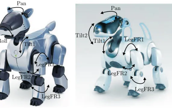
Although the number of joints stayed the same, some of them changed in function or position. Not all of the robots joints are relevant for robot soccer. (e.g. the newly de- signed tail joints are not used for game play in RoboCup) but some changes were more important. The biggest changes that have an impact on RoboCup concerns are the head joints. Like in the ERS-210, there are three joints for the head motion. On the ERS-210 these were: one pan joint (located inside the head), one roll joint (also located inside the head) and one tilt joint (located inside the robot´s body core). On the ERS-7 the roll joint was replaced by a second tilt joint (located inside the head). Also the position of the pan joint was changed (from inside the head (ERS-210) to inside the robot body core (ERS-7)).
their equivalent in the ERS-210. Sony did not provide any specification sheets for that but our tests have shown it.
Apart from the joints the button interface was changed, too. The ERS-210 had two buttons on the head and one button on the back. All of them were physical buttons which means that they had to be pressed.
The ERS-7 has four buttons: one on the head and three on the back; all of them are electro-statical buttons which means they only have to be touched.
Sony also did some work on the robot’s computer core. The ERS-7 has 64 megabyte of physical memory which is twice the amount of RAM compared to the ERS-210A. The processing power was also improved for the ERS-7, it now has a 576 MHz CPU compared to the 384 MHz CPU of the ERS-210A. The W-LAN(802.11b) which was optional on the ERS-210 is now built-in.
According to the technical specifications the camera was improved on the ERS-7. The resolution of the old camera was 176 x 144 pixels on the UV channels (color information) and 352 x 288 on the Y channel (brightness information). The resolution of the new camera is 208 x 160 on the UV channels and 416 x 320 on the Y channel. Unfortunately, this improvement is only of limited advantage, as the camera also introduced previously unheard of problems like lens distortion and insufficient color correctness, which in the end renders the new camera’s images worse than those of the old camera.
3.2 New SDK
Since the introduction of the ERS-7 into the team it showed problems in frequent shut- downs. One of the main causes was ”jamming” which means a malfunction in the joints of the robot. This occurs when the robot tries to address a joint angle which cannot be obtained physically. The ERS-7 has a built-in protection to prevent the robot damaging itself. This protection is called JamDetection. The new SDK offers two new methods to control the JamDetection. The first method is the notification of a JamDetectionThresh- old. When the default JamDetectionThreshold value is too strict, the programmer can add the following line to the file VRCOMM.CFG in the folder /OPEN-R/SYSTEM/CONF/:
JamDetectionHighThreshold
But this did not solve the shutdown problems. Another method which unfortunately includes the risk of damaging the robot is to delete the EmergencyMonitor from the code for the robot. The EmergencyMonitor controls all processes of the robot and is the protection against the robot damaging itself. It is responsible for any emergency shutdown. Deleting this monitor solves the problem of the shutdowns of jamming, but any other protection against problems like battery overcurrent is also deleted. This method requires careful controlling of the robot by its user to prevent the robot from any damage.
3.3 Software changes
The new hardware forced us to change the software in all modules where modified hard- ware like joints or sensors is used. On some solutions this is reflected only in some
parameter tuning or changes, but on others there was more work to do.
3.3.1 Development of a new walking gait
As far as new hardware was concerned, a new walking gait was required. The InvKin- WalkingEngine was used to develop such a gait (see chapter 3.9.1 in the GT2003 Team- report [5]).
Basically a walk consists of several foot positions resulting from a given parameter set of joint angles for each leg. The actual walk is based on a rectangular shape which seperated a movement cycle into 4 phases (see fig. 3.3):
1. ground phase 2. lifting phase 3. air phase 4. lowering phase
Figure 3.3: Step cycle: on the left side one can see how the different phases belong to the step cycle of the robot. On the right side one can see the timing of the cycle.
The aim is to find a parameter set which allows a robot to move fast from one point to another. For the ERS-210 useful parameters have already been found, but used on an ERS-7 they were completely useless.
In order to find appropriate parameters quickly, the (1 + 1) evolution strategy was used.
It belongs to the family of the (µ+λ) evolution strategies. µ is the number of parents from which λ offsprings are generated. So in our case we started with 1 parent, created 1 offspring and then we compared them with a fitness function F. A fitness function is a function which is used to select individuals for mutation and crossover in the next generation.
The evolution strategy we used was also equipped with a self adapting mutation strength, the so called 1/5th-rule, which means that on average 1 of 5 offsprings should be better than its parent. If more offsprings are better, the mutation strength will be risen. Instead if the amount of weaker offsprings increases too much, the mutation strength will be lowered. For further information see [13].
ment progress to the front or to the back, dy the progress sidewards, dθ indicates the degree of movement around the vertical axis of a robot, anddt specifies the time in which each of the three movements should have been done (see fig. 3.4).
Figure 3.4: General movement of a robot
There have been two approaches to develop a new walking gait. In both the robot starts from one goal point and tries to reach the opposite goal point in a specified amount of time. A goal point is defined as the center point of the goal line.
First Approach
In the first approach, the robot corrects his walk direction using its self locator, so the movement was described as [dx, dy, dθ, dt], while dy and dθ depend on the directional correction of the robot (see fig. 3.5(a) on page 18). Due to the fact that the hardware of a robot is not placed absolutely symmetric, the center of gravity is not perfectly in the center of a robot. For this reason a robot will always have to correct its direction during a walk.
In this approach the fitness of a parameter set is mesured by the distance g reached at the end of a walk. So the fitness function of the first approach is:
F =g (3.1)
The predefined time in both approaches is chosen in a way that the robot reaches the opposite penalty area due to the fact that the self locator has an accuracy of about ±10 cm and the friction of the ground might not be constantly the same on the whole field.
So a longer distance leads to minor errors in the measurement.
procedure of the first approach:
The robot:
1. aligns at a goal point looking straight ahead to the opposite goal, 2. walks ahead while localizing and correcting its direction,
3. stops after a predefined amount of time and localizes,
4. measures the reached distance and compares it with the distance reached by the parameter set of the parent generation,
5. moves to the nearest goal point and restarts.
Second approach:
The main idea of the second approach is to achieve a fast walk without any correction of the direction, so the movement is given as [dx,0,0, dt] (see fig. 3.5(b) on the following page). The fitness function F consideres the distance g and, in difference to the first approach, the deviation h to the real straight walk too. So the fitness function of the second approach is
F =g−β∗h (3.2)
where β weights the straightness when calculating the fitness of a parameter set, which allows to define the importance of the deviation during the evolution.
procedure of the second approach:
The robot:
1. aligns at a goal point looking straight ahead to the opposite goal, 2. walks ahead without any correction of the walk direction,
3. stops after a predefined amount of time and localizes,
4. measures the reached distance and compares it with the result of the parent, 5. moves to the nearest goal point and restarts.
In both approaches a parameter set of an offspring, which is better than its parent, is evaluated 2 - 3 times to ensure that it is worthwhile to proceed the evolution with that new parameter. If this is really the case, a new generation starts and the last offspring becomes a parent.
Due to the fact that the first approach allows more than only one robot to walk on the same playing field at the same time, which is not the case in the second approach, where a collision cannot always be prevented without intervention by external control instances like for example a human, the Microsoft Hellhounds mainly focused their evolution on the first approach and achieved a 34 ±1 cm/s walk.
(a) First approach (b) Second approach
Figure 3.5: Different evolution approaches
3.3.2 New kicks and MOFs
Because of the changes to the ERS-7, i.e. its modified physical dimensions (see chapter 3.1 on page 13), the 2003 versions of all movements were rendered ineffective: the kicks and catches which require the ball to be in front of the Aibo failed, while the kicks which need the ball to the side of the Aibo worked, but only barely. These had to be tuned and new moves for the kicks with the ball in front of the Aibo had to be designed.
That is why we created new kicks. Normal kicks are motion files from now on referred to as “MOF” files, due to their .mof file extension. There are other possibilities to kick the ball. For example a head control (see chapter 2 on page 6) mode can be created, which lifts the head up, turns it to a side, then takes the head down and turns it to the other side. If a ball lies in front of the Aibo, it can kick the ball with such a head control mode.
Or the Aibo can simply run against the ball, inducing its momentum onto the ball.
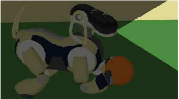
For the GermanOpen 2004 (see chapter 7.1 on page 77), only MOF kicks were used, but motion files can be used in other situations as well. For instance, while we created a number of new kicks, we couldn’t find suitable movements to be able to kick the ball into every direction desired. So, we decided to let the robot approach the ball, then let them turn until they reached an angle to the ball which would allow one of our kicks to move the ball into the desired direction. Initially, we tried to do the turning via our motion engine. Unfortunately though, we quickly realized that this engine was not precise enough without visual input, which could not be provided, since the Aibo´s head in these circumstances was already over the ball and could not see it (see fig. 3.3.2 on the following page). Additionally, this approach would cause serious maintenance work every time we incorporated a new set of walking parameters. So, we approached this problem with mofs as well. We designed mof parameters which would turn the robot around a fixed point by 30, 60, 90, 120 and 180 degrees, respectively. This seemed to work well in our test games
Figure 3.6: An Aibo which turns around a ball and cannot see it. To illustrate this the opening angle of the camera is lit.
against the ERS-210 robots. Either, the new robots were fast enough to have the turn completed, before any interfering ERS-210 would arrive and even if the ERS-7 didn’t have the time, it would have enough power to push the smaller ERS-210 out of the way and complete its turn. However, in the first games against other ERS-7 robots, this didn’t work as the ERS-7s wouldn’t be pushed away and the kick failed. So, we eventually decided against the strategy of turning around the ball via mof special actions.
We also used motion files for cheering (see chapter 8 on page 85).
MOF file description
Short patterns of motion are written in files. Such files are called mof (motion file) and have the extension “.mof”. One such example can be seen in figure 3.3.2 on the following page. In the first line of the file, a name must be specified via the motion id keyword.
Every normal kick has one label called start, these labels are used as entry points. More than one label can be defined to create several entry points. The default entry point of a mof is specified in the file “extern.mof”. The last line of a mof contains the return instruction: “transition allMotions extern start”. Between the entry point and the return instruction there are so-called “motion vectors”. There are two kinds of vectors, joint and pid vectors. Via the pid vectors pid values of a servo gain are set (see capter 2 on page 6 or fig. 3.8 on the following page). The line starts with “pid”, to mark the line as a pid vector. Then the p, i and d values need to be set. This kind of vector is only used in wakeup motions, to switch off and reset the joints (see fig. 3.3.2 on the next page). If a value is irrelevant, it is marked as “don’t care” with “˜”. More important is the joint vector (see fig. 3.9(a) on page 21), which is used in nearly every kick. It is a sequence of 20 values, 18 joint, 1 status, 1 time (for don’t care the “˜” is used, too). Time means the delay time until the next vector can start. The status value determines whether the joint movement is interpolated over the time value (value = 1) or as fast as the joint servos allow (value = 0). The first three values of the joints represent the head joint values, the first is the headTilt1, the second the headPan and the third the headTilt2. The next
Label Return instraction Joint vector PID vector
comment Don`t care
Kick ID (Name of the Kick)
Head value
Mouth and Tail value
Fore right leg Status (interpolate)
Time to execute
Figure 3.7: “wakeUp” mof as example for a motion file
Pan
Tilt1
LegFR1 LegFR2
LegFR3 Roll
(a) Overview of the joints of a ERS-210
Pan
Tilt1 Tilt2
LegFR1
LegFR2
LegFR3
(b) Overview of the joints of a ERS-7
Figure 3.8: overview of the joints of ERS-210 and ERS-7. The roll joint of the ERS-210 has changed to a tilt2 joint of the ERS-7
headTilt headPan neckTilt mouth tailPan tailTilt legFR1 legFR2 legFR3 legFL1 legFL2 legFL3 legHR1 legHR2 legHR3 legHL1 legHL2 legHL3 status time
} } } } }
Haed
Left Right
Left Right
Fore
Hind
} }
(a) the format of the joint data vector
"pid"
name p value i value d value
Mark
Joint name (headPan, legFR1)
}PID value
(b) the format of the pid data vector
Figure 3.9: overview of the type of data vectors of a mof file.
(a) Overview of Mof Tester Dialog with BashPrecize as example for a motion
Motin Selector
Special Action Selector
(b) Overview of the MotionTester dialog
Figure 3.10: mof and motion tester dialog
value is for the mouth and the next two are for the tail. Then four triplets follow, one triplet for each leg, the first leg is the front left one, the next is front right, then behind left and behind right. The values of the triplets are for the joints from core to paw (see fig. 3.3.2 on the previous page). To make a motion file more readable, comments may be inserted, which will start with two “\”.
Tools
RoboControl has two dialogs, used to create new motion files, called “MOF tester” and
“Motion tester” [5]. The “MOF tester” dialog (see fig. 3.10(a)) has an edit box and 6 buttons:
• Read
• Execute
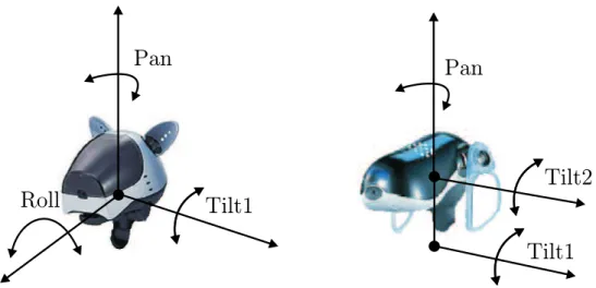
Pan
Roll
Pan
Tilt1
Tilt2
Tilt1
Figure 3.11: 3 headjoint values pan tilt and roll. The roll joint of the ERS-210 had changed to tilt2 in the ERS-7
• Execute in SlowMotion
• Stop
• Convert
• Mirror
The “Read” button reads the current joint values of the connected and inserts the joint vector into the edit box, the “Execute” button sends a motion request with the selected joint vectors from the edit box to the robot, and the button called “Execute in SlowMo- tion” multiplies a delay value from the editbox right next to the button to the motion request before it send it. The “stop” button immediately stops the Aibo’s motion, the
“convert” button converts the motion into raw data which is a format that can be placed in the source code and the “mirror” button switches the right side joint values to the left and vice versa, this can be used to mirror a kick to the left easily to get a exactly same kick to the right. At the beginning of the project group, there was a conflict with the head joint values. Due to the ERS-7 head only having the pan joint moving sidewards (as opposed to the ERS-210 head having two, the pan and the roll) (see fig. 3.3.2) updates to the “MOF tester” had to be made, adapting to this new joint layout.
Using the “MOF tester” requires the use of a bug workaround. Since in theDebug solution of the motion control module a bug occurs, that won’t allow to reset the joint gains, the Aibo needs to be booted with the Default solution and then switched to Debug. This ensures the Aibo performs its “getup move”, which automatically resets the gains, before switching to debug mode.
This bug has not yet been fixed since it is deeply rooted in the framework. Since for testing MOFs there needs to be a connection established with robotcontrol anyway, this does not cause much overhead complications.
With the “Motion tester” dialog (See fig. 3.10(b) on the preceding page), motion files can be executed. Here they are called special actions. The ”Motion tester” has a combo box, a send and a reset button. In the combobox, the motion type will be selected for special actions such as specialAction and a new combobox will appear, with all available special actions. The selected specialAction will be executed in a loop from a send command until the reset button is triggered.
To execute a motion with the motion tester, it must be registered in the code as a special acion, the default solution has to be selected in the motion control module and the behavior must be disabled (as it would overwrite any motion request otherwise). To register a motion, the joint vectors must be saved in a file in the mof directory, the MotionRequest.h and the extern.mof must be updated.
Tuning a mof
There are several ways to tune a movement, it can be made faster, stronger or more precise. It is difficult to tune a movement though, one problem is that often a faster kick is softer or less accurate. On the other hand an opponent can disturb a slow shot more easily. It might place itself in the shot path or push against the robot, thus interfering with and possibly destroying the entire motion sequence.
The “MOF tester” cannot be used to tune a kick, because if the DebugMotion is running, the engines are weaker and slower, therefore, for each change it is necesary to compile and create a new memory stick. This would take a lot of time, however, this can be improved with a small trick: To test modified versions of one motion, files from other motions can be used. So more than one change can be tested with one compilation. The “overwritten”
motions should be carefully backed up though, so they can be restored, once the modified mof is finished.
Before movement tuning can start, the movement in question must be thoroughly analysed, tested in several scenarios and setups and all observations should be noted meticulously.
Often a change makes the motions better at some scenario while it weakens the motion in another. We selected scenarios which are important in games and defined what makes a result acceptable. Then we subsequently left out different vector lines of the motion to find out which steps were important for the result and which could be left out. Usually we changed only one joint vector at a time, because it is easier to find the right value that way. Often when we tried to change several joint values, we encountered problems to identify the “correct wrong” value.
For example we have created a new backward kick called “MSH7NewBicycle” which is composed of three actions: 1) the catches the ball, 2) it lifts it up onto its neck, and 3) it sits up and the ball rolls down the back. One problem was that the kick would take more than 3 seconds to execute, which would break a rule called ball-holding (Rules see section Rules 2.1 on page 6). So the kick was in a first phase tuned that it took less than 3 seconds, but by doing so it became inexact: the ball would roll backward but strew. We considered this as acceptable though, because we created the kick to get the ball away from the border and the kick accomplished that. A second problem though was that if an opponent knocked against our robot, it would lose the ball. This can become a problem, because if this happens near the own goal, the ball might incidentally roll into it; this in fact occured during the AmericanOpen (see 7.3.2 on page 83). We have tried many changes but none has solved this problem. Eventually, we found out, that the Aibo only lost the ball when the opponent knocked from the side where the Aibo wanted to lift up the ball from. That is why we decided to create two kicks, one that lifts the ball over the left side and one over the right side. Despite all these efforts the kick didn’t stand the test of time as the decision of which of the two versions to chose depended on a working opponent robot detection. Unfortunately, this opponent detection could not be provided to date, so we had to dismiss this kick as we did not want to risk scoring own goals.
(see 4.3.8 on page 44)
All the MOFs we created fall into four categories:
1. Kicks that were used during the games 2. Turn movements
3. Cheering/Audience amusement 4. MOFs that were discarded
The first category includes all those MOFs that were in fact used during the games to kick the ball in some direction. The second category includes all turning moves that are used to cover situations, where the robot is positioned inappropriately towards the ball for any of our kicks. These movements align the robot to enable it to use one of the normal kicks.
The third category includes all MOFs, that are not suited for ingame use, but are in one way or the other visually impressive, stunning or just too entertaining to be kept from the public. The fourth category includes all those MOFs that ultimately were not used at all, because they didn’t work at all, were inferior to other moves of equal kind or rejected because of no use for the behavior because the situations the kick would be useful do not occur frequently enough or require a degree of self-localization which simply cannot be provided by current means.
MOFs we used in the games
The kicks MSH7NewBicycleFromLeft (fig. 3.12), MSH7unswBash (fig. 3.13), MSH7SlapLeft (fig. 3.14 on the following page) and MSH7LeftHook (fig. 3.15 on the next page) actually were used for the games.
(a) catch ball (b) put ball to right (c) put ball in neck (d) sit and stay up
Figure 3.12: MSH7NewBicycleFromRight
(a) ready (b) catch ball (c) lift arms (d) hit ball
Figure 3.13: The MSH7unswBash was taken from last year´s code and adapted to the new robot.
(a) ready (b) lift arm (c) hit ball (d) finished
Figure 3.14: The MSH7SlapLeft was created to quickly move the ball from the border by hitting it from above with the left arm.
(a) ready (b) get behind ball (side view)
(c) get behind ball (front view)
(d) hit ball
Figure 3.15: The MSH7LeftHook is a strong forward kick.
Turning MOFs
We created MOFs to turn around the ball for 30,60,90,120,180 degrees to the left or right and called them “MSH7Turn + direction + angle” (for instance MSH7Left90), because for a few angles, especially for angles over 90 degrees we did not find any suitable kicks. For the turning motions the ball must lie in front of the Aibo, then the Aibo lifts up and holds it with its front legs, so that the opponent cannot reach the ball, and then turns for the specified angle. We used this for testing only, due to reasons specified above see 3.3.2 on page 18, and replaced them later by a special walking engine InvKin:MSH2004TurnWithBall (see 3.3.1 on page 15).
MOFs for cheering/audience amusement
We created some kicks, which are nice to watch, but really aren’t of any use for a game, because they are too slow or weak or do not even work the way we intended them to. So we did not use them except for cheering/show-off reasons. Such kicks include the like of MSH7FakeKickRight/Left, MSH7ComplicatedKick and MSH7StrangeBackSlow. Except for these kicks, which were downgraded, we also created motion files for cheering, e.g. for the DemoStick, Chapter 8 on page 85, that were never meant to be used in game, but explicitly created for audience display.
• MSH7FakeKickRight
The MSH7FakeKickRight catches the ball, then hits it with the left paw to roll it to the right paw. Then the right paw hits the ball and only then the ball rolls forward.
Slow and unusable for a game, but visually impressive.
• MSH7ComplicatedKick
If the Aibo executes the MSH7ComplicatedKick it will only move one single joint each motion step. This takes a lot of time, but it is nice to watch, because the motion looks like“robot stop motion”, again this was used for audience amusement only since it was no good for a game.
• MSH7VanGogh
This motion was initially not meant for cheering. As the ears seriously hindered some of our kicks (especially the MSH7NewBicycle kicks), we wanted to get rid of the ears. Unfortunately, at game start the robots needed their ears put in place by official ruling (see 2.1 on page 6). So, our only chance of using those kicks was to let the robot remove their ears themselves. Since this action took quite some time (even though it was perfectly legal), officials later allowed all teams to start a game with their ears off, so our vanGogh move later was degraded to cheering/amusement status.
Rejected MOFs
We rejected some of our MOFs for different reasons like the kick not seeming desirable in any scenario. Such a kick is the MSH710cm, which reliably moves the ball forward for 10 centimeters, which is of no use since in that case it should rather be dribbled forward.
In other cases the kick did not work at all like the MSH7ABombBehind (the Aibo often moved the ball in many different unpredictable directions). Some kicks were superceded by other, more efficient MOFs like the MSH7ForwardLeft for example.
Chapter 4
Image Processing
The ImageProcessor module is analyzing the image sensor data of the robot. Mainly objects allowed on the playing field are recognized by the image processor [see Rulebook].
So the image processor is the only module that provides input data about the vision of a robot while playing soccer. The legacy image processor from the GermanTeam-Release 2003 is the GT2003ImageProcessor [5].
4.1 Motivation
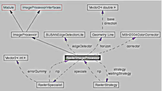
One of the first tasks of the projectgroup to acquaint itself with the GT-Code was to make several specialists of the GT2003ImageProcessor more scalable. For example the Ball Specialist of the GT2003ImageProcessor used a fixed number of points at the edge of a given orange ball in a frame, which were taken into account to calculate the circle which fits best the seen ball. It was regarded as a good enhancement to dynamically set this value higher or lower depending on free processing time. Nevertheless it was just a hack to enhance the scalability of an existing solution. In order to that it was no surprise that soon the idea was born to implement a new, clean Image Processor from scratch, which would overcome the limitations of the existing ones. A modular concept was demanded, which divided the tasks of the Image Processor in Ball, Goal, Landmark, Field and Opponent detection. In this context the main idea was to give dynamically priority to those tasks, which are most important in a given situation. In order to make this possible the Image Processor would have to have control over each specialist. To guarantee even more scalability the rastersize (i. e. the amount of lines/ rows considered in calculations) and therefore processing time should be adjustable too, not only global for all specialists but individually changeable for each of them. All in all the new Image Processor should be able to dynamically switch between optimal results in a reasonable processing time at the one end, and fast approximative solutions at the cost of accuracy of the detected objects at the other end. With this concept in mind work on the Raster Image Processor (RIP) started.
At the beginning of the project we analyzed the preconditions of our plans to implement a virtual robot playing soccer. We were dissapointed about the self-, ball- and opponent localization. We found out that the most of the accuracy isn’t lost in the locator so- lutions of the German Team Release, but in the image processing solution. Therefor it was our aim to increase the accuracy of the detection algorithms while decreasing their misconceiving. Since one of our main intentions was to implement resource sharing for
27
The GT2003ImageProcessor did not support this feature and the most of its detection algorithms weren’t scalable.
4.1.1 Color Correction
The image provided by the ERS-7 robot isn’t provided equally over all the area of the image. Especially in the corners of the image it is too blue and a little bit dark. So we needed a pixel based color correction. This wasn’t done by the PG, but by a faculty staff member. He implemented a look up table with correction values for each pixel of the image. With this table every pixel on the image can be corrected. The correction can be individually adapted to every single ERS-7 robot. This is done by some color coefficients as input data for the look up table creation, which are calculated from some test images taken out of several robots. Our intention was to use this color correction directly in the scan process, without correcting the whole image. Since we wanted to use the ColorTableTSL, we had to integrate the color correction in ColorTableTSL-Calibration-Tool. Otherwise the color classification is defective if the robot uses the color correction.
(a) Original image (b) Corrected image
Figure 4.1: Image as seen by an ERS-7 on the playing field
4.1.2 Supporting Color Tables
The ColorTable module represents the classification of several color classes of interest.
That means a disjoint definition of semantic colors like black, orange or pink in the colorspace. An example for such a classification is shown in 4.2(b) on the following page.
The GT2003ImageProcessor was implemented for use with ColorTable64 and doesn’t support any other ColorTable-module. Since the GermanTeam has more than one imple- mentation of the ColorTable module, we wanted to have a image processor that supports the ColorTable module in general. The two additional solutions for the ColorTable module we wanted to use are the ColorTableTSL[8] and ColorTable32K.
4.2 EdgeDetection
To efficiently detect the shape of objects in an image, we firstly need some feature points of these shapes. We call themedge points. Almost every detection algorithm ,we considered
(a) Original image (b) Image classified by ColorTable32K
Figure 4.2: Image as seen by an ERS-7 robot on the playing field.
to implement, needs some pixels of the object’s outline. So we wanted to be able to detect these feature points.
We define edge points as pixels that have a large difference of brightness and color com- pared to their neighbours. To detect such points we wanted to use a simple kind of spatial filter, that generates an amount of edginess for a pixel. After a few tests with different filters we decided to use some simple first derivative gradient filters [9] shown in figure 4.2.
The image is provided in the YUV colorspace. We use all 3 dimensions to calculate the edginess of one pixel. Let’s see how the horizontal edginess eh, vertical edginess ev and the cross edginess ec are calculated:
eh =|h1y −h2y|+|h1u −h2u|+|h1v−h2v| (4.1) ev =|v1y −v2y|+|v1u−v2u|+|v1v−v2v| (4.2) ec =neehv, otherwise, if eh>ev (4.3) Note, thatec is usually calculated withe2c =horizontalgradient2+verticalgradient2 and the direction of the edge can be calculated with arctan(vertical gradient/horizontal gradient).
With arctan(eh/ev) we can only differ between horizontal, vertical and square lines.
(a) horizontal gradient filter (b) vertical gradient filter (c) cross gradient filter
Figure 4.3: Basic gradient filters - Note, that p is the considered pixel. The green pixels represent the neighbourhood used to calculate the edginess.
We combined these filters with a Bresenham line scan [2], the idea of non-maxima- suppression and threshold hysteresis as used in Canny Edge Detectors [6]. This led to a kind of edge scanner that iterates from pixel to pixel in a given direction, while searching