IO3
Modul Optics
Diffraction
The phenomenon of diffraction is an essential manifestation of the wave properties of light. As a part of geometrical optics, this phenomenon can not be understood because the light propagates in three dimensional space, which in a straight line propagation is blocked by an obstacle.
Diffraction is of great importance in the scientific, as well as in the tech- nical sense. In this experiment, the phenomenon using the diffraction slit and lattice will be investigated.
The phenomenon of diffraction is an essential manifestation of the wave properties of light. As a part of geometrical optics, this phenomenon can not be understood because the light propagates in three dimensional space, which in a straight line propagation is blocked by an obstacle. Diffrac- tion is of great importance in the scientific, as well as in the technical sense. In this experiment, the phenomenon using the diffraction slit and lattice will be investigated.
c
AP, Departement Physik, Universität Basel, August 2018
1.1 Preliminary Questions
• Which phenomena do you know where the wave properties of light are seen?
• Which phenomena do you know where the particle properties of light are seen?
• What does the Huygen’s principle?
• Through which quantities are (light)-waves completely defined?
• What is meant by the term coherence? What is the difference between temporal and spatial coherence?
• In what wavelength range is the observable optical spectrum?
• What is the relationship between wavelength and frequency in the case of electromag- netic radiation?
• What is meant by the term intensity and which physical unit does it have?
• How are the Bessel functions of the first kind defined? Which differential equation is used by these functions and where does it occur on, or trough which symmetry does it occur?
• What is meant by the terms constructive and destructive interference?
• Interference is a direct consequence of the superposition principle of waves. Why apply this superposition principle? (Note: it is a mathematical statement retrieved from linear equations).
• Deduce the condition for constructive interference from the double slit.
1.2 Theory
1.2.1 The Wave properties of Light
The nature of light has long been controversial because it both gives phenomena, which can only be explained by accepting a stream of particles and phenomena such as it should only be viewed by the adoption of light waves. Ultimately, this contradiction was achieved by the wave-particle-duality of quantum mechanics.
The observed diffraction pattern in this experiment and their intensity distribution can only be understood if the light has certain characteristics of a wave as it propagates in space re- gions, which are not directly accessible in straight lined propagation. This behavior can be explained relatively clearly, using the HUYGEN’SPRINCIPLE1which states:
Each point of a wavefront can be considered as the starting point of a so-called elementary wave.
Through superposition of all elementary waves, one obtains the resulting wavefront.
This principle allows to understand and construct both the phenomenon of diffraction and the refraction, respectively, like the corresponding phenomenon that comes about (see Figure
1Christiaan Huygens, 1629-1695
1.1).
Mathematically, light waves described as follows:
ψ(~r,t,ω) = A·ei(~k~r−ωt+Φ) (1.1) This is the general form of aPLANE WAVE, which represents the solution to the HOMOGE- NEOUS WAVE EQUATION. In this equation, it is a homogeneous, linear differential equa- tion of the 2nd order. From mathematics, it is known that any linear combination of solutions of a linear equation, in turn represent a solution of the same equation. Consequently, linear combinations of plane waves are still a valid solution to this equation. From this mathematical property, results the SUPERPOSITION PRINCIPLE for waves.
In the following, we restrict ourselves to the one-dimensional case, and a plane wave can then also be represented as follows:
ψ(x,t) = A·sin(ωt−kxx+Φ), (1.2) whereAis the amplitude,ωis the angular frequency,kxis the x-component of the wave vector
~k, andΦis the phase of the wave. It follows that angular frequency and wave vectors are in relation to each other:
ω
c =|~k|= 2π
λ , (1.3)
wherecis theSPEED OF LIGHT andλis theWAVELENGTH of light.
1.2.2 The Significance of the Phase
First, the PHASEseems to be a redundant size here, because of the periodicity of the sine func- tion. However, the phase is of great importance when different waves are related to each other.
Considering two waves of the same form as in Eq. 1.2, we can superimpose them according to the principle of superposition.
However, if both waves are of different phases, the superposition changes the amplitude of the resulting waves. This phenomenon is known as INTERFERENCE. In our example, if we add the amplitudes of the two waves under consideration and it is completely zero, it is called DESTRUCTIVE INTERFERENCE, this is the case when they vibrate in opposite phase of the two shifts, Φ = (2n+1)π ,n ∈ N0. However, if they add to double amplitude, then we speak of CONSTRUCTIVE INTERFERENCE, both waves resonate together in phase, Φ=2nπ,n∈N0.
If the phase of the two waves is not constant, but varies, the result is one temporal sequence of constructive and destructive interference, as for all intermediate stages. Thus, the resulting interference pattern is not constant over time. The examined waves exhibit a temporally con- stant phase relationship, it is said that the waves or the light is COHERENT. In this case, one obtains a stationary interference pattern.
To complete the picture at this point, it should be noted that in addition one distinguishes between TEMPORAL CONSISTENCY and SPATIAL CONSISTENCY. Should a wave be coherent to a time-shifted copy, temporal coherence is necessary. The temporal coherence of light by its spectral composition is necessary. Monochromatic light, e.g. as it is emitted from a laser, is always full time coherent. Whereas light consisting from more wavelengths, such as sunlight, is generally incoherent.
Coherence is required when the light has a spatially shifted copy to interfere with itself. This is exactly what is considered in the current experiment. Spatial coherence depends, in many
4
cases, from the shape and extent of the given light source. It should be noted at this point, that only a laser light as used in this experiment, emits with the greatest spatial coherence ever.
You can be here up to several hundred meters.
1.2.3 The Concept of Intensity
The concept of INTENSITY is already known by most students at the beginning of the course.
Nevertheless, many find it difficult to explain this concept clearly, and it is intuitive to gain understanding. However, in physics, there is a precise and logical definition of this physical size:
Intensity = Energy
Area·time ;[Intensity] = J
s·m2 = W
m2. (1.4)
In other words, it is concerned with the intensity to a power density based on a certain area.
It is also described by a surface power density. Based on the above definition, it is apparent that this size is also related to the energy of a wave. For waves, it is generally that:
I ∝A2, (1.5)
where Ais the amplitude of the corresponding wave. Furthermore, it is important that, e.g.
for a point source, a commonly used physics model idea is that the intensity falls as 1/r2. If, for example, the total radiated powerPof a point source is known, then it can be shown that the intensity at a distance r is:
I(r) = P
4πr2 (1.6)
results. Mind you, this is all just in a vacuum, in the absence of an absorbent medium, respec- tively. Is also an absorbing medium present, so it can be shown that the intensity decreases exponentially:
I(r) = I0·e−µr. (1.7)
This regularity is named BEER-LAMBERTIAN LAW and designated byµ, the so-called AB- SORPTION COEFFICIENT. This is a property of material, which may even depend on the wavelength of the radiation. can.
1.2.4 Diffraction at a Slit
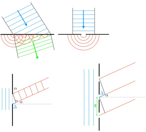
Now consider the case where a front smooth wave is running on a slit. If this slit is large com- pared to the wavelength of the light, the wave properties are not observable. Consequently, the slit must be in the order of magnitude of the wavelength of the light used. Now consider Figure 1.1. There, it is seen that the wave trains, which have been diffracted at the same angle with respect to the optical axis, a path difference of∆is exhibited. So some wave trains need to travel a greater distance than others.
From the above discussion, the importance of the phase should be apparent now, as the con- dition for constructive or destructive interference can be derived. In Figure 1.1, the two outer wave trains are only shown that two of the border points of the slit can be bent. However, be- tween these, one can arbitrarily imagine many other wave trains. If between these two outer wave trains, a retardation of nλ occurs, there is obviously between the first (that is, one of the external) and the middle wave train, a retardation ofnλ/2, so they interfere destructive.
Similarly, destructive interference occurs between the second and the next higher wave train, etc .. Thus, a minimum of intensity occurs. Inscribed is the angle at which the diffracted wave
g
Figure 1.1: HUYGENS PRINCIPLE and diffraction at a slit or the grid. These sketches are a mandatory tool to derive the condition for maxima / minima of intensity.
can be observed byα, and the width of the slit withb, then by means of a sketch as those in Figure 1.1 below condition for a minimum of intensity derived at the slit:
∆=2nπ =n·λ= b·sinα sinα= nλ
b , n∈N (1.8)
The calculation of the intensity distribution, which is observed in the experiment, is relatively complicated and should not presented at this point. 2 For the normalized intensity, the inten- sity of the main maximum is true:
I IH =
sin2U U2
, U:= k·bsinα
2 (1.9)
2The total equation can be researched in the references at the end of this manual, and it is usually treated in physics 4.
6
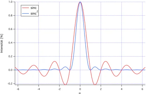
The progression of the intensity is given by the quadrant, as aCARDINAL SINE FUNCTIONor sinc function. Figure 1.2 shows an example of this function. The maximum in the middle of the display area is referred to as the main peak and exceeding all other maxima, the so-called secondary maxima, by far.
1.0
0.8
0.6
0.4
0.2
0.0
-0.2
Intensitt [%]
-6 -4 -2 0 2 4 6
α sinc
sinc2
Figure 1.2: This graph shows the course of theCARDINAL SINE FUNCTION, normalized to the intensity of the main maximum. Consequently, the main maximum has reached 1, while the so-called side lobes have a significantly lower intensity.
The sinc function is identical to the SPHERICAL BESSEL FUNCTION FIRST ART and as such, a solution of BESSEL’SDIFFERENTIAL EQUATION, which the waves of physics, as well as for many other radially symmetric problems, of enormous importance.
1.2.5 Diffraction Grating
In addition to the diffraction at a slit, in this experiment, the diffraction grating is also ob- served. The diffraction grating is a generalization of the diffraction at a double slit, which is an experiment with extreme importance in physics because of the transition from classical physics to quantum mechanics can be observed. Furthermore, having the diffraction grating also has some technical meaning, as it is the main component of a grating spectrometer.
Again, we look at Figure 1.1 and consult the section on the phase of the experiment. Again, it is important to analyze the circumstances under which constructive or destructive interfer- ence can take place. Now, we consider wave trains, which, in turn, under the same diffraction angleαwith respect to the optical axis, are to be observed. However, these wave trains now pass different columns of the grating. The grating is now essentially characterized by the lat- tice constantg. Again, it turns out on the basis of the sketch that different waves trains have a retardation from one another. To ensure that all wave trains, which at the same diffraction angle are observed, but different columns, constructively interfere, they must have a retar- dation of nλ . Taking advantage of the definition of the Sinus with respect to the opposite side and the hypotenuse of a right triangle, it is obtained for the path difference but also the relationship:
∆=g·sinα,
and finally, the following condition for the maxima of the diffraction grating results in:
sinα= nλ
g , n∈N (1.10)
This formula is of a very similar shape, which for the minima of the diffraction has been derived at the grating, but in this case describes the maxima of the diffraction!
It is emphasized that the diffraction angle αis a function of the wavelength, and thus light of different wavelengths is diffracted differently! Red light has a larger wavelength than blue light, so it is bent more than blue light according to this formula.
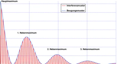
Hauptmaximum
1. Nebenmaximum
2. Nebenmaximum 3. Nebenmaximum Interferenzmuster
Beugungsmuster
Figure 1.3: This graph shows the variation of intensity in the case of diffraction at the grating.
As discussed in the text, here one can recognize it is a superposition of a diffraction pattern and an interference pattern.
Thus, light behaves in the diffraction/diffraction reversed exactly as in the refraction/refraction, where due to dispersion (index of refraction is a function of the wavelength), blue light is re- fracted more than red light.
On the grid, the resulting intensity profile can be calculated. This calculation should not be presented as in the case of diffraction at slit here, instead we look at the result. The following applies:
I IH
= sin
2U U2 ·sin
2W
W2 ,U= πb
λ sinα ,W = πng
λ sinα (1.11)
The first term is identical to the profile of the intensity at a single slit. The second term includes the critical difference. It becomes designated as a (multi beam) interference term. The resulting experiment is the subject of Figure 1.3:
1.3 Experiment
In this experiment, the diffraction grating at a slit is examined. The experiment will be avail- able in the disassembled state and the students are to build the optical apparatus and adjust
8
according to these instructions. The precise adjustment of an optical apparatus may be a time consuming process, so it is done with patience, diligence, and skill!
The correct adjustment of the equipment is to be demonstrated to the assistant before starting with the actual measurements.
The laser and the lenses, which are used in this experiment, are used with caution and the necessary sense of responsibility to handle them.
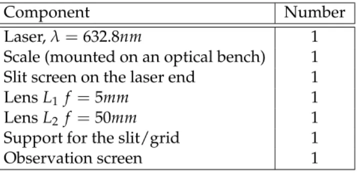
1.3.1 Equipment
Component Number
Laser,λ=632.8nm 1
Scale (mounted on an optical bench) 1 Slit screen on the laser end 1
LensL1 f =5mm 1
LensL2 f =50mm 1
Support for the slit/grid 1
Observation screen 1
1.3.2 Experimental Setup and Adjustment The experimental setup can be found in Figure 1.4:
Figure 1.4: Schematic of the experimental setup: lensesL1,L2, holderH, screenS, laser, and optical bench.
For correct adjustment of the experimental setup, one should proceed as follows:
• Attach the He-Ne laser to the optical bench.
• Screen Sshould be about 1.90 m from the laser and align the laser towards the screen and turn it on.
• HolderHwith e.g. the triple slit is about 50 cm away from the laser on the optical bench.
Direct the laser so that the center of the slit is hit.
• Spherical lensL1up to about 1 cm from the laser (this lens is used to expand laser beam).
The laser must illuminate the slit.
• Remove holderH.
• Lens L2should be mounted about 55 mm in distance from the spherical lens (the con- verging lens serves that parallel to the optical bench to the spherical lens expanded light to lead).
• The collecting lens should now move some towards the spherical lens until the diameter of the laser on the screen expands to approximately 6 mm. (This should give a possible circular profile).
• Check if the beam diameter between the lens and screen is constant, for example, with the help of a sheet of paper.
• HolderHshould be mounted at a distance of approximately 1.50 m on the bench from the screen.
• Optionally, lensL2could be slightly readjusted until the diffraction image is sharp.
1.3.3 Measurements
• Measure all three available slits A (b=0, 12mm), B (b=0, 24mm), and C (b=0, 48mm) individually. Observe and sketch the respective diffraction pattern and write down your observations.
• Use slit B and fix paper on the screen. Mark out the locations of the occurring minima of intensity.
• Diffraction at a post: use the base instead of the slit and observe the diffraction pattern.
Write down and sketch your observations and compare the diffraction image with the three previously observed slits.
• Diffraction at the aperture: insert pinhole, successively at the holes A (b = 0, 12mm), B (b= 0, 24mm) and C (b= 0, 48mm). Record and sketch your observations and diffrac- tion patterns. Use hole B again, and with a paper mounted on the screen, find the max- ima of the intensity on the paper. Determine the diameter of the dark circles.
• Diffraction gratings: use cycles through the three available slits: A (20 slit per cm), B (40 slit per cm), and C (80 slit per cm). Record and sketch your observations of the resulting diffraction images.
• Set again slit C and fix a piece of paper on the observation screen. Transfer the observed diffraction image and the positions of the resulting maxima to the paper. Repeat the measurement for the slits A and B.
• Diffraction on a two-dimensional lattice: there are two different cross lattices available.
Use a sheet of paper to transfer the positions of the observed maxima.
10
1.3.4 Tasks for Evaluation
For the evaluation of the experiments with respect to the diffraction on the slit, the following tasks are met:
• Derive the condition analogous to Equation 1.8, for the maxima of the intensity for a single slit.
• The distance between the slit/grating and observation screen is called L. Derive a rela- tionship between the diffraction anglesα andL, using the definition from the tangent and small-angle approximation. Use this result to derive a relationship between the distancesxnof the minima of the optical axis and the wavelengthλ.
• Calculate for all measured intensity minima the quotient of xn/n, wherexn is the min- imum distance to the optical axis on the screen and n is the order of the minimum.
This ratio should be constant, therefore, calculate the average and standard deviation of xn/n. Using these values, calculate the width the slit. Make a complete error analysis and compare your value with the theoretical value. Plot your results as a graph, i.e.
xn/nandbas a function of the numberNof measurements carried out, including error bars and the calculated mean value.
• Make a sketch in which the diffraction patterns observed for all three slit are shown.
Describe your observations, in particular how the diffraction patterns change with in- creasing slit width. Are your observations consistent with the theoretical expectations?
Explain your answer.
Evaluation of the diffraction on a post:
• Produce graphs similar to those which you already have made for the diffraction slit, that is, xn/n and g as a function of the number N of measurements taken, including associated error bars and the calculated mean value. Compare the results with the given lattice constants.
For the experiment with respect to the diffraction at the pinhole, the following tasks have to be done:
• Measure the diameterdn of all observed minima of the intensity. Compute for all ob- served minima, the quotientdn/kn, analogous to the diffraction at a slit. Again, compute the mean and standard deviation of these ratios. For the minima of the diffraction at the pinhole, the following equation applies:
dn
2·L =kn· λ
D, (1.12)
wheredis the diameter of the pinhole,Lis the distance to the screen,dnis the diameter of the n-th minimum andk1 = 1, 220,k2 = 2, 232,k3 = 3, 238. (Up to three minima are observed.) Compute the hole diameter D using the wavelengthλ = 633nm. Make a complete error analysis.
Required for the analysis of experiments on diffraction grating:
• Plot a graph in which all three observed diffraction patterns are outlined. Describe your observations, especially the dependency of the diffraction pattern on the lattice constant g. Calculate the respective lattice constant of all three grids.
• Calculate the quotientxn/non the slit analogous to the evaluation of the diffraction and compute the mean and standard deviation.
• Again, using your values, calculate the wavelength of the laser light and perform a com- plete error analysis.
• Qualitatively describe how the diffraction pattern of the two-dimensional lattice differ from the one-dimensional.
• From your data, determine the lattice constants in both spatial directions for the two- dimensional grid.
1.4 Literature
• Demtröder Band 2 - Elektrizität und Optik, 6. Auflage: Abschnitt 10.1- 10.5 (für inter- essierte Studenten sein auch Abschnitt 10.6 bis 10.8 empfohlen)
• E. Hecht -Optik, 3. Auflage: Kapitel 9 und 10
12