Interactive 3D Displays
Shaban Shabani Distributed Systems Seminar
ETH Zurich Switzerland sshabani@student.ethz.ch
ABSTRACT
This seminar report studies the notion of interactive displays and is based on four papers, three out of which are related to interaction with 3D displays. The papers are organized in a way such that every subsequent paper supplements some of the limitations of the previous one. The first paper is a project related to 2D projections with interactive surfaces and it stimulates the necessity for 3D displays. The second paper introduces an improved LCD screen designed to en- able multi-touch interaction with 3D displayed objects and off-screen 3D gestures. The third paper shows how to use depth-cameras for direct in-volume interaction with 3D ob- jects. The drawback of this design is the limited viewpoint.
The last paper overcomes this limitation by implementing a 360 degree viewable interactive display.
ACM Classification: H5.2 [Information interfaces and pre- sentation]: User Interfaces. - Graphical user interfaces. - Interaction styles
General terms: Design, Human Factors
Keywords: Interactive surfaces, depth-cameras, surface com- puting, 3D displays, in-volume interaction, 360 degree view- able displays, optical illusion, parabolic mirrors.
INTRODUCTION
With the latest advances in technology, displays have evolved and they are not static anymore. Moreover, they are not used for presenting information only. Nowadays, displays show more dynamic data. Even though the old technique that uses remote controls to interact with displays has several disadvantages, it has seen wide adaption rate and it is still in use. Current displays require more proficient interactivity and touch screens appear to be a reasonable solution. By en- abling direct contact on the screen, touch screens increase the interactivity and allow users to control digital content with great enthusiasm. This technology has been applied in wide range of products including: smartphones, tablets and even bigger displays such as Microsoft Surface, a multi-touch de- vice that allows people to interact with digital contents in the same way as they interact with everyday items. However, the main disadvantage of touch screens is the fact that interac- tions are being limited by the direct physical contact with the screen.
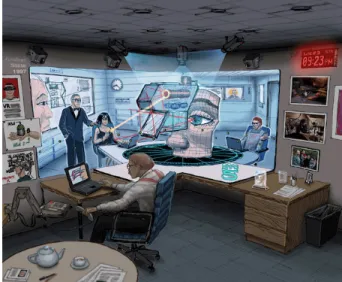
Therefore, in order to have more enhanced interactive dis- plays, the idea is to move the interactivity off the display and make the environment interactive as well. This idea is illustrated in the ”Office of the future” [1], an old concept
dating from 1960’s that has involved a deep of research in this area. The conceptual sketch in Figure 1, demonstrates the possibility of sensing and controlling the whole space of the room by replacing the office lights with projectors and by using synchronized cameras. Thus, images are projected on the surfaces such walls and tables and these surfaces become interactive.
Figure 1: ”Office of the future” sketch
The ”LightSpace” [2] paper is a project developed by Mi- crosoft Research that approaches the concept of the ”Office of the future”.
LIGHTSPACE - the "smart room"
LightSpace is a small room installation which uses multiple depth-cameras and projectors to provide interactive displays.
By making use of augmented reality and surface computing techniques, in LightSpace they provide with what they say spatial computing. The room surfaces such as a standard table and the wall become interactive displays, enabling users to interact with media content on, above and between the displays. Moreover, not only the surfaces are interactive but the space between surfaces is active as well, transforming the whole room into a computer. Projectors and cameras are suspended at a central location above the users, leaving the room space free and configurable (see Figure 2). The user is put inside an interactive environment which is a mixture of the virtual and the real world.
Figure 2: LightSpace room configuration
Design overview
Multiple calibrated depth cameras and projectors are com- bined to allow correct projection of graphics on even moving objects without any user instrumentation.
Depth-cameras such those from PrimeSense1and Canesta2in combination with projectors provide unique capability such that even the smallest corner of the room space is sensed and functions as a display. These can sense the user and the user’s actions, and then the user can choose on which surface the information will be displayed. Cameras and projectors are calibrated to 3D real world coordinates. Initially, cameras capture a 3D mesh model of the entire sensed space in real- time and virtual objects may be placed on top of the mesh in the same scene. With precise projector calibration, these objects are correctly projected in the real space on top of the real objects.
LightSpace emphasizes the following three themes:
Surface everywhere - all physical surfaces inside the room should be interactive displays, e.g. tables, walls.
The room is the computer - not only physical surfaces, but the space between them is active.
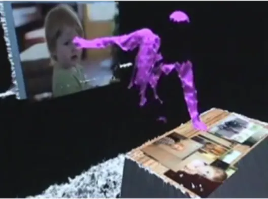
Body as display - the body of the user is transformed into a display as well. Graphics are projected onto the user’s body and this is useful in cases when there is no projection surface available.
Interactions
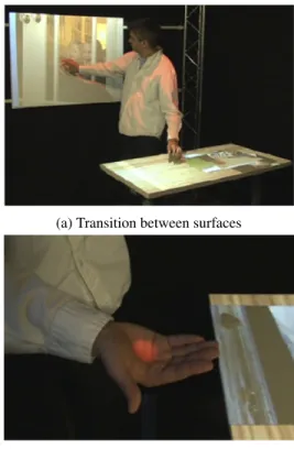
The rich and practical interactions that a user can perform are the strong points of LightSpace. The content projected on a surface can be pictures, videos or documents. Some of the possible interactions are shown in Figure 3. First, the user can use multi-touch on theinteractive surfacesto manipulate with projected content, such as move, resize and rotate the objects (Figure 3a). Second, the user can performtransitions between surfaces, passing an object between displays (Figure 3b). This is simply done by touching first the object and then touching the desired destination surface. In this case, the system detects that both contacts belong to the same user so a connection between surfaces is established. The third and more interesting case is ”picking up” the objects. Users can
1http://www.primesense.com
2http://www.canesta.com
take an object in their hands by dragging it from the table and it is possible to pass it to another user inside the room who can place the object to a different surface, e.g., the wall.
(a) Transition between surfaces
(b) ”Picking up” objects
Figure 3: LightSpace Interactions: a) user performs the tran- sition of an object between surfaces ; b) user holds an object with bare hand
Operation
In order to enable interactions in LightSpace, it is required to detect the presence of a user in the space. Then, the sys- tem needs to detect user touches and manipulations with the projected content. While the depth-cameras track the user’s body and actions, they provide a 3D mesh model of the room in real-time. In order to detect contacts on the surfaces and implement the interaction, LightSpace uses the follow- ing technique: rather than performing calculations directly on the 3D mesh model, data from the 3D mesh model is transformed to an image and then 2D image processing tech- niques are performed (Figure 4). A projection of the 3D data is computed to create a new image that can be thought of as having been generated by a virtual camera. For this purpose, 3 orthographic virtual cameras are used: one giving aplan viewof the room which covers 2m of depth and tracks users in the entire interactive volume, and two other virtual cam- eras configured to capture interactions above the table and wall display surfaces (see Figure 5).
More than surfaces
As LightSpace implements rich set of interactions that can have application in several fields such as education, confer- ence rooms and so on, still the output of the projection is limited to 2D. The need for 3D displays is indisputable. The increasing capacity of computing, the decreasing cost of the
Figure 4: 3D Mesh Model provided by depth-cameras
Figure 5: Three orthographic virtual cameras tracking user’s actions
hardware and the advances in research have brought 3D in many of the things we do. 3D displays offer more Degree of Freedom (DOF) for interaction that can be beneficial for many high-DOF tasks. Additionally, 3D provides more vi- sual information and is more exciting and realistic than 2D.
In order to view and get the feeling of 3D images that are shown in most of 3D displays, in most situations it is re- quired that users wear special glasses. Moreover, most of these displays do not support any interaction from the user’s side. The very few displays that support user interaction, re- quire wearing of additional hardware such as data gloves. In what follows, we describe 3 research projects related to in- teractive 3D displays.
BiDi SCREEN
BiDi screen [3] is the solution that overcomes the mentioned drawbacks of 3D displays and provides 3D interaction with- out requiring users to wear additional hardware. BiDi stands for Bi-Directional because of the fact that light travels in both directions of the screen. There is a screen, and behind it, there are cameras to track what happens in front of the screen. In BiDi researchers have modified LCDs by adding additional layer of sensors to allow both image capture and display. In display mode the screen shows traditional graph- ics and in capture mode the screen captures user actions that happen in front of the screen. This modified LCD screen supports on-screen 2D multi-touch, and more important, it is capable of recognizing 3D hand gestures to control objects on the screen.
Motivation
BiDi implementation is inspired by the next generation of multi-touch devices that rely on optical sensors which are embedded in a LCD matrix typically used for displays. Other technologies which motivate this project are the commercial- ized depth sensitive cameras and the explosion of multi-touch interaction devices. Hence, the idea here is to make use of some of these technologies and integrate their used tech- niques in a single device. The goal is to build a thin portable and mobile display. Moreover, the device should enable touch and 3D gesture interaction with bare hands and still display images without interference. The question is how to capture depth from an LCD display? Several techniques have been considered in capturing depth information of objects in front of the LCD. Initially, the traditional touch technology is considered, where resistive and capacitive touch screens are widely used. These techniques only sense the surface of the screen and cannot sense off-screen gestures. Some capaci- tive solutions detect finger or hands in close distance to the screen but are not able to determine the distance of the hand from the screen.
For implementing the gesture recognition, BiDi screen is di- rectly influenced by the emerging LCDs that use embedded optical sensors to detect multiple points of contact on the screen. For example, Sharp and Planar Systems [4] show LCDs with arrays of optical sensors interlaced within the pixel grid. Touches on the screen are detected by checking the occluded sensors that receive less light. This approach clearly images the objects that are in direct contact with the screen but fail to recognize objects placed in distance from the screen. As the object moves further away, the image be- comes blurred due to the light reflecting off any portion of the object being spread across many sensors.
Design Overview
The key point in BiDi is the modification of the LCD screen.
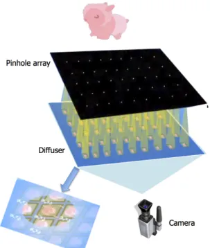
By slightly moving the light-sensing layer from the LCD, the display is used to modulate the light reaching the sensor layer, thereby sense the depth and position of the objects in front of the screen. By simply displaying a pinhole array on the LCD (see Figure 6), hundreds of tiny images are formed on the sensing layer, each of which has a slightly different view of the objects in front of the screen. By analyzing these patterns, it is possible to capture depth information creating 3D images of objects in front of the screen, without requiring direct contact. Due to the lack of development tools for light- sensing LCD displays, diffuser and camera pairs are used instead of an optical sensor layer. The diffuser lies just be- hind the layers and the cameras are positioned 1 meter behind the screen to observe the diffuser. The camera images light cast on the diffuser, which simulates a sensor array. Even though this setup creates thicker device, still it is mobile and portable.
Interactions
BiDi screen supports two main types of interactions. On- screen multi-touch interactions (Figure 7a) enable resizing and rotating the objects by directly touching the screen. More important, off-screen 3D gestures give the chance to move and zoom in/out the objects from distance. By moving the
Figure 6: Design overview of BiDi screen: image capture can be achieved by rearranging the LCD’s components. A pinhole array and a pair of diffuser and camera are used to replace the sensor layer.
hand in front of the screen, the objects can be moved in 4 directions, whereas the distance of the hand from the screen dictates the zoom in/out of the 3D objects.
(a) On-screen multi-touch (b) Off-screen interaction
Figure 7: BiDi interactions Enabling in-volume interactions
Although BiDi provides practical 3D interactions through gesture recognition, it does not enable users to directly in- teract with the 3D virtual world. Similarly to this, there are other projects where physical interaction with 3D objects is not possible since the virtual and physical world is separated by a glass [5]. On the other hand, there exist solutions that support in-volume interaction but they require users to wear special head-worn hardware and data gloves in order to di- rectly interact with 3D content [6]. A solution that over- comes these limitations is HoloDesk [7].
HOLODESK
HoloDesk is an interactive situated augmented reality which gives the possibility to interact with 3D virtual objects. It al- lows users to get their hands inside the display and directly
touch 3D graphics without any body-worn hardware. More- over, it supports physically realistic interaction, which means that during interaction with 3D virtual objects, users can use additional physical objects e.g. paper (Figure 10), to manip- ulate with the virtual objects.
(a) Design Components (b) 3D direct Interactions
Figure 8: HoloDesk configuration Design overview
HoloDesk combines an optical see-through display (beam splitter), Kinect camera, Web Camera and LCD (Figure 8).
The interaction volume is of a desktop size, and it can be viewed through the mirror or beam splitter. The mirror re- flects the light coming from the LCD onto the upper side towards the user. This forms a virtual image which the user sees on the interaction volume, below the beam splitter. The user can reach this volume by placing the hands inside the volume, i.e. hands move below the beam splitter. The LCD is positioned away from the user such that it maximizes the viewable area of the virtual image. The RGB web camera is used to track the user’s head in 6 degrees of freedom. It ensures that the user sees virtual graphics correctly which are registered on top of real objects in the interaction space when looking through the beam splitter. The Kinect camera is mounted above the LCD together with a mirror. The mir- ror is used to fold the Kinect’s optics allowing it to sense the full interaction volume.
Operation
In order to guarantee tight spatial coupling between the input of the physical objects and the output of the virtual objects, calibration is needed. The Kinect camera, the head-tracking camera and the virtual image plane are calibrated relative to each other and to a fixed real-world origin. By continuously estimating the 3D position of the user’s head and constantly updating the rendering of the 3D scene, the correct perspec- tive is displayed to the user. Hence, the real-time mesh data from Kinect are critical in real-time rendering of the 3D scene for the user’s current head position with the ability for hands and other objects to correctly shadow and occlude the virtual. In order to enable interaction directly into the vir- tual scene, they model the 3D shape, motion and deformation of physical objects inside the interaction volume. A critical point is the design of the object grasping. Since in the inter- action process the physical objects are directly linked with virtual objects, it is important to accurately model collision and friction forces, which are done by using the data from
the Kinect camera. In order to model these forces, they in- troduce geometry that approximates the shape of the physical object, in this case the hand, using small spherical rigid bod- ies. One main issue that occurs when users interact with vir- tual objects using these rigid bodies is the interpenetration, as shown in Figures 9b and 9c. The rigid particles intersect and enter inside another rigid virtual object that the user is at- tempting to grasp. This leads to unstable simulation results.
This issue is solved by connecting the intersected particles to another Kinematic particle, such that they do not cause interpenetration in the simulation, as shown in Figure 9d.
Figure 9: HoloDesk: Simulating human grasping
Interactions
HoloDesk allows users to perform rich set of interactions and this is due to the ability to spatially couple virtual onto the real, so it allows the real to interact with the virtual in realistic ways. Users can interact with virtual objects with their bare hands. Additionally, interaction with virtual objects can be done using other physical objects such as a paper or a bowl and this is done as these virtual objects were real. The system approximates the shape, the deformation and motion of the objects over time in the interactive volume. For example, the ball sitting on the paper shown in Figure 10, will follow real movements depending on the shape and alignment of the paper as there was a real ball. A similar example is the case with the bowl. Other interactions include juggling with objects or grasping.
One strong side of HoloDesk is that it has many application capabilities. It gives the possibility to rapidly experience a mix of real and virtual content, enabling different gaming ap- plications. An interesting possibility is to sense the ”virtual”
prototype’s shape and size with bare hands. For example, a smartphone that can be stretched to different size, where the virtual object becomes touch-enabled by tracking the user’s hand and actions. Another application is telepresence. The interactions from one user are relayed in real-time to a remote user at another unit and both users share the same virtual 3D scene.
Figure 10: HoloDesk physical interactions
Towards 360-degree of view display
As shown, HoloDesk provides the possibility of direct in- teraction with 3D objects but it has some restrictions. It has limited viewpoint such that users can see the 3D content only from a specific position. For example, if you try to look from below the mirror, the 3D content is not visible. Moreover, the device is separated by a mirror or glass that actually restricts the space of volume interaction. To overcome this drawback, there is research done in 360 degree viewing displays. A pro- totype example of such display [8] consists of a high-speed video projector positioned above the display and a spinning mirror covered by a holographic diffuser rotating at very high frequency. This setup can render over 5.000 images per sec- ond, providing 360 degree viewable 3D objects. The display is surrounded with glass and separated by the user, restrict- ing direct contact with the displayed 3D volume. The next paper is based on this idea but it overcomes its limitation, by providing fully interactive360◦viewable 3D display.
VERMEER
Vermeer [9] exploits a known optical illusion using two parabolic mirrors as shown in Figure 11. When two equally-sized parabolic mirrors are placed facing each other, then any ob- ject placed at the center of the lower mirror (bottom) is reim- aged so that an image of that object can be observed ”float- ing” just above the upper mirror, as it was real. This property of parabolic mirrors, provides360◦of viewable 3D display placed on the upper side of the parabolic mirrors. Users can view the content 360 degree around the reimaged display and moreover can put their hand to touch the objects inside the volume.
Figure 11: Parabolic mirrors Design overview
In order to provide full-motion 3D view with objects mov- ing on the volume, the basic configuration of parabolic mir- rors requires to extend the360◦viewable 3D display to sup-
port both projection and imaging from below. For this rea- son, Vermeer makes use of a light field projector and a spin- ning diffuser which are placed at the lower side of the360◦ parabolic mirrors (Figure 12). A narrow view angle is re- quired to present sufficiently different views to multiple users around the display. This is implemented by a spinning dif- fuser. In order to display multiple viewpoints per full rotation of the spinning diffuser, the High-Speed DMD projector is used. It displays multiple renderings of the 3D scene at very high frame rates. This setup can render 2880 images per sec- ond and the full360◦ rotation is made up of 192 different viewpoints.
Sensing interactions using Kinect
The extension of the parabolic mirrors makes it possible to display a full-motion 3D display and give the user possibility to put the fingers inside the volume. For implementing the in- volume interaction, the hand and fingertips of the user need to be tracked. The fingertip tracking is implemented in 2 dif- ferent ways: using depth and infrared cameras. The first ap- proach uses a Kinect depth camera which is positioned above the mirror pair. Using the depth data from the Kinect cam- era, it is possible to detect fingertip contacts with the objects inside the volume. Initially, the camera traces the contour of the user’s hand and then using image processing algorithms, it detects the fingertips. This technique enables interactions with displayed objects. For example, when the user touches a 3D character as shown in Figure14a, the model will start to walk and touching again, the animation will stop.
Rather than performing pre-defined interactions, using Nvidia PhysX, it is possible to perform physics simulation, enabling interactions with virtual objects via real-world concepts such as forces, collisions and friction. This gives the chance to have more realistic interactions, e.g. the user can manipulate with virtual boxes or spheres.
Figure 12: Vermeer design overview Sensing interactions using infrared
While using depth data from Kinect cameras enables inter- esting interaction possibilities, the complexity of the setup is increased and the system suffers from the issues of top-down camera systems. For instance there appears additional bulk and occlusion. Infrared reimaging is another approach that overcomes these issues. While in the first case the Kinect
camera was positioned above the mirrors, in the second case infrared cameras and lighting from inside the mirrors are used. An important optical property of the parabolic mirrors is the ability to reimage light in the near-IR range and this is achieved by using an IR diffusing object inside the mirrors and lighting the object with IR LEDs.
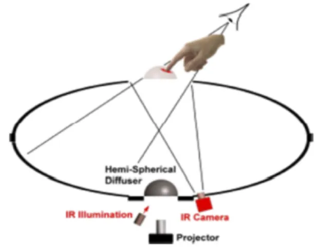
Figure 13: Sensing 3D volume using Infrared camera
Using IR, any 3D object placed at the bottom of the mirrors will be reimaged as floating on the display area. This object will be observed by an IR camera from below. This cam- era observes and can detect fingertips intersecting with the reimaged object. An important advantage of this technique is that it can distinguish between the finger touching the ob- ject and other fingers, because only the finger intersecting the reimaged object is IR illuminated. A video projector is used to render visible graphic outputs. An interesting example is shown in Figure14b, where a map of earth is projected and the user can spin the globe.
Figure 14: Vermeer: Interactions with 3D volume The main disadvantage of Vemeer remains the size of the 3D content which is displayed. Currently, the size is very small, only few centimeters. Authors consider as future work to im- prove and increase the size of the display. A possible solution is to increase the size of the parabolic mirrors. However, in- creasing the size of the parabolic mirrors directly affects the interactivity of the user since the 3D display volume becomes unreachable for the user.
CONCLUSION
In this seminar report we presented papers related to 3D in- teractive displays. We showed first the LightSpace, a project
that provides highly interactive surfaces but with 2D projec- tion. The rest of the projects were directly related to 3D interactive displays. First, the BiDi project makes use of LCDs with embedded optical sensors to capture gestures in front of the screen. This screen supports multi-touch and off- screen gestures with displayed 3D objects. However, BiDi screen does not support direct interaction with 3D content.
The HoloDesk project provides direct in-volume interactions with 3D virtual content. By using a Kinect camera to con- tinuously sense depth information, and an RGB camera to track user’s head position, HoloDesk provides correct per- spective of the 3D content. Although HoloDesk enables rich free realistic interactions, it suffers from limited viewpoint.
The last project, Vermeer provides 360 degree viewable dis- play and allows users to directly interact with 3D volume.
This project exploits the known optical illusion of parabolic mirrors to provide 360◦ view display. In order to perform motion objects and interaction from the user’s side, two dif- ferent techniques were presented: the first one using Kinect camera and the second technique using infrared cameras to detect finger contact with the volume.
As a conclusion, in the last few years 3D interactive displays have seen rapid enhancement. Considering the huge effort and investment in the research, it is likely that these proto- types and many other interactive 3D displays will become part of the everyday life.
REFERENCES
1. Raskar, R., Welch, G., Cutts, M., Lake, A., Stesin, L., and Fuchs, H. (1998). The Office of the Future: A Uni- fied Approach to Image-Based Modeling and Spatially Immersive Displays. In Proc. of ACM SIGGRAPH 1998.
2. Wilson, A. D., and Benko, H. Combining multiple depth cameras and projectors for interactions on, above and between surfaces. In Proc. ACM UIST 2010.
3. Hirsch, M, Lanman,D., Holtzman, H., Raskar, R. BiDi screen: a thin, depth-sensing LCD for 3D interaction using light fields. In Proc. of ACM SIGGRAPH, 2009.
4. Brown, C. J., Kato, H., Maeda, K., Hadwen, B. A continuous-grain silicon-system LCD with optical in- put function. IEEE J. of Solid-State Circuits 42, 2012.
5. Mulder, J. D., and Liere, R. V. The personal space sta- tion: Bringing interaction within reach. In Proc. VRIC, 2002.
6. Prachyabrued, M., and Borst, C. W. Dropping the ball:
Releasing a virtual grasp. In Proc. ACM VRST, 2011.
7. Hilliges, O., et al. HoloDesk: Direct 3D Interactions with a Situated See-Through Display. CHI12, May 510, 2012, Austin, Texas, USA.
8. A.Jones et al. Rendering for an Interactive360◦Light Field Display. In Proc. of ACM SIGGRAPH, 2007.
9. Butler, A., et al. Vermeer: Direct Interaction with a 360◦Viewable 3D Display. In Proc. ACM UIST, 2011.