Working Paper
RASSLE: Return Address Stack based Side-channel LEakage
Author(s):
Chakraborty, Anirban; Bhattacharya, Sarani; Alam, Manaar; Patranabis, Sikhar; Mukhopadhyay, Debdeep
Publication Date:
2021
Permanent Link:
https://doi.org/10.3929/ethz-b-000460069
Rights / License:
In Copyright - Non-Commercial Use Permitted
This page was generated automatically upon download from the ETH Zurich Research Collection. For more information please consult the Terms of use.
ETH Library
Side-channel LEakage
Anirban Chakraborty
1, Sarani Bhattacharya
2, Manaar Alam
1, Sikhar Patranabis
3and Debdeep Mukhopadhyay
11
Indian Institute of Technology Kharagpur, India,
{anirban.chakraborty,alam.manaar}@iitkgp.ac.in, debdeep@cse.iitkgp.ac.in
2
Katholieke Universiteit Leuven, Belgium, sarani.bhattacharya@esat.kuleuven.be
3
ETH Zürich, Switzerland, sikhar.patranabis@inf.ethz.ch
Abstract. Microarchitectural attacks on computing systems often stem from simple artefacts in the underlying architecture. In this paper, we focus on the Return Address Stack (RAS), a small hardware stack present in modern processors to reduce the branch miss penalty by storing the return addresses of each function call. The RAS is useful to handle specifically the branch predictions for the RET instructions which are not accurately predicted by the typical branch prediction units. In particular, we envisage a spy process who crafts an overflow condition in the RAS by filling it with arbitrary return addresses, and wrestles with a concurrent process to establish a timing side channel between them. We call this attack principle, RASSLE
1(Return Address Stack based Side-channel Leakage), which an adversary can launch on modern processors by first reverse engineering the RAS using a generic methodology exploiting the established timing channel. Subsequently, we show three concrete attack scenarios:
i) How a spy can establish a covert channel with another co-residing process? ii) How RASSLE can be utilized to determine the secret key of the P-384 curves in OpenSSL (v1.1.1 library)? iii) How an Elliptic Curve Digital Signature Algorithm (ECDSA) secret key on P-256 curve of OpenSSL can be revealed using Lattice Attack on partially leaked nonces with the aid of RASSLE? In this attack, we show that the OpenSSL implementation of scalar multiplication on this curve has varying number of add-and-sub function calls, which depends on the secret scalar bits. We demonstrate through several experiments that the number of add-and-sub function calls can be used to template the secret bit, which can be picked up by the spy using the principles of RASSLE. Finally, we demonstrate a full end-to-end attack on OpenSSL ECDSA using curve parameters of curve P-256. In this part of our experiments with RASSLE, we abuse the deadline scheduler policy to attain perfect synchronization between the spy and victim, without any aid of induced synchronization from the victim code.
This synchronization and timing leakage through RASSLE is sufficient to retrieve the Most Significant Bits (MSB) of the ephemeral nonces used while signature generation, from which we subsequently retrieve the secret signing key of the sender applying the Hidden Number Problem.
Keywords: Return Address Stack · Microarchitectural Attack · Template Matching
· OpenSSL ECC scalar multiplication · ECDSA P-256 · Lattice Reduction.
1 Introduction
The evolution of computer architecture has taken place through several inventions of sophisticated and ingenious techniques, like out-of-order execution, caching mechanism,
1RASSLEis a non-standard spelling for wrestle.
branch-prediction, speculative execution, and a host of other optimizations to maximize throughput and enhance performance. While it is imperative to imbibe and develop these artifacts in our modern-day machines, it is equally necessary to understand the security threats posed by these mechanisms, particularly on the execution of cryptographic programs operating on sensitive data. As the foremost criteria of these architectural optimizations have been performance, they need a closer investigation from the security point of view. With the growing impetus for security in applications where modern computing finds usages, a multitude of microarchitectural attacks have been unearthed by security researchers that exploit information leakage due to the functioning of these artifacts. These attacks have been shown to threaten the secret keys of cryptographic algorithms when run on these platforms, a risk that puts to threat several critical operations where these machines are expected to operate.
Some of the oldest attacks targeted the cache memories [Ber05, Per05, AKS07a, Aci07, BM06] where they tried to exploit the timing side-channel [Koc96] produced due to the presence of cache between very fast processor and a comparatively slow memory. More re- cent cache-based attacks can be categorized into three generalized techniques - Evict+Time [OST06], Prime+Probe [OST06], and Flush+Reload [YF14]. A number of variants of these attacks have been proposed over the years, which include defeating countermeasures like kernel address space-layout randomization (KASLR) [HWH13, CSH
+20, DKPT17], attacks on cryptographic protocols such as RSA [Per05, IGA
+15], AES [AKS07a, GII
+15, IES15], ECDSA [YB14, BH09], ECDH [GVY17], setting up covert channels on the cloud [RTSS09, ZJOR11], attacks exploiting performance degradation [ABF
+16], reading user inputs [GSM15, GMWM16, Hor16], etc. Another important microarchitectural com- ponent that has been the target of a multitude of attacks is the branch prediction unit (BPU). Ciphers like RSA, which contain conditional branches in their implementation, have been targeted by exploiting the BPU [AKS07b,ERAGP18,BM15]. Similarly, breaking KASLR [EPAG16] and setting up a covert channel have also been demonstrated using BPUs.
More recent attacks like Spectre [KHF
+19] and Meltdown [LSG
+18] exploit the speculative execution subsystem and out-of-order engine present in the CPU. Another class of attacks called Microarchitectural Data Sampling (MDS) (e.g. [VSMÖ
+19, MML
+19, SLM
+19]) surfaced more recently, which leak data across protection boundaries.
The Spectre attack exploits the speculative behaviour of modern processors to expose secret information that is otherwise inaccessible to the attacker. SpectreRSB [KKSAG18]
proposed a new variant of Spectre attack where the authors exploited the Return Address Stack (RAS) to cause speculative execution of payload gadgets and expose sensitive information. They showed multiple variants of their attack, where they manipulate the RAS in order to create a mismatch of the return addresses. They further implemented their attack on the Intel SGX [CD16] platform, where a malicious operating system corrupts the RAS to expose data out of the enclave by forcing mis-speculation. Concurrently [MR18]
proposed another attack, named ret2spec, abusing the RAS similarly to read user-level memory that should be inaccessible in the normal course. They proposed two variants of their attack - one where the attacker program poisons the RAS to coerce a co-located process to execute arbitrary code speculatively and another, where they leverage JIT (just-in-time) environment to read arbitrary memory in modern browsers. In a more general sense, both the papers [KKSAG18, MR18] try to leverage the fact that the RAS is a part of the speculative execution process and manipulate or poison the RAS in order to create mis-speculation.
In this paper, we propose a novel attack mechanism exploiting the Return Address
Stack (RAS) - a hardware entity in modern machines meant to improve the prediction for
RET instructions. We show how a spy can reverse-engineer the RAS to develop suitable
attack vectors. In particular, we show how a covert channel can be established by exploiting
the reverse-engineered knowledge of the RAS. Secondly, we show demonstrate one can
perform a timing side-channel attack by targeting the scalar multiplication on the P-384 curve in OpenSSL(v1.1.1g library). Finally, we extract the secret key from ECDSA on P-256 of OpenSSL using lattice reduction on partially leaked nonces. Collectively, we call the idea of the RAS based attack, as RASSLE, where the spy wrestles with a target code to launch effective timing attacks.
1.1 Motivation
RAS presents a side-channel artifact that has been comparatively less explored. It can fall into a class of branch prediction attacks, which can be effective even when a code is devoid of explicit loops. This is because it is related to function calls and returns from functions.
There has been no prior work that established timing channels exploiting the RAS, nor has shown the effective covert channels utilizing its presence in the computing system.
Moreover, due to the now well-known mitigating techniques against Spectre attacks, the reported mis-speculation attacks using RAS can be thwarted in modern processors [Tur18, KKSAG18, MR18]. This fact motivated us to look for other avenues through which the RAS can be exploited. As RAS has a fixed size, the number of return addresses of functions that can be stored in it is limited by its capacity. Now, in case of overflow or underflow conditions (explained later in Section 2), mispredictions can occur. These mispredictions lead to a timing penalty, revealing information of various categories - covert channels, secret keys, etc. It is worth mentioning that although SpectreRSB [KKSAG18]
proposes a similar attack setup where two colluding threads operate in synchronization;
the paper focuses on creating mispredictions and does not establish the evident covert channel that exists due to sharing of the RAS.
Finally, despite the common wisdom of writing cryptographic codes ensuring the independence of secret key, the paper mentions an exploit in the popular OpenSSL library on a standard elliptic curve, where the number of function calls (add -and-sub) is dependent on the secret key bits. The paper makes an effort to develop a template attack for determining the secret key by timing observations by a spy exploiting the RAS.
1.2 Our Contribution
In this work, we propose a new side-channel leakage source through RAS called RASSLE which, unlike existing works, does not mistrain the RAS or abuse the speculative execution engine. Rather, we utilize the timing channel created due to overfilled RAS, which eventually causes misprediction of the return address and leaks information about the control flow of a co-located process. Our main contributions are as follows:
• We reverse engineer the depth of RAS using timing information and provide a generic methodology that can be used for any processor.
• We particularly exploit the fact that overflowing RAS can trigger misprediction, ul- timately creating a timing side-channel. Based on the timing channel identified, we demonstrate how a covert channel can be established between a spy and a co-residing program by exploiting the RAS.
• We show an exploit in the ECC scalar multiplication of P-384 in OpenSSL, wherein the number of function calls is dependent on secret key bits. We show a template-based attack which the RASSLE spy can launch to deduce the secret key bits.
• We show how RASSLE can be adapted to a completely asynchronous running spy and victim, where the spy could manage to achieve one to one correspondence to the victim execution by tweaking the deadline scheduler policy from the user level. We develop this into a key-recovery attack on OpenSSL’s ECDSA signature scheme (P-256 curve-based).
In particular, we adopt well-known lattice-based techniques to recover the ECDSA
signing key from ephemeral nonces that are partially reconstructed using RASSLE.
1.3 Responsible Disclosure
While we found this efficiently working covert channel and timing vulnerability of OpenSSL P-384 and P-256 implementation in context to the shared Return Address Stacks, we have taken this opportunity to contact the security team of Intel and OpenSSL regarding the said vulnerability. We hope that by making this communication regarding this specific architectural design vulnerability to the security designers of processor manufacturing companies would lead to further collaborations in solving the problem together.
1.4 Organisation
The rest of the paper is organized as follows. Section 2 briefly discuses the working principle of RAS. Section 3 shows how to reverse engineers the RAS and introduces a novel timing side channel created thereof, based on which Section 4 proposes a proof-of-concept attack scenario. Section 5 shows how RASSLE can be utilized to perform template attack on P-384 curve in OpenSSL. Section 6 shows how to get asynchronous spy and victim processes to work using RASSLE, and subsequently demonstrates an attack on the ECDSA signature generation algorithm. Section 7 discusses potential countermeasures against our proposed attacks. Finally, Section 8 concludes the paper.
Additional material presented for completeness includes details of the scalar multiplica- tion implementation in OpenSSL (Appendix A), background on ECDSA (Appendix B) and cryptanalysis of ECDSA using lattice techniques (Appendix C).
2 Return Address Stack (RAS)
In this section, we start with a general understanding of return addresses and how frequently used return addresses are stored in a specialized micro-architectural hardware component called RAS. Return instructions are a special type of indirect branch instructions that might get called from different program locations, but the target address will remain the same. For example, the printf() function in GNU-C library can be called from different functions of a program. Every time the same library subroutine will be invoked, and the same set of instructions will be executed. However, since they are called from different program locations, the return addresses for each corresponding function call will be different.
Now considering a speculative execution environment, for each return statement, the processor must predict the return address (usually the next instruction after the call statement), which the program counter (PC) must contain. Generally, the Branch Target Buffer (BTB) stores a mapping between the branch source and the target address for other indirect branches. But in the case of return instructions, the BTB will often mispredict since the same function can be called from different locations and thus have different return addresses. Thus to improve the prediction rate, modern processors deploy hardware-based stack call Return Address Buffer, or equivalently, RAS.
Return addresses are generally stored in the software stack, which is maintained in the
main memory. In order to keep the return addresses closer to the processor, processor
engineers incorporated hardware-based RAS, which essentially alleviates the high latency
experienced when the return address is fetched from the main memory. The processor on
encountering a call statement pushes the return address (the address of the next instruction
in program order) to the RAS, and when a corresponding matching return statement is
encountered, the processor speculatively executes the instruction stored at the address
pointed by the top of RAS. At a later stage in the pipeline, the processor matches the
return address with the one stored in the software stack. If both the addresses match,
the execution is continued; else, discarded. Given that the return addresses are stored on
the stack, the processor refers to the RAS every time it encounters a return statement.
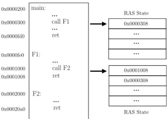
RAS State RAS State
0x0001008
...
...
0x0000308
0x00020a0 0x0002000 0x0001008 0x0001000 0x0000fe0 0x0000fd0 0x0000300 0x0000200
ret ...
F2:
ret ...
call F2 F1:
ret ...
...
call F1 main:
...
...
...
0x0000308
Figure 1: Example of function call and its effect on RAS.
code main:
call F17 ret F17:
call F16 ret
F2:
call F1 ret F1: ...
ret
...
F17 return main return
...
...
...
...
After executing call F17
RAS State
F2 return F3 return
...
After executing call F2
RAS State F4 return
F16 return F17 return
F1 return F2 return
...
After executing call F1
RAS State F3 return
F15 return F16 return
F17 return
Figure 2: Reverse Engineering Return Address Stack.
Without such a hardware stack, the processor would have to spend multiple clock cycles to fetch the return address from main memory.
2.1 Working Principle
RAS is generally implemented as circular LIFO (Last In, First Out) stacks, which can
store a fixed number of entries of return addresses. When a function call is executed with
the stack already at its full capacity, the new entry (return address) is inserted at the
top of the stack, and the oldest entry (from the bottom of the stack) is discarded. This
is known as overflow condition. Similarly, if a series of overflow conditions drive out the
valid return addresses from the stack, it causes an underflow condition where there are no
entries available in the stack [SAMC98]. An example of the working principle of RAS is
shown in Fig. 1. Consider a program consisting of main function and two function calls
F1 and F2. Corresponding addresses of the instructions in memory are also depicted
beside the instructions in Fig. 1. When the function F1 is called, the address for its next
instruction is pushed onto the top of the stack. Inside F1, another function F2 is getting
called which again pushes its return address onto the top of the stack. Now, whenever a
return statement is encountered, the address from the top of the stack is popped and is
used as a reference for the next instruction to be fetched in the pipeline.
3 Delving into processor specific RAS reverse engineering
In this section, we develop a generic methodology to reverse engineer the capacity of Return Address Stack. The number of entries that RAS can accommodate varies for different families of processors. In case of deeply nested calls (for example, recursions), the return addresses are pushed onto the stack for each call statement. If the stack was already full, the oldest entry is discarded from the bottom, and the newest entry is added to the top of the stack. Therefore, during subsequent returns, the addresses present in the stack will be fetched quickly from this specialized hardware, thereby aiding the performance. Whereas, the return addresses, which were pushed off the stack due to overflow condition, becomes unavailable. This situation forces the processor to stall for multiple clock cycles in order to decode the actual return address from the software stack (stored in main memory and subsequently in the cache memory hierarchy), which incurs a significant latency and results in a considerable increase in the execution time. The fact that an overflow condition in RAS leads to an increase in execution time helps in reverse-engineering the length of the stack in different processors.
3.1 Observing Timing Differences over Recursive Function Calls
In our experimental setup, we show the results on Intel i7 7700 running Ubuntu 16.04;
however, the same experiment can also be conducted on other architectures. The typical size of Return Address Stack in contemporary processors are 16, 32, and 64. Fig. 2 shows a pictorial representation of the reverse engineering approach. The idea is to execute several function calls in a nested fashion such that each function call pushes a return address onto the stack and simultaneously checking the execution time after each function performs a return. The steps may be summarized as follows:
• We start with an arbitrary number of nested function calls (without loss of generality, say 18) and check the difference in execution time for 18 calls and 17 calls separately.
This provides us an estimate of the timing for the outermost function (function 18 in this case). We run the experiment for 100, 000 times (in order to ensure consistency of the measurements) and calculate the mean difference in execution time for 18
thfunction and 17
thfunction. The difference turns out to be 40.52 clock cycles (Fig. 3a).
• We repeat the same experiment for 17 nested calls and check the mean difference at depth 17
thand 16
thfunction call. The difference in execution time was close to the earlier one, 44.26 clock cycles (Fig. 3a).
• Next, we reduce the function depth by 1 and repeat the experiment. The difference in timing for depth 16
thand 15
thcall was observed to be 21.43 clock cycles (Fig. 3a), which is considerably less than the previous two values.
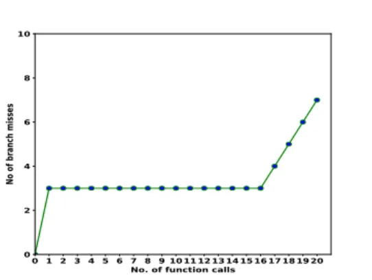
As shown in Fig. 2, the reason for the decrease in execution time is that when the depth of nested function calls is 16 or less, the processor gets all the return address from the RAS and therefore takes considerably less time to complete execution. This signifies that on our target system, the RAS can hold up to 16 entries. However, if the depth of the nested calls is more than 16, the oldest return address will be written off (removed) from the stack. Therefore when a corresponding return statement is executed, the processor will have to stall for multiple cycles to fetch the return address from the software stack stored in the main memory.
3.2 Validating Results using Hardware Performance Counters
In the previous sub-section, we reverse-engineered the size of the RAS using timing
information. Although timing information is based on the number of CPU cycles elapsed
f7-f8 f8-f9f9-f10f10-f11f11-f12f12-f13f13-f14f14-f15f15-f16f16-f17f17-f18f18-f19f19-f20f20-f21 i-th and (i - 1)th function call 15
20 25 30 35 40 45
Difference of time of execution
(a) Timing difference (in clock cycles) for i
thand (i − 1)
thfunction calls
0 1 2 3 4 5 6 7 8 9 1011121314151617181920 No. of function calls
0 2 4 6 8 10
No of branch misses
(b) Number of branch misses w.r.t depth of function calls
Figure 3: Variation of (a) timing and (b) branch misses shows the capacity of RAS.
during the execution of a particular process, the values can sometimes be influenced or disturbed by the interaction among other processes and components of micro-architecture.
Therefore, we validate the results obtained by timing information using information from Hardware Performance Counters (HPCs).
HPCs are a set of special-purpose registers present in modern microprocessors. These counters come in handy for monitoring and measuring various hardware and software events during process execution. Although initially designed as a profiling tool to optimize programs and applications, HPCs have been recently used for security purposes, both in offensive and defensive ways. In this paper, we utilize the perf-event profiling tool to verify the results obtained in the previous sub-section. It must be noted that perf-event can only be accessed from administrative privilege. Therefore, we use HPC only for validation purpose and not for the attack.
In a speculative execution environment, the target address for a return instruction is predicted by referring to RAS and matched with the actual value stored in the main memory much later in the pipeline. Therefore, any wrongly predicted address or an underflow/overflow condition in the RAS will result in a branch miss event. Branch misses can be pretty accurately measured for a process using the perf-event tool in Linux. The event PERF_COUNT_HW_BRANCH_MISSES records the number of branch misses under the PERF_TYPE_HARDWARE type event. We use ioctl calls to query the performance counters.
Incidentally, we found out that for the inner 16 functions, the number of branch misses is 2 while for the 17
thfunction, the number of branch misses becomes 3 and further increases by 1 for each unit increment in function depth. Fig 3b shows how the change in depth of nested function calls affects the branch miss statistics due to the presence of RAS. This verifies our claim that on our setup, RAS can hold up to 16 entries. Additionally, this reverse engineering method can be easily scaled up and generalized for any target setup.
4 RASSLE: Establishing a covert channel through RAS
In this section, we exploit the fact that an overflowing RAS can result in an increase in
execution time, and this difference in timing can be observed by a co-located process to
establish a covert channel between two processes.
4.1 Contention-based Timing Channel over RAS
Although RAS is designed to enhance the overall performance of the processor, the security implication of such a capacity-bound hardware stack has not been explored in depth before.
We explore and analyze the timing channel created through RAS and its implication on co-located processes for the first time. We present RASSLE - which literally means to wrestle or scuffle - where an adversary wrestles with a co-located victim process to occupy the RAS and, in the course, learns valuable information regarding the control flow of the victim process. For example:
• Consider two processes - Process A and Process B - running simultaneously on the same logical core on a system.
• Process A executes a series of N nested function calls (shown in the adjoining figure), where function F1 calls F2, which in turn calls F3 and so on. Therefore, for each function call, an entry is inserted to the top of the stack. Choose N such that the entire stack gets filled with the return addresses of the corresponding function calls.
...
do something ret FN:
call FN ret FN-1:
call F3 ret F2:
call F2 ret F1:
call F1 ret main:
Now, as the innermost function FN executes the return instruction, the topmost entry gets popped out, and the stack will contain the remaining (N − 1) entries. In order to avoid that and keep the stack occupied, we voluntarily let the process A cede the control of the CPU (yield) just before executing the return statement inside the innermost function (FN ). The situation becomes interesting from the security point of view when we consider process B running simultaneously on the same CPU core. Consider the following sequence of events - 1 Once again, process A executes N (large enough to fill the RAS) nested function calls. Inside the innermost function, it yields the CPU before executing the return instruction. Therefore, the entire RAS is
filled with return addresses of process A with the return address for the innermost function at the top of the stack. 2 In this scenario, if we allow process B to execute some function, or in more general terms, it executes M (could be as small as 1) functions in a nested fashion. As both processes A and B share the same RAS, the return address from process B will be pushed onto the stack, whereas N − M number of return addresses for process A will be pushed out from the end of the stack
2. This results in an underflow condition where some valid return addresses have been pushed out of the stack. 3 As the control of the CPU returns to process A, it executes all the return instructions and measures the time elapsed for the execution of each function. Due to the introduction of M return addresses by process B, process A will experience a considerable increase in execution time between (N − M )
thand (N − M + 1)
thfunctions and also for all the subsequent functions.
Therefore, paired up with the timing observation experiment in the earlier section, RAS can be exploited by Process A to understand the control flow of Process B. This timing difference could also be converted to a very reliable covert channel between these two processes. Moreover, this seemingly simple timing side-channel can have bigger security implications in the context of security-critical applications. To better understand the security threats posed by RAS, we develop a threat model and introduce our proof-of- concept implementation in the following subsections.
4.2 Assumptions on the Threat Model
We consider a multi-user environment running on a Linux-based operating system, where multiple concurrent processes are sharing the hardware. The adversary does not need any special privileges. However, it does have a requirement to relinquish the CPU after filling
2As the RAS is implemented as a FIFO circular queue, the entry of new address will push the last address out of the stack.
the RAS to its full capacity. This could be achieved by executing system calls such as sched_yield
3and acquire CPU cycles using rdtscp
4instruction. Both the instructions can be executed from user-level privilege. This exploit requires that the victim and the adversary to operate on the same logical core. This can be achieved using taskset, which is a common assumption in similar attack settings [KGGY20].
4.3 Establishing the Covert Channel
We present our proof-of-concept (POC) implementation using RASSLE on a toy example.
Similar to the discussion in the earlier subsection, here we consider two processes and name them as transmitter and receiver. Consider the sample program of the transmitter process as given in Listing. 1. In this program, the transmitter reads from a string of binary characters (‘0’ or ‘1’) in a loop and based on the value of the character processed, either executes a function (func) or does nothing. Also it is worth mentioning that we deliberately force the transmitter process to yield the CPU at the end of each loop such that the adversary process can take control and run its exploits. This is done in order to better synchronise the transmitter and the receiver.
char r[] = "11010101010000001110001111";
for (int i = 0; i < sizeof(r)/sizeof(r[0]); i++) { char c = *(r + i);
if (c == '1') call func() sched_yield();
}
Listing 1: Sample transmitter program In our POC, the covert channel is established as follows:
• Receiver process: calls N nested functions in a loop to fill up the entire RAS
5. Inside the deepest function (i.e., 16
thfunction in our case), the receiver yields the CPU to the transmitter just before executing any return statement.
• Transmitter process: running on the same processor core as that of the receiver, takes control of the CPU. Depending on the value of the bit processed, the transmitter will either call another function, or does nothing.
– Suppose, the bit processed is ‘1’; the transmitter program will then call the function func and as a result, the return address, i.e., the address of the subsequent instruction after the call statement will be pushed onto the stack. Since the stack was already full, the entry of new address will push the oldest entry out of the stack.
– While on processing a ‘0’, there is no impact on the RAS state. The RAS state remains unaltered as the receiver has left it.
• Receiver process: At this point, the control of the CPU is moved to the receiver which will start executing the un-finished return commands by referencing the addresses stored in the stack. Starting from the deepest function (16
thfunction), all the return statements will be executed by referring to the addresses stored in the stack. Timing latency in the outer-most function makes the covert channel complete.
3Note thatsched_yieldis a system function in Linux, which causes the calling thread to relinquish the CPU.
4Therdtscpinstruction reads the current value of the processor’s time-stamp counter.
5The machine we did our experiment on had RAS of capacity 16.
0 5 10 15 20 25 Bit Index
2190 2200 2210 2220 2230
Timing values in clock cycles
threshold
Figure 4: Timing values observed through RASSLE reveals the information transmitted. The values above the threshold indicate a ‘1’ and values below the threshold indicate ‘0’. Thus it reads
"00010101010000001110001111". Apart from the first two bits, the rest of the character stream can be constructed without any error.
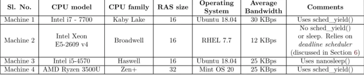
Table 1: Comparison of POC covert channel on various systems
Sl. No. CPU model CPU family RAS size Operating System
Average
Bandwidth Comments Machine 1 Intel i7 - 7700 Kaby Lake 16 Ubuntu 18.04 30 KBps Uses sched_yield()
Machine 2 Intel Xeon
E5-2609 v4 Broadwell 16 RHEL 7.7 12 KBps
No sched_yield() or sleep. Relies on deadline scheduler (discussed in Section6) Machine 3 Intel i5-4570 Haswell 16 Ubuntu 18.04 25 KBps Uses nanosleep() Machine 4 AMD Ryzen 3500U Zen+ 32 Mint OS 20 25 KBps Uses sched_yield()
Receiving a ‘1’: CPU while executing the final return statement will encounter a stack underflow situation and thereby require comparatively more time to complete the process.
This difference in timing due to expulsion of return address from the stack will be the basis to determine whether the transmitter processed a ‘0’ or a ‘1’.
Receiving a ‘0’: This is inferred when no extra latency can be observed.
Fig 4 shows the distribution of timing values observed by the receiver. The threshold is empirically selected and the timing values above the threshold denote a bit ‘1’ and below the threshold denote a bit ‘0’. In our experiments, the information transmitted through the covert channel had an accuracy of 75% to 85%.
In the POC just described, we assumed that the transmitter yields the CPU at the end of each iteration. However, this is a very restricted model because, in practice, it will be highly unlikely that an unaware transmitter process will yield the CPU after every iteration. Fortunately, in our experiments, we found out that using sleep has similar effect as sched_yield. We replaced sched_yield with nanosleep and put some delay (in nanoseconds) at the end of every iteration. Similar to the attack proposed earlier, the transmitter processes a character stream of 0s and 1s in a loop and if the bit is ‘1’, it calls the function func. However, at the end of each iteration it goes into sleep for a short predefined duration. When the process goes into sleeping state, the control of the CPU moves to the other waiting processes - the receiver process in this case. Table 1 quotes the RAS size and bandwidth achieved by the POC and also the constraints on a few interesting setups where we made our POC to work.
5 Case Study on OpenSSL ECC Scalar Multiplication
In the previous section, we demonstrated how RASSLE can be utilized to leak information
about the control flow of another process. The POC we proposed is a generic attack
technique which exploits the timing side channel to precisely extract the secret information hidden within the victim program. However, such naïve implementations are rarely seen in modern day security-critical cryptographic libraries. Therefore, to demonstrate RASSLE on a real-world setting, we target the scalar multiplication operation in NIST P-384 curve from OpenSSL. This curve has been specified by the NSA Suite B Cryptography as the recommended elliptic curve to be used in ECDSA and ECDH algorithms [Nat15, X9.03].
5.1 Elliptic Curve Cryptography and OpenSSL
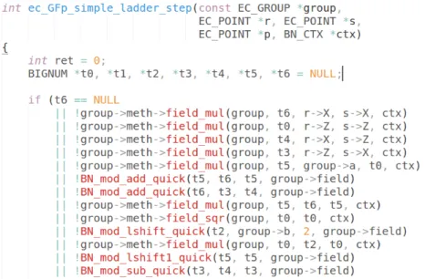
Elliptic Curve Cryptography (ECC) is one of the most widely used asymmetric key algorithms based on the algebraic properties of elliptic curves over finite fields. Point multiplication or scalar multiplication is the fundamental and security-critical operation in ECC which computes Q = [k]P, where k is an n-bit secret scalar and Q and P are points on the elliptic curve. The security of ECC is defined by the intractability of determining the scalar k given both the points and the curve parameters. The scalar multiplication in OpenSSL is implemented using Montgomery ladder with conditional swaps and Non-Adjacent Form (wNAF) for scalar representation. The scalar k is transformed to its corresponding wNAF representation and based on this representation, a series of double and add operations are executed to perform the multiplication. These operations are further implemented by a series of BN_add and BN_sub functions (more details in Appendix A). The aggregate number of such calls are not constant, and are dependent on both the value of secret scalar and the input basepoint. Therefore, the number of times the BN_add and BN_sub functions are executed depend on the affine coordinates of the EC point, as well as the value of the secret scalar. OpenSSL also provides a support for point randomization, where the EC points are randomized in every call to the ECC function.
However, in this particular work, we have demonstrated a chosen plaintext attack with the basic timing observations which demands full control on selecting the input points to the ECC operation. Thus we assume that such countermeasures have been disabled.
5.2 Timing Variation Observed through RASSLE
Similar to the lines of our POC described in Section 4, we set up the spy process to monitor the timing values. By using the reverse engineering methodology described in Section 3, the spy determines the capacity (say, n) of the RAS in the target system. Next the spy, attached to a specific CPU core, continuously executes n nested function calls in a repeated manner. Inside the n
thfunction, i.e., the innermost function, the spy deliberately yields the CPU before executing the return statement. In other words, the spy fills up the entire RAS with the return addresses of its n functions and cedes the control of the CPU without executing any return statement. Simultaneously on the same CPU core, a victim process is executing ECC scalar multiplication operation using the OpenSSL library. It is worth mentioning in this context that the POC attack assumes that the victim intentionally yields the CPU after every iteration and the attack on OpenSSL ECC is presented as a use-case of the POC. Therefore, we assume the victim executes a nanosleep or sched_yield
6after each iteration of the scalar multiplication operation.
The objective of the spy program is to determine the number of calls made to BN_add and BN_sub functions by the Montgomery ladder implementation for each bit of the secret scalar. The spy program is running continuously and measuring its own execution time to check whether any of its return addresses have been pushed out of the stack. As the victim process executes the scalar multiplication in a bit by bit manner, it makes a number of calls to BN_add and BN_sub functions depending on the value of the scalar bit and the affine co-ordinates of the elliptic curve point. As usual, the function calls made by the
6In the later part, we will relax this requirement by abusing thedeadline schedulerto perform the synchronisation between victim and the spy.
scalar multiplication operation pushes the return addresses of the corresponding functions into the RAS. As the RAS is being shared by both victim and spy, the entry of new return addresses removes equal number of entries of the spy. Therefore, the spy which is running in parallel is able to precisely deduce the total number of BN_add and BN_sub functions, being called for each bit of the scalar.
5.3 Template Attack on ECC Scalar Multiplication
Template Attacks are profiled side channel attacks where an attacker builds a profile using different combinations of the secret key on a particular device and then matches the template with the actual values gathered from the target application on a similar device.
We discussed how RASSLE can be used to determine the total number of additions and subtractions performed per bit of the scalar. Using this information, we aim to perform a template attack on the widely popular OpenSSL implementation of the NSA recommended elliptic curve P-384.
In this part of the exploit, we follow an iterative linear attack procedure. The adversary iteratively progresses through the bits of the secret scalar (key) starting from the most significant bit (msb) to the least significant bit(lsb). At a particular instance, the adversary targets the i
thbit of the secret scalar, given the assumption that the adversary already knows the first (i − 1) bits, and further aims to retrieve the subsequent bits one by one.
Therefore, the adversary needs to generate new set of templates for each bit position and correctly deduce that particular bit in order to proceed with the following bits. We also assume that the attacker is aware of the structure of the algorithm under attack, since the OpenSSL implementation codes are publicly available, making template formation on EC curve behavior used in the scalar multiplication reasonable.
During the template building phase, the attacker simulates the number of BN_add and BN_sub function calls for each bit. As the number of BN_add and BN_sub function calls depend on the particular bit being processed and the affine coordinates of the curve point, the attacker builds the templates for each bit based on the total number of BN_add and BN_sub functions executed for a fixed set of input plaintexts. This fixed set of plaintexts will be used by the attacker for both template generation and matching phase. More precisely, for any particular bit, say i
thbit, 1 the attacker performs point multiplication using a set of unique inputs (curve points) fixing the i
thbit to be both ‘0’ and ‘1’, we denote this as G
0and G
1. 2 Next, for each input, the attacker estimates the total number of addition (BN_add) and subtraction (BN_sub) function calls made by the ECC program for i
thbit assuming its value to be both 0 and 1. 3 Simultaneously, the spy process measures the execution time using RASSLE. Therefore, the attacker gathers two sets of information - total number of BN_add and BN_sub and timing information for each bit.
5.3.1 Template Building Phase
For simplicity, we introduce an encoding scheme to represent the total number of BN_add and BN_sub function calls as unique classes. Suppose, for a particular input and i
thbit, the Montgomery ladder of the scalar multiplication operation executes X BN_sub() and Y BN_add() function calls. We represent this class as (X Y). Based on the classes, we segregate the corresponding inputs and the associated timing values, i.e., we create hypothetical BIN corresponding to each class which contains the corresponding plaintext and the timing value observed from the spy. For example, fixing the i
thbit to be 0 yields:
(X Y )
G0: inputs which simulate to have X BN_sub() and Y BN_add() function calls.
BIN
G(XY)0: timing values corresponding to inputs in (XY )
G0Similar classification can be applied for (X Y)
G1and BIN
G(XY)1for G
1. Further, we
calculate the first order moments for each BIN
G(XY)0, BIN
G(XY)1to form our set of candidate
2000 3000 4000 5000 6000 7000 8000 9000 Timing values in clock cycles
0.0000 0.0002 0.0004 0.0006 0.0008
Normal distribution
class 91 class 102 class 103 class 104 class 105 class 81 class 85 class 84 class 83 class 95
(a) Distribution of all bins
4000 5000 6000 7000
Timing values in clock cycles 0.0000
0.0001 0.0002 0.0003 0.0004 0.0005 0.0006 0.0007 0.0008
Normal distribution
class 83 class 95
(b) Distribution of two selected bins Figure 5: Template formation phase: Distribution of timing observed using RASSLE for (10m + n) classes where m = no. of subtraction and n = no. of addition.
templates. Fig 5(a) shows an example of a candidate template with distribution for multiple bins for a particular bit of the key. Depending on the set of plaintexts, the number of unique classes can vary. In our experiments, we found that the classes belong in the range 81 to 85, 90 to 96 and 100 to 106. So typically number of BN_sub function calls varies between 8 to 10 and number of BN_add function calls vary between 0 to 6.
As already mentioned, each class corresponds to a unique BIN which contains the associated plaintexts and the mean and standard deviation values of all the corresponding timing values. Out of these multiple BIN s, the attacker selects a pair which contains a relatively high number of inputs, i.e., sets with high cardinality and non-overlapping timing distributions. In our experiments, we performed the template building phase using 10, 000 plaintexts, which we found to be enough to derive a reliable consistent statistic.
We empirically selected two bins such that each one contains more than 150 plaintexts and there is a visible difference in their mean statistic. An example of such a pair of BIN s is shown in Fig 5(b). For each bit, the entire template building phase took approximately 2 hours in our experimental setup. It must be noted in this context that for each bit, the template building phase will generate a whole lot of BIN s, among them selection of two appropriate bins will qualify as good templates. Therefore, at the end of the template generation phase, we will have four BIN s as our template - comprising of two fairly separated distributions based on the timing templates from each of (X Y)
G0and (X Y)
G1from the simulation when the i
thbit is 0 and 1.
5.3.2 Template Matching Phase
In template matching phase, we aim to predict the correct value of the i
thbit using the templates generated assuming the bit to be 0 and 1. While template generation is considered to be an offline phase, where the attacker simulates the scalar multiplication operation to build suitable templates, the matching phase is rather online where the only available information to the attacker is the timing value observed through RASSLE corresponding to each key bit. At the end of the template generation phase, the attacker has four BIN s - two for corresponding bit assumed to be 0 and two for bit assumed as 1.
Now, the attacker observes the encryption process once again using only those inputs that were associated with these four selected classes. The crux of template matching lies in the fact that the timing values for correct i
thbit matches with either of the two set of templates, but not both. If the observed timing measurements over the correct bit correlates with the template generated for G
0, then the actual value of the secret bit is revealed to be 0; else the matching works for the templates for G
1.
Similar to the generation phase, the attacker encrypts the selected set of inputs and
records the timing values observed by spy process using RASSLE. Once the online data
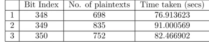
Table 2: No. of plaintexts and total time taken for the bit indices 348, 349 and 350 during template matching phase.
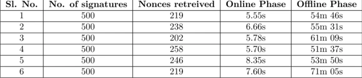
Bit Index No. of plaintexts Time taken (secs)
1 348 698 76.913623
2 349 835 91.000569
3 350 752 82.466902
acquisition step is complete, the timing values are placed into one of the four BIN s based on the plaintexts. Once the segregation of timing values into the appropriate BIN s is complete, we take the mean and standard deviation for each of the four bins and plot the distributions, similar to the generation phase. Out of the four bins, only two bins will correspond to the actual template, thereby revealing the actual value of the bit.
5.4 Experimental Validation
We performed our experiments on Intel i7-7700 powered by Ubuntu 18.04 (kernel 4.15.0).
We assume that the attacker and the victim are co-located on the same core
7, therefore sharing the same RAS for their operations. The RAS in our experimental setup has a capacity of 16, i.e., it can hold upto 16 return addresses. The spy program continuously fills up the RAS with 16 nested function calls and measures the execution time. The victim process executes the Montgomery ladder implemented using conditional swaps for each bit of the secret scalar.
Now, suppose for i
thbit of the secret scalar, the ladder executes m BN_add functions and n BN_sub functions. These (m + n) function calls pushes their corresponding return addresses which in turn forces the older entries out of the stack. This eventually results in increased execution time for the return statements of the spy process. The spy process observes the difference in execution times of all the 16 functions and observes a spike in timing value due to underflowing of the RAS.
Assuming the attacker knows the first (i − 1) bits, in the template generation phase, we run the scalar multiplication using a fixed set of 10, 000 plaintexts. These many inputs were chosen for no particular reason, but to make sure we get a significant consistent statistic for each of the template classes. As described earlier, the adversary uses the simulated number of BN_add and BN_sub function calls executed for the i
thbit to form the BIN s from their observed timing values through RASSLE. Similar to the template generation procedure, in the template matching phase we decide on the correct guess by segregating the observed timing values into appropriate bins based on the plaintext. Fig 6 shows the results of the template generation and matching process for 350
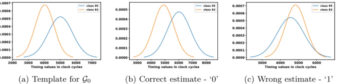
thbit. Fig 6(a) shows the distribution of the selected template. The classes 95 and 83 provides a stark difference in their distributions and thus we selected these two classes as our template.
Fig 6(b) and (c) shows the distributions of the aforementioned classes (or bins) for the correct estimate (0) and wrong estimate (1) of the bit value respectively. As evident from the figures, the distribution of the correct estimate matches with the actual template for the same pair of classes. Similarly, Fig 7 shows the results of another instance of template generation and matching process for 348
thbit for selected classes, correct estimate and the wrong estimate. Table 2 shows the number of plaintext used and total time taken in template matching phase for three consecutive bits.
6 Synchronization in a Purely Asynchronous Setup
The attack on OpenSSL ECC scalar multiplication presented in Section 5 demonstrates how RASSLE can be utilized to leak information about the control flow of another process. In
7This can be easily achieved from user-space usingtasksetcommand.
2000 3000 4000 5000 6000 7000 Timing values in clock cycles 0.0000
0.0001 0.0002 0.0003 0.0004 0.0005 0.0006 0.0007
Normal distribution
class 95 class 83
(a) Template for G
03000 4000 5000 6000 7000 8000 Timing values in clock cycles 0.0000
0.0001 0.0002 0.0003 0.0004 0.0005
Normal distribution
class 95 class 83
(b) Correct estimate - ‘0’
3000 4000 5000 6000 Timing values in clock cycles 0.0000
0.0001 0.0002 0.0003 0.0004 0.0005 0.0006 0.0007
Normal distribution
class 95 class 83
(c) Wrong estimate - ‘1’
Figure 6: Template matching for bit index 350.
2000 3000 4000 5000 6000 7000 8000 Timing values in clock cycles 0.0000
0.0001 0.0002 0.0003 0.0004 0.0005
Normal distribution
class 82 class 95
(a) Template for G
12000 3000 4000 5000 6000 7000 8000 Timing values in clock cycles 0.0000
0.0001 0.0002 0.0003 0.0004 0.0005
Normal distribution
class 82 class 95
(b) Correct estimate - ‘1’
3000 4000 5000 6000 7000 8000 Timing values in clock cycles 0.0000
0.0001 0.0002 0.0003 0.0004 0.0005 0.0006
Normal distribution
class 82 class 95
(c) Wrong estimate - ‘0’
Figure 7: Template matching for bit index 348.
this section, we present another use case of RASSLE in which a spy running simultaneously with victim process on the same core can precisely achieve synchronization by abusing the operating system’s scheduler policy, and collect timing information at fine granular steps which is enough to retrieve ephemeral keys from ECDSA implementation of OpenSSL.
6.1 Assumptions on the Threat Model
We would continue with the earlier assumption that the spy and victim process start their execution in the same logical core. However, unlike the victim code modification requirement mentioned in Section 5, in this scenario, the victim code does not need any extra synchronization aid, which makes the attack scenario realistic. A user only needs CAP_SYS_NICE capability to launch the attack from userspace. This is a reasonable assumption in a multi-user environment, since a user can optimize the parameters of the deadline scheduler (discussed in next subsection) to achieve maximum performance benefit for its “own task”
8. We execute both victim process and spy process simultaneously on a server-environment built on Intel Xeon CPU E5-2609 v4 (Broadwell) running Red Hat Enterprise Linux Server 7.7 (kernel 3.10.0-1062.9.1.el7.x86_64).
6.2 Getting Synchronization to work with the Deadline Scheduler
Most Linux-based operating systems offer a number of scheduling policies, which are crucial artifacts for controlling two asynchronous processes’ execution. Among the available policies, the deadline scheduler is particularly interesting because it imposes a “deadline”
on operations to prevent starvation of processes. In the deadline scheduler, each request by a process to access a system resource has an expiration time. A process holding a system resource does not need to be forcefully preempted, as the deadline scheduler automatically preempts it from the CPU after its request expiration time.
8CAP_SYS_NICEseemingly assists performance-tuning in server-environments, and has no known security- implications for the deadline-scheduler.
The operation of deadline scheduler depends on three parameters, namely ‘runtime’,
‘period’, and ‘deadline’. These parameters can be adjusted using chrt command, which can be executed from user-level privilege by acquiring CAP_SYS_NICE permission
9. A normal user who obtains the CAP_SYS_NICE permission, does not gain any elevated privilege apart from adjusting the deadline scheduler parameters. Obtaining scheduling privilege for user- level processes is practical in multiple real-life scenarios, where a normal user can use the privilege to efficiently utilize system resources for better performance. We observed that the covert channel described in Section 4.3 works in the presence of deadline scheduler
10by choosing appropriate parameters instead of using sched_yield() or nanosleep(). The command to run an <executable> using deadline scheduler is as follows:
chrt -d –sched-runtime t
1–sched-deadline t
2–sched-period t
30 <executable>
where, t
1, t
2, and t
3are the parameter values for ‘runtime’, ‘deadline’, and ‘period’
respectively. The kernel only allows scheduling with t
1≤ t
2≤ t
3. The usual practice is to set sched-runtime to some value greater than the average execution time of a task.
We estimate the average execution time of each iteration of the target executable (ECC Montgomery ladder in this case) in terms of CPU clock cycles and convert the values into nanoseconds using CPU clock frequency. We set t
1with the obtained value in nanoseconds.
Further, we set the parameter sched-deadline to a value t
2= t
1+ δ such that the ECC process leaves the CPU after execution of a single Montgomery ladder iteration. We set the parameter sched-period to a value t
3= 2 × t
1. The reason for such an assignment is discussed later in this section. It should be noted that the procedure described here considers no change in the victim code and requires no use of sched_yield() or nop or nanosleep() in the victim executable to preempt it from CPU.
In the proposed approach, a spy works in two phases - 1 it fills up the Return Address Stack (RAS) and cedes control of the CPU; 2 it probes the RAS by executing return statements after the victim has finished its scheduled operation. The spy process also uses multiple nop instructions such that operations in 1 takes approximately equivalent time to that of one iteration of the ECC Montgomery ladder. The reason behind the use of nop instructions in the spy process is that the victim and the spy can then be executed with a single sched-runtime parameter of the deadline scheduler. We also use sched_yield() at the end of 1 (i.e., in the spy process) to relinquish CPU control to the victim in order to ensure that the RAS remains full with the return addresses of the spy. As both spy and victim are running with the same ‘runtime’, the deadline scheduler preempts the victim process after one iteration of the ECC Montgomery ladder and gives the control of the CPU back to spy. The spy now probes the RAS by executing the return addresses, observes the execution timing through RASSLE, and again fills up the RAS. The sched-period signifies the periodicity of the task, which is set equal to 2 × t
1to target each iteration of the ECC Montgomery ladder. In our experiments, we used t
1= 3600, t
2= 3700, and t
3= 7200 to validate our proposed approach in the setup discussed in Section 6.1. We performed empirical parameter-optimizations to achieve a reasonable success-rate on the target platform.
6.3 Case-study on ECDSA Signature Generation Algorithm
In this section, we present a case study to illustrate how our attack strategy may be deployed to break the security of ECDSA [X9.03] - a widely used digital signature algorithm that uses Elliptic Curve Cryptography (see Appendix B for details). Our aim is to recover the secret signing key from an implementation of the ECDSA signing algorithm.
At a high level, the attack strategy against ECDSA can be divided into two steps:
9The permission can be provided to a user usingsetcap cap_sys_nice+ep /usr/bin/chrt.
10In order to inspect the underline scheduler in the working system one can use cat /sys/block/sda/queue/scheduler.
• Step-1 (online): In this online step, we use our RASSLE-based attack strategy to perform a targeted recovery of a fraction of the most significant bits of the nonces sampled by the ECDSA signing algorithm (details presented subsequently).
• Step-2 (offline): In the offline step, we combine the partial nonce information recovered in the online step with lattice-based cryptanalytic techniques to recover the ECDSA signing key (details presented subsequently).
6.3.1 Online Phase: Template building and matching for ECDSA on curve P-256 We first describe the online phase of our attack. We target an OpenSSL implementation of the scalar multiplication algorithm over curve P-256 used by ECDSA for nonce-generation during signing. Now, as mentioned in [ABuH
+19], OpenSSL implemented a constant time scalar multiplication for NIST P-256 curve which uses secure table lookups (through masking) and fixed-window combing. Note that these security features were not present in the scalar multiplication implementation over NIST curve P-384 in OpenSSL [ABuH
+19].
Our template-based attack strategy on the scalar multiplication implementation builds upon RASSLE and works despite all of the countermeasures enabled for P-256. We avoid detailing the scalar multiplication implementation in OpenSSL; it suffices to state that it is a Montgomery Ladder-based implementation that still uses BN_add and BN_sub function calls. These are precisely the function calls that we are going to track down using RASSLE.
Trace Collection and Template Building. Note that fundamentally, the scalar multipli- cation used by the ECDSA signing algorithm is the same as the one we targeted earlier using RASSLE in Sections 5.3 and 5.3.2. However, we need to use a different template building methodology here as compared to the one proposed earlier. This is because we now consider retrieval of bits for the underlying ephemeral nonces.
In particular, as the nonces are generated randomly during ECDSA signature generation and used only once, it is not feasible to simulate multiple BN_add and BN_sub function calls for each bit position and build templates by fixing the bit values to ‘0’ and ‘1’. Therefore, we now consider building templates of a window of unknown bits instead of a bit-by-bit iterative approach. Dictated by the requirements of the offline lattice-based cryptanalysis phase (see Section 6.3.2 and Appendix C for more details), we build templates for ` > 1 most significant bits of the nonce. For template formation, the adversary executes a spy and a dummy victim process performing ECC scalar multiplications simultaneously using deadline scheduler. The three parameters (i.e., sched-runtime, sched-deadline, sched-period) of deadline scheduler are set as mentioned in Section 6.2.
The template building process proceeds as follows:
1. For ` bits from the MSB position of the nonces, there can be 2
`combinations of bit sequences possible. We build templates for bit sequences of each of these 2
`combinations.
2. For each of the 2
`bit sequences:
• The dummy victim process performs ECC scalar multiplications using 2
`nonces by changing the ` most significant bits while keeping the other bits same.
• The spy, running in parallel, continuously fills up the RAS and probes it to observe the timing values through RASSLE. As the adversary requires to retrieve only ` MSBs of the nonce, the spy considers only those ` timing observations that correspond to the ` MSBs.
We refer to these ` timing values to constitute a trace and to the corresponding bit
positions as trace points; the overall process of creating the trace is referred to as the
trace collection step.
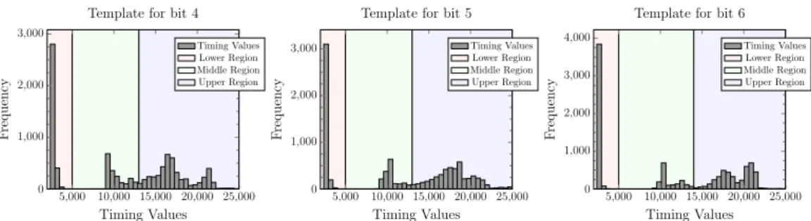
5,000 10,000 15,000 20,000 25,000 0
1,000 2,000 3,000
Timing Values
Frequency
Template for bit 4
Timing Values Lower Region Middle Region Upper Region
5,000 10,000 15,000 20,000 25,000 0
1,000 2,000 3,000
Timing Values
Frequency
Template for bit 5
Timing Values Lower Region Middle Region Upper Region
5,000 10,000 15,000 20,000 25,000 0
1,000 2,000 3,000 4,000
Timing Values
Frequency
Template for bit 6
Timing Values Lower Region Middle Region Upper Region