Research Collection
Doctoral Thesis
Interfacial Tuning of the Magnetoresistance and Magnetic Coupling in Metal/Oxide Thin Films
Author(s):
Phuong Dao, Trong Publication Date:
2021
Permanent Link:
https://doi.org/10.3929/ethz-b-000476182
Rights / License:
In Copyright - Non-Commercial Use Permitted
This page was generated automatically upon download from the ETH Zurich Research Collection. For more information please consult the Terms of use.
DISS. ETH NO. 27366
Interfacial tuning of the magnetoresistance and magnetic coupling in metal /
oxide thin films
A thesis submitted to attain the degree of DOCTOR OF SCIENCES of ETH ZURICH
(Dr. sc. ETH Zurich)
presented by Trong Phuong Dao MSc ETH, ETH Zürich
born June 17, 1989, citizen of Switzerland
Accepted on the recommendation of Prof. Dr. Pietro Gambardella Dr. Amalio Fernández-Pacheco
Prof. Dr. Manfred Fiebig
2021
Acknowledgements
This work would not have been possible without the help and support of the many people I met and worked with on the journey to finishing this thesis. First of all, I want thank Pietro Gambardella for giving me the chance to do this work in the first place, and Laura Heyderman, the close collaboration with whom ended up in three successful publications. Speaking of collaborators, I thank Zhaochu Luo and Aleš Hrabec for pushing the work we did on the lateral chiral coupling past what I ever could have imagined. The input of our co-authors was invaluable for the realization work. So I thank Marvin Müller for setting up the MOKE microscope, Manuel Baumgartner for supplementing our micromagnetic simulations with his own, and every other listed author for their help on beamtimes and more. As for the work on the epitaxial samples, Santos F. Alvarado must be lauded for his eternal patience in growing the many samples it took to ensure reproducibility.
I also want to express gratitude to the people that supported me
outside of this work, as it is them that pushed me to try, continue,
enjoy and finish this work. Among the first people to do so were
Can and Kevin, who taught me the naive joy of science, which
motivated me to start my doctoral studies. I could not have
been any luckier, having Manuel, Johannes, Christoph around
throughout my PhD to actually enjoy scientific discussions, as
well as to plan botanic endeavors. The constant glue that kept
the group together, while students and post-docs were rotated
in and out, were Rina and Santos with whom I was always able
in science there could be. Ania, Nick, Susmita and Claire made every moment in the secluded place that is the PSI the best time one could imagine, making me eagerly await the next day at work and after work.
While the I had an invigorated start to my PhD, the second half of my studies was marred by failures and an onset of depression.
In this phase, my family unconditionally provided me with a solid bedrock, giving me enough of a foothold to continue my work. Finally, I thank my partner Claire who has gone above and beyond anything a person in that situation could wish for. Without her presence and support, both emotionally and financially, the pressure to publish before defending and my unemployment would have made me quit without a doubt.
In the end, I count myself lucky, as I was able to work along side some of the most talented and meet some of the most incredible people, who were willing to build a support structure that carried me through my PhD.
For that I thank you all.
Declaration of Originality
I hereby declare that the following submitted thesis is original work which I alone have authored and which is written in my own words.
Title: Interfacial tuning of the magnetoresis- tance and magnetic coupling in metal
/oxide thin films
Author: Dao, Trong Phuong
Supervisor: Prof. Dr. Pietro Gambardella
With my signature I declare that I have been informed regarding normal academic citation rules and that I have read and understood the information on “Citation eti- quette”. The citation conventions usual to the discipline in question here have been respected.
Furthermore, I declare that I have truthfully documented all methods, data, and operational procedures and not manipulated any data. All persons who have substantially supported me in my work are identified in the acknowl- edgements.
The above work may be tested electronically for plagiarism.
Zürich, January 1, 2021
List of Abbreviations
Explanation
AHE Anomalous Hall effect
AHMR Anomalous Hall magnetoresistance AMR Anisotropic magnetoresistance ANE Anomalous Nernst effect CMR Crystalline magnetoresistance DMI Dzyaloshinskii-Moriya interaction
DW Domain wall
FM Ferromagnet
IP In-plane
ISHE Inverse spin Hall effect
HM Heavy metal
MR Magnetoresistance MTP Magnetothermopower OOP Out-of-plane
PHE Planar Hall effect
PMA Perpendicular magnetic anisotropy PNE Planar Nernst effect
RKKY Ruderman–Kittel–Kasuya–Yosida SAHE Spin anomalous Hall effect SHE Spin Hall effect
SMR Spin Hall magnetoresistance SOT Spin-orbit torques
UMR Unidirectional magnetoresistance
Abstract
We live in a society defined by constant growth. This is exempli- fied by information technologies which, over a time period of only a few decades, have transformed our way of life. This rapid expansion has relied heavily on there being ”plenty of room at the bottom”. However, as we are faced with the physical limitations of continuous miniaturization, there is a need for a new paradigm to support the growing computing power requirements of our society.
The field of spintronics provides us with several opportunities to increase the functionality of electronic devices in a sustainable way. After the discovery of the giant magnetoresistance and the tunneling magnetoresistance, which have revolutionized data storage technologies, scientists have continued to unravel novel effects and propose new applications that exploit the interplay of charge and spin degrees of freedom in electronic devices. In the last decade, a growing number of ways to measure and manipulate the magnetic state, which is used to store data, have arisen. One common thread in modern spintronics is the importance of interfaces.
In this thesis, we deal with a specific type of interface, that is
both well-known, and often overlooked: ferromagnet/oxide in-
terfaces. Specifically, we explore two main areas: firstly, magneto-
transport and current-induced SOTs, and secondly, the tuning
of magnetic anisotropies to induce chiral effects. To investigate
the resulting physical phenomena, both parts of this work have
involved the development of new fabrication techniques as well
as data acquisition and analysis methodologies.
To investigate the magnetotransport of ferromagnet/oxide interfaces, we study model systems consisting of Fe/oxide hetero- structures epitaxially grown on MgO(001). Our investigation reveals that current-induced effects that are typical of heavy metal/ ferromagnet bilayers, such as spin-orbit torques and unidirectional magnetoresistance, also exist in Fe
/oxide systems.
In addition, the crystallinity of the Fe is imprinted onto these effects, resulting in a dependence on the orientation of the current relative to the crystal lattice. Our results show that charge-spin conversion effects do not require the presence of heavy metals as the source of spin currents. Moreover, they show that subtle differences in the morphology and chemical composition of the interfaces can produce sizable changes of the spin-orbit torques and unidirectional magnetoresistance.
Besides playing a role in the magnetotransport properties, oxide interfaces can also influence the magnetic anisotropy of ferromagnets. In this thesis, we exploit the interface-mediated anisotropy in Pt/Co/AlO
xto induce what we coined ”lateral chiral coupling”. This coupling requires nanoscale control over the mag- netic anisotropy as it makes use of the Dzyaloshinskii–Moriya interaction, which has a very short range. For this purpose, we combined state-of-the-art fabrication techniques to develop a new process, which opened the door to the fabrication of laterally coupled in-plane and out-of-plane magnetized regions of the same layer. The effect of the lateral chiral coupling is manifold, leading to the exchange bias of adjacent in-plane and out-of-plane magnetized regions and the antiferromagnetic coupling of out- of-plane nanomagnets mediated by an in-plane spacer region.
Moreover, the lateral coupling enables field-free magnetization switching using spin-orbit torques, as well as domain nucleation sites with reconfigurable energy barriers.
The results of this thesis highlight the potential of ferromag-
net
/oxide interfaces to tune the magnetic ground state of single-
layer ferromagnets as well as their magnetotransport properties
and current-induced spin-orbit torques.
Zusammenfassung
Wir leben in einer Gesellschaft, die von ständigem Wachstum ge- prägt ist. Dies wird durch Informationstechnologien veranschau- licht, die, über einen Zeitraum von nur wenigen Jahrzehnten, unsere Lebensweise verändert haben. Diese rasche Expansion hat sich stark darauf verlassen, dass höhere Speicherdichten rein durch das Schrumpfen von Komponenten erreicht werden kann. Da wir jedoch mit den physischen Einschränkungen einer kontinuierlichen Miniaturisierung konfrontiert sind, ist ein neues Paradigma erforderlich, um den wachsenden Rechenleistungs- bedarf unserer Gesellschaft zu decken.
Das Gebiet der Spintronik bietet uns mehrere Möglichkeiten, die Funktionalität elektronischer Geräte nachhaltig zu verbessern.
Nach der Entdeckung des Riesenmagnetowiderstands und des Magnetischen Tunnelwiderstands, die die Datenspeichertech- nologien revolutioniert haben, haben Wissenschaftler weiterhin neue Effekte aufgedeckt und neue Anwendungen vorgeschlagen, die das Zusammenspiel von Ladungs- und Spin-Freiheitsgraden in elektronischen Geräten ausnutzen. In den letzten zehn Jahren wurde eine wachsende Anzahl von Möglichkeiten zur Messung und Manipulation des magnetischen Zustands gefunden, die zum Speichern von Daten verwendet werden können. Ein roter Faden in der modernen Spintronik ist der Fokus auf Grenzflä- chen.
In dieser Arbeit beschäftigen wir uns mit einer bestimmten Grenzfläche, die sehr bekannt ist aber auch oft übersehen wird:
Ferromagnet
/Oxid-Grenzflächen. Insbesondere untersuchen wir
zwei E
ffekte: erstens Magneto-transport- und strominduzierte Spin-Bahn-Drehmomente und zweitens die Mischung magneti- scher Anisotropien, um chirale Effekte zu induzieren.
Um die resultierenden physikalischen Phänomene zu untersu- chen, umfassten beide Teile dieser Arbeit die Entwicklung neuer Herstellungstechniken sowie Methoden zur Datenerfassung und -analyse. Um den Magnetotransport von Ferromagnet
/Oxid-
Grenzflächen zu testen, untersuchen wir Modellsysteme, die aus epitaktischen MgO(001)/Fe/Oxid-Heterostrukturen beste- hen. Unsere Untersuchung zeigt, dass strominduzierte E
ffekte wie Spin-Bahn-Drehmomente und unidirektionaler Magneto- widerstand, die in Schwermetall/Ferromagnet-Doppelschichten typisch sind, auch in Fe/Oxid-Systemen vorhanden sind. Zusätz- lich wird diesen Effekten die Kristallinität des Fe eingeprägt, was zu einer Abhängigkeit von der Richtung des Stroms relativ zur Kristallstruktur führt. Unsere Ergebnisse zeigen, dass Ladung- Spin-Umwandlungseffekte nicht Schwermetalle als Quelle für Spinströme erfordern. Darüber hinaus zeigen sie, dass subtile Unterschiede in der Morphologie und chemischen Zusammenset- zung der Grenzflächen beträchtliche Änderungen der Spin-Bahn- Drehmomente und des unidirektionalen Magnetowiderstands hervorrufen können.
Oxidgrenzflächen spielen nicht nur eine Rolle bei den Magne-
totransporteigenschaften, sondern können auch die magnetische
Anisotropie von Ferromagneten beeinflussen. In dieser Arbeit
nutzen wir die Grenzflächenanisotropie in Pt/Co/AlO
x, um die
laterale chirale Kopplung zu induzieren. Diese Kopplung erfor-
dert eine lokale Kontrolle der magnetischen Anisotropie, da die
Dzyaloshinskii-Moriya-Interaktion genutzt wird, die eine sehr
kurze Reichweite hat. Zu diesem Zweck haben wir modernste
Herstellungstechniken kombiniert, um ein neues Verfahren zu
entwickeln das die Herstellung von seitlich gekoppelten ma-
gnete ermöglicht. Der Effekt der lateralen chiralen Kopplung
ist vielfältig und führt zu einem Exchange Bias benachbarter Magneten und zur antiferromagnetischen Kopplung von anein- ander gereihten Nanomagneten. Darüber hinaus ermöglicht die laterale Kopplung ein feldfreies Umschalten der Magnetisierung mit Spin-Bahn-Drehmomenten.
Die Ergebnisse dieser Arbeit zeigen das Potenzial von Ferro-
magnet
/Oxid-Grenzflächen für statische und dynamische Ap-
plikationen.
Contents
Acknowledgements
3Abstract
9Zusammenfassung
131. Introduction
211.1. Motivation . . . 21
1.2. Background and Context . . . 23
1.3. Chapter Overview . . . 30
2. Magnetic interactions
332.1. Fundamental Interactions . . . 33
2.1.1. Exchange Interaction . . . 33
2.1.2. Dzyaloshinskii-Moriya Interaction . . . 35
2.1.3. Magnetostatic Energy . . . 36
2.2. Magnetic Anisotropy . . . 37
2.2.1. Shape anisotropy . . . 38
2.2.2. Magnetocrystalline Anisotropy . . . 39
2.2.3. Interface Anisotropy . . . 40
2.3. Magnetic Domains and Domain Walls . . . 40
2.4. External Influences . . . 42
2.4.1. Zeeman Energy . . . 42
2.4.2. Spin-orbit Torques . . . 43
2.5. Magnetization Dynamics . . . 44
3. Magnetotransport
473.1. Magnetoresistance . . . 47
3.1.1. Anisotropic Magnetoresistance . . . 48
3.1.2. Planar Hall E
ffect . . . 49
3.1.3. Anomalous Hall Effect . . . 50
3.2. Crystalline Magnetoresistance . . . 50
3.3. Interfacial Crystalline Magnetoresistance . . . 52
3.4. Current-induced Effects . . . 53
3.4.1. Thermoelectric Effects . . . 53
3.4.2. Origin of Spin Currents . . . 54
3.4.3. Spin-current-induced Effects . . . 59
4. Measurement Technique & Data Analysis
674.1. Hall Bar Geometry . . . 67
4.2. Harmonic Voltage Analysis . . . 70
4.2.1. First Harmonic Resistance Analysis . . . . 72
4.2.2. Second Harmonic Resistance . . . 80
4.3. Macrospin Simulations . . . 83
4.4. Data Analysis . . . 86
4.5. Magnetic Microscopy . . . 88
4.5.1. X-ray Photoemission Electron Microscopy 88 4.5.2. Magnetic Force Microscopy . . . 90
4.5.3. Wide-Field Magneto-optic Kerr Effect . . . 91
5. Sample Fabrication
935.1. Fabrication Methods . . . 93
5.1.1. Film growth . . . 93
5.1.2. Electron Beam Lithography . . . 95
6. Magnetotransport in Epitaxial Fe Single Layers
1036.1. Magnetoresistance and Current-induced Effects . 104
6.2. Sample Fabrication . . . 107
Contents
6.3. Magnetoresistance Measurements . . . 110
6.3.1. Magnetization Dependence of the Magne- toresistance . . . 110
6.3.2.
α-dependence of the CMR . . . 112
6.4. Current-induced Effects . . . 114
6.4.1. Spin-orbit Torques . . . 114
6.4.2. Unidirectional Magnetoresistance . . . 117
6.5. Discussion . . . 119
6.6. Conclusions . . . 126
7. Chiral Coupling: From Nanomagnets to Domain Wall Conduits
1297.1. Chiral Coupling in Nanomagnets . . . 130
7.1.1. In-plane/Out-of-plane Nanomagnets . . . . 131
7.1.2. Lateral Exchange Bias . . . 133
7.1.3. Lateral Antiferromagnetic Coupling . . . . 134
7.1.4. Current-induced Switching . . . 138
7.1.5. Size Limitations of the Chiral Coupling . . 138
7.2. Chiral Domain Wall Injectors . . . 140
7.2.1. Structure of Chiral Domain Wall Injectors . 143 7.2.2. Magnetic Anisotropy Characterization . . 144
7.2.3. Asymmetric Domain Nucleation . . . 146
7.2.4. DMI-driven Domain Nucleation . . . 151
7.2.5. Driving Domain Wall Conduits . . . 153
7.3. Summary . . . 156
8. Summary and Outlook
159Curriculum Vitae
165Education . . . 165
Teaching experience . . . 165
Publications . . . 166
Conference Contributions . . . 167
A. Device Fabrication
169A.1. Fabrication of MgO(001)/Fe/Ox Hall bars . . . 169 A.2. Fabrication of Pt/Co/AlO
xdomain wall injectors . 177
Bibliography
1851. Introduction
1.1. Motivation
The information age has left its mark on society, with digital devices having found a purpose in every aspect of our lives. With an estimated 50 Billion devices connected to the internet, ranging from smart phones to the often ridiculed smart refrigerator, the all so frequently reported ”ubiquity of smart devices” is far from an exaggeration. By now we live in a permanently connected society, where each personal device requires a constant drip feed of information from the ”cloud” to function properly. The backbone of the infrastructure, which is able to serve our needs in a blink of an eye, are data centers, for which demand has rapidly grown.
To meet this demand, data centers have massively expanded
in the last ten years, increasing their storage capacity more than
25-fold, network traffic 10-fold and workload 5-fold [1]. There
are no signs of this expansion slowing down anytime soon, as
the push towards increasingly higher fidelity and on demand
entertainment is in full force. This problem was exacerbated in
this year’s COVID-19 pandemic, which has turned the average
office worker into amateur streamers, forcing them to send pixe-
lated videos of their backlit faces across the globe. In addition,
the emergence of artificial intelligence, which is on the cusp of
permeating every part of technology, is continuing our increas-
ingly computing-intensive status quo. History indicates that this
ever growing consumption is deep-rooted in our modern society,
ruling out restraint as a way forward, even in the face of a wilting planet.
Thanks to the concerted effort of engineers and scientists, however, the total energy usage of data centers has barely been affected by this expansion. Reductions in idle power, improved processor and storage efficiency and increased storage density have contributed to keep the increase of the total energy usage to a few percent [1], despite the massive increase in storage capacity, traffic and workload. To persevere in this constant battle, we need a breakthrough, as traditional data handling architectures, which have scaled incredibly well as advertised by Moore’s law, are expected to reach their limits soon.
However, instead of waiting with baited breath for a panacea, recent developments demonstrate how a move towards special- ized technologies that solve specific problems can lead to faster progress. A prime example is the tensor core, which can be thought of a stripped down computing core that has been op- timized to significantly speed up artificial intelligence network computations, but lacks the flexibility of a traditional core. Since its first implementation into Google’s data centers in 2015, it has made its way into enthusiast products a few years later and arrived in mainstream consumer products in 2020. The same principle, of developing solutions specific to the problem at hand, is pursued in quantum computers and neuromorphic computing, though these technologies have yet to reach maturity.
The development of new technologies is a never-ending en-
deavor, which requires strong interfacing between science and
technology. A field that has excelled in this respect is the field
of spintronics, which through the discovery of a vast assort-
ment of physical phenomena, involving the interaction of electric
charge and spin, has produced the building blocks of current
smart devices [2]. In this thesis, we aim to expand the existing
tool set used to conduct spintronic studies and develop future
1.2. Background andContext
technologies. For this we investigate the rich physics emerging from what might be considered the most underappreciated, yet very commonly occurring, component of the spintronic devices, namely ferromagnet (FM)
/oxide interfaces. But before we can properly highlight the role of these interfaces and in which direc- tion we can take them, we will first set the stage by covering the achievements that have led us here.
1.2. Background and Context
The poster child of spintronics is the giant magnetoresistance (GMR) , which introduces an electrical resistance in multilayer thin films depending on the relative orientation of two or more ferromagnetic layers that are separated by non magnetic metal layers [3, 4]. While magnetoresistive effects were not novel at the time of the discovery of the GMR [5, 6], what set it apart was the strength of its effect, causing resistance changes that were orders of magnitude larger than the other magnetoresistance (MR) effects at the time. The fact that the GMR causes large signals for small changes in the magnetization, quickly led to its implementation into magnetic hard disk drives, where it was used in the read head to sense the magnetic areas, i.e. bits, of the hard disk, which encode the stored information. The high sensitivity of the GMR allowed for the miniaturization of hard disk drive components down to the nano-scale, and subsequently led to an unprecedented increase in storage density.
Remarkable is, how fast this development happened, starting with the experimental discovery of the GMR in parallel by Grünberg and Fert [3, 4], followed by first commercial products a decade later and culminating with the Nobel prize in 2007.
Not only was the Nobel prize awarded for the technological
impact the GMR had but also for it being the first real application
of nanotechnology, as the GMR can only be observed in multilayer thin films. Thus, the implementation of the GMR into HDDs hinged on thin film fabrication techniques, which were only developed slightly over a decade before the discovery of the GMR , and includes several other phenomena exclusive to thin films, some of which we will discuss later on. The feature that lets thin film multilayers stand out, is the high interface to volume ratio, which amplifies interface-induced effects. These effects, some of which rely on the intrinsic broken inversion symmetry at the interface, often decay over a short distance, making them only observable at the nanoscale.
One of the earlier discovered interface effects was the perpen-
dicular magnetic anisotropy (PMA) in Pd/Co multilayers [7],
which aligns the magnetization of the FM to be perpendicular to
the film plane, instead of parallel to the film, which is normally
the case. PMA, in addition to the GMR, was essential in driving
up the storage density of HDDs, as it offered a solution to a
problem that plagued the miniaturization of magnetic storage
until then. When magnetic bits are made smaller, the average
lifetime of the stored information is reduced, since the energy to
flip the bit decreases. To compensate for this, we would need to
increase this energy through other means, which the PMA makes
possible, as the strength of the induced uniaxial anisotropy is
potentially very large. This potential was confirmed as time
went on, as more heavy metal (HM)/FM combinations were
found to exhibit PMA with increasing strength. While HM/FM
interfaces undoubtedly induce strong PMA, owing to the strong
spin orbit coupling of the HM, spin orbit coupling was soon
found not to be the only mechanism behind PMA. Particularly,
PMA was frequently observed in FM/oxide interfaces such as in
the CoFe/AlO
xinterface [8]. In this specific system, a study in the
early 2000s showed that the strength of the PMA is determined
by the oxidation level of the interface, transitioning from in-plane
1.2. Background andContext
magnetization for underoxized interfaces, to a peak PMA for a perfectly oxidized CoFe/AlO
xinterface and subsequent degrada- tion for overoxidized interfaces. Consequently, the origin of the PMA in FM
/oxide cases was traced back to orbital hybridization, which is very sensitive to the oxygen level at the interface.
Not only can we induce anisotropies into single FM lay- ers, in thin film multilayers, it is also possible to couple sep- arate magnetic layers to each other using the so-called Ru- derman–Kittel–Kasuya–Yosida (RKKY) coupling. The RKKY coupling is observed in structures where FM layers are sepa- rated by thin conducting non-magnetic metals, which causes the magnetization of the separated FM layers to align either ferro- magnetically (parallel) or antiferromagnetically (anti-parallel).
Whether ferromagnetic or antiferromagnetic coupling prevails for a specific separation layer, depends entirely on the thickness of the separation layer and can change within a few atomic monolayers.
Another phenomenon often used in conjunction with the RKKY coupling, in order fix the orientation of one of the FM layers, is the exchange bias emerging at FM/antiferromagnet interfaces. Here, the surface magnetization of the antiferromagnet, which for all practical purposes can be considered fixed in one direction, cou- ples to the magnetization of the FM. This causes the FM to favor one specific direction and if overlapped with a uniaxial magnetic anisotropy, stiffens the magnetization to the point where, in the absence of external magnetic fields, the magnetization will automatically revert to that preferred orientation.
These examples were brought up to highlight the variety of
phenomena that emerge exclusively in thin film structures, but at
the same time, this reveals the limitations of these effects in that
they only occur in thin film multilayers. This is the entry point of
Chapter 7 of this thesis, where we aim to combine the control over
the PMA in HM/FM/oxide structures with an interfacial effect,
namely the Dzyaloshinskii-Moriya interaction (DMI), to develop a technique to strongly couple laterally arranged nanomagnets.
The aforementioned DMI [9, 10] is an effect that occurs in structures that lack inversion symmetry, which in our systems is the case at the interface. The DMI is a local interaction be- tween magnetic moments similar to the exchange coupling. The exchange coupling forces neighboring magnetic moments to be parallel or anti-parallel, giving rise to ferromagnetism and antiferromagnetism in the first place. The DMI on the other hand, promotes orthogonal arrangement of magnetic moments, resulting in spin spirals [11] and other non-trivial spin structures [12, 13]. Furthermore, the DMI imposes a handedness or chirality on the system. In systems with PMA, this chirality manifests largely in domain walls, which are the transitional regions be- tween anti-parallel aligned regions with uniform magnetization, causing the magnetization in all domain walls to rotate with the same handedness [11, 14–16]. More specifically, the domain walls always chiral Néel wall configurations, which one, depends on the sign of the DMI. Effectively, this couples the in-plane (IP) component of a magnetic moment to the out-of-plane (OOP) component of its neighbors.
Here, we investigate coupled IP-OOP magnetized nanomag-
nets, in which the magnetization mimics the chiral Néel wall
configuration that naturally occurs in DWs. For the fabrication of
these devices, we leverage the nano-resolution of electron beam
lithography to pattern the nanomagnet and selectively oxidize
Pt/Co/AlO
xstructures. The selective oxidation allow us to in-
duce the PMA only in the desired regions while maintaining IP
magnetization in the rest of the device. Using these nanomagnets
we demonstrate, that the DMI can be used to achieve lateral and
antiferromagnetic coupling of magnetic regions. With the lateral
coupling, it is possible to generate large and complex networks
of coupled magnetic regions, which has the potential to be used
1.2. Background andContext
in logic and non-Boolean devices [17, 18].
While the chiral coupling has a tremendous influence on the static behavior of the magnetization, its true value lies in the impact it has on the DW dynamics when combined with spin-orbit torques (SOTs), which is the focus of the second half of Chapter 7. The initial discovery of SOTs, in which unusually fast domain wall propagation induced by electrical currents was demonstrated [19], launched some of the most exciting investigations in the recent years in spintronics [20].
The massive body of work that has been generated since then has unravelled many mysteries surrounding SOTs, resulting in a deep understanding of the domain nucleation and domain wall propagation using SOTs [21, 22]. One of the revelations was that SOTs allow for ultra-fast switching of magnetic nano- islands. This is largely owing to very high DW velocities and the possibility of eliminating the incubation time, which otherwise would delay the nucleation processs [23, 24]. The high DW velocities make SOTs especially suitable to drive domain wall conduits or racetracks, a technology that, if realized to its full potential, promises a massive boost to our data storage capacity.
Nevertheless, SOTs come with their own set of issues. One is the requirement of an external field parallel/anti-parallel to the injected current to deterministically switch the magnetization [21].
For the DW propagation, this field must either be maintained to prevent unwanted nucleation, or the current must be decreased, which prevents further nucleation but also decreases the DW velocity.
Here, we propose an alternative nucleation scheme, namely
the use of lateral IP-OOP boundaries as chiral domain injectors
[25]. At these boundaries, the chiral coupling stabilizes DMI-
favored magnetization configurations, prohibiting the nucleation
of new domains. Configurations unfavored by the DMI, on the
other hand, are metastable, and domain nucleation using SOTs
is facilitated. Thus, in these chiral injectors the nucleation can be controlled by the magnetization direction of the IP region alone.
Furthermore, once a domain was nucleated from a metastable state, it automatically reverts to a stable one, preventing any additional unwanted domain nucleation. The whole nucleation and propagation process can be done without external magnetic fields, using a stream of unipolar current pulses with constant amplitude. However we do not get rid of external fields com- pletely, as the nucleation still has to be primed by flipping the IP region, for which we use external fields, though we do propose all electrical chiral injector designs.
A significant portion of SOT studies were conducted on HM/FM bilayers, which have proven to be an excellent model system, owing to the large spin Hall effect (SHE) associated with HMs [26]. The SHE is capable of converting an electrical current into a spin current, which subsequently affects the FM resulting in SOTs. The study of SOTs in HM/FM bilayers did not only reveal the inner workings of the SHE and the SOTs.
The development of SOT characterization techniques inevitably advanced measurements capabilities and our understanding of the interplay between electrical, spin and heat currents, which shapes the transport properties of thin films. These advances are built on a thriving subset of MR studies, which have led to the discovery of a vast array of new MR effects.
The foundation of the MR in these bilayers are the famed anisotropic magnetoresistance (AMR) [5] and the anomalous Hall effect (AHE) [6], which are intrinsic to FMs. However, in these thin film bilayers the MR often deviates from the traditional models. Many of the additional contributions were traced back to the generation of different fluxes, i.e. heat and spin, by the electric current, which subsequently produce their own electric signal.
Among the additional MR contributions are the unidirectional
MR (UMR) [27] and the the spin Hall MR (SMR) [28], which have
1.2. Background andContext
typically been attributed to the spin current generated by the SHE.
Although the SMR was first demonstrated in HM/insulating FM bilayers, based on a mechanism that is tied to the fact that the FM does not conduct, other effects resembling the SMR emerged soon thereafter. However, before long, other possible mechanisms were brought into the picture, such as magnetic proximity effects in HMs, which can generate a MR in the HM itself [29], and the anisotropic interface MR [30]. As studies went on to include a more diverse set of systems, SMR-like signals were also found in systems with no HMs [31–33], therefore lacking the obvious provider of the SHE, which is essential to the manifestation of the SMR. Thus, for single layer FM thin films several new mechanisms were proposed, one of which is based on the AHE in structures with high aspect ratio [34]. For thicker textured layers, the geometrical size effect was suggested to be the source of the SMR-like magnetization dependence [35].
Finally, a recent investigation [36] went back to one of the original MR studies [37] and found that in partially crystalline materials, the presence of an SMR-like magnetization dependence of the MR is actually allowed by symmetry and thus could be much more common that previously thought.
This barrage of phenomena, which all describe the same man- ifestation of the MR from a different perspective, shows how difficult the determination of microscopic origin of these effects can be. This is not exclusive for the SMR-like signal, which we only used as an example, but applies to every MR and current- induced effect that was discovered in recent years. On top of that, the models used to explain one effect should also be relevant for the rest of the transport properties, complicating the process even further. Understanding the magnetization sensing capabilities that are available to us, is paramount to maximize their potential.
In the last part of this thesis, we aim to unify the library of MR and
current-induced e
ffects, which are relevant to magnetic thin films.
Building on prior MR studies, we investigate a large variety of transport properties of epitaxial MgO/Fe/oxide structures using a single measurement technique, with the goal of correlating cause and effect across all transport properties measured. For this, we develop a characterization methodology specifically for anisotropic systems, which allows for the consistent and precise quantification of the MR and current-induced effects.
1.3. Chapter Overview
The content of this this thesis has already been weaved into the previous section but to repeat, two main projects form the foun- dation of this thesis. One focuses on the lateral chiral coupling of IP-OOP boundaries and in the other we investigate the transport properties of epitaxial single layer iron. The underlying funda- mental physics and characterization methods applied in the two projects have a lot of overlap. Thus this thesis is structured to front load these commonalities, which are then adapted to the specific cases in the project Chapters.
In Chapter 2, we lay the groundwork of the fundamental magnetic interactions, which play a role in our thin films. This encompasses the direct interaction between magnetic moments, magnetic anisotropies and the various methods to manipulate the magnetization.
Chapter 3 introduces the magnetotransport phenomena stud-
ied in this work, which manifest through the interaction between
external magnetic fields, magnetization of solids, electric cur-
rents and other fluxes. Specifically, we describe the traditional
MR model, which includes the AMR and AHE. This model is
then adapted for crystalline ferromagnetic thin films. In addi-
tion to the MR, we also discuss the origin of current-induced
1.3. ChapterOverview
e
ffects, such as the thermo-electric e
ffects and spin current related phenomena.
In Chapter 4, we dive into the measurements and analysis techniques that were developed for this work. We start with the description of the harmonic voltage analysis, which forms the backbone of the transport measurements, followed by the specific manifestations of the transport phenomena in this measurement technique, listed in the previous chapter. To quantify these phenomena in systems with magnetocrystalline anisotropy, I developed an iterative fit procedure that requires no assumptions or input other than the independent and dependent variables from the measurement itself, which is covered in its entirety in this chapter.
Chapter 5 contains a detailed description of the growth and pattering of the FM/Ox systems studied in this work, which entails the deposition methods, techniques to control the oxidation and lithography procedures. In addition to a description of the fabrication techniques used, we provide general considerations that need to be taken into account to optimize the device quality.
In Chapter 6, we report on our investigation of the MR and current-induced effects in epitaxial MgO(001)/Fe/oxide structures.
As mentioned above, we measure and separate the abundance of magnetotransport phenomena in a singular study using a single measurement technique designed to map the angular dependence of crystalline magnetotransport effects. In this way, we obtain insight into the complex physics of crystalline magnetotransport devices, opening the door to the future harnessing of these rich materials.
In Chapter 7, we present the work, consisting of two projects, that led to the discovery of the lateral chiral coupling [25] and we propose functional designs based on this new phenomenon [25].
The first half covers the chiral coupling as it was discovered in
IP-OOP nanomagnets. We show that the magnetization of the IP
and OOP regions are strongly coupled to each other through the DMI, for which we provide proof using imaging techniques and transport measurements. The complexity and size of chirally coupled structures is also shown to be scalable as the coupling can propagate changes in the magnetization over multiple IP- OOP boundaries. Due to the local nature of the chiral coupling, the boundary density must be kept high though for the chiral coupling to fully determine the magnetic configuration.
From a magnetization dynamics point of view, the IP-OOP boundary can be considered as a configurable nucleation site.
This is demonstrated in the second half of the chapter, where we explore the usage of IP-OOP in domain wall conduits as injectors.
Using SOTs, we show that the domain nucleation probability strongly depends on the chirality of the magnetic configuration at the IP-OOP boundary. By exploiting this property we devise a switching protocol with which any arbitrary sequence of domains with alternating magnetization can be injected into domain wall conduits, using a stream of unipolar current pulses with constant amplitude.
Finally, in Chapter 8, we summarize the achievements of this
thesis and give an outlook of interesting directions to follow in
coming years.
2. Magnetic interactions
The study of the magnetoresistance, current-induced effects, and magnetization dynamics in thin film heterostructures, which form the goal of this work, is underpinned by the fundamental understanding of the interactions that govern the behavior of the magnetization of a ferromagnet. This chapter contains a general introduction to the relevant interactions, some of which are intrinsic to magnetic materials and some that we have control over. For the specific implementation of these interactions into macrospin simulations we refer to Chapter 4.
2.1. Fundamental Interactions
2.1.1. Exchange Interaction
The first question we need to answer when talking about mag-
nets is what is the interaction that enables a collection of atomic
magnetic moments, to spontaneously align and form a net mag-
netization
M =M
smand give rise to ferromagnetism, instead
of randomly pointing in all directions. The answer is the direct
interaction between individual magnetic moments, specifically
the exchange interaction. The exchange interaction is a quantum
mechanical effect thar originates from the exchange symmetry
of indistinguishable particles, in this case electrons. Thus, it is a
short-ranged interaction, governing only the interaction between
Ferromagnetic
Js> 0
Antiferromagnetic Ferrimagnetic
Js< 0
Figure 2.1.: The exchange interaction forces the magnetic mo- ments to align with each other giving rise to ferro- magnetism or antiferromagnetism/ferrimagnetism.
The sign of the exchange constant A
excdetermines whether parallel or anti-parallel alignment is pre- ferred. For positive values of A
excall moments align in the same direction, resulting in a ferromagnet. For negative values of A
excthe moments alternate result- ing in an antiferromagnet if all moments are equal, or ferrimagnet if the two sublattices, one with the moments pointing up and the other with moments pointing down, do not have the same magnetization.
neighboring spins
S, leading to an energy term [38]E
exc =−2A
exca
X
i,j
Si·Sj
,
(2.1)
where A
excis the exchange stiffness constant and a is the lattice constant of the FM. As can be seen from this expression, the exchange interaction describes the parallel (A
exc >0) or anti- parallel (A
exc<0) alignment of neighboring spins, which leads to either ferromagnetism or antiferromagnetism, respectively.
For Co and Fe thin films the exchange stiffness constant depends on the thickness and the interfaces leading to values ranging from 5–30 pJ m
−1[39].
In the absence of the exchange interaction, we observe para-
2.1. FundamentalInteractions
d > 0 d < 0
Figure 2.2.: The DMI forces perpendicular alignment of neighbor- ing spins, which is in competition with the exchange interaction. The result of strong DMI are spiraling magnetic microstructures as shown, where the rota- tional sense, or chirality, of these structures depends on the sign.
magnetism and diamagnetism, where the magnetic moments can be aligned with an external magnetic field but do not align spontaneously.
2.1.2. Dzyaloshinskii-Moriya Interaction
Like the exchange interaction, the DMI describes the coupling between neighboring spins, with the difference that the DMI promotes perpendicular alignment of spins. The DMI was first observed in antiferromagnetic
α-Fe2O
3, where it induced weak ferromagnetism [40]. Although the original groundwork was layed decades ago, a working theory that is able to predict both the sign and strength of the DMI in HM/FM bilayer thin films, was only developed recently [41]. There, two factors were found to impact the DMI. The first is the orbital HM-FM hybridization, which increases the more the electron bands overlap at the interface, and consequently increases the strength of the DMI.
The sign of the DMI depend on the spin-orbit coupling, which
results in spin mixing-orbital transitions at the interface. In
other words, the spin-orbit coupling only allows for specific spin
transitions from a d-orbital in the FM to a d-orbital in the HM and
these transition cause the spin to rotate slightly with a chirality set by the spin-orbit coupling. The rotated spin interact with the magnetization in the FM as they transition back, causing the magnetization to rotate in a chiral manner as well.
The effect of the DMI on the magnetic moments is highlighted in the energy contribution
E
dmi =−Xi,j
d uij
·
Si×Sj
(2.2) where d is the DMI vector that defines the strength and rotational sense or chirality of the DMI. d is determined by the vector
uijthat connects the location of
Sito the location of
Sj. This expression shows that the DMI by itself will promote the formation of magnetic spirals, where the magnetization rotates around
das we travel along
uij[42]. For the Pt/Co/AlO
xbilayers studied here d
≈ −1 mJm
−2[17, 43], resulting in what is referred to as left-handed chiral spin structures.
2.1.3. Magnetostatic Energy
In addition to these short range but strong interactions, mag- netic moments also interact on a longer range, though more weakly, through the magnetostatic energy[38]. This energy can be thought of as the cost involved in maintaining a magnetic field generated by the magnetization outside of the body of the magnet. Minimizing this field entails the reduction of the density of surface pole charges
M ·n, where nis the surface normal.
This can be achieved either by pairing opposite surface pole
charges, resulting in an altered magnetization configuration, or
by aligning the magnetization parallel to as much of the surface
as possible.
2.2. MagneticAnisotropy
+ + +
+
- - - -
+ +
+ +
- + -
- -
-
Figure 2.3.: The magnetostatic energy describes the the cost of maintaining magnetic fields outside of the magnet, which scales with the density of surface pole charges.
These so-called magnetic charges are generated by the surface magnetization itself when aligned per- pendicular to the surface. The magnetostatic energy can be minimized by pairing opposite charges or by aligning the magnetization parallel to the surface.
2.2. Magnetic Anisotropy
For now we have mostly addressed how magnetic moments align relative to each other, however, a major factor in determining the direction of the magnetization
mis the magnetic anisotropy.
As the name implies, here, the symmetry of magnets, or in our
case more specifically magnetic thin films, changes the energy
associated with certain magnetization directions, resulting in
preferred axes to align with, also called easy axes, or axes to avoid,
called the hard axes. Magnetic anisotropies can be caused by a
variety of factors and in any given magnetic system a number
of these anisotropy axes may exist and overlap, generating a
complex energy landscape for the magnetization. Here, we will
discuss the sources of the anisotropies in the epitaxial Fe system and the Pt/Co/AlO
xsystem studied in Chapter 6 and Chapter 7, respectively, starting with the shape anisotropy.
2.2.1. Shape anisotropy
Shape anisotropy is one of the consequences of trying to minimize the magnetostatic energy. If we treat the magnetization as a single uniform vector that cannot minimize the magnetostatic energy by breaking into domains, the remaining option to lower the energy is to minimize the surface poles. As a result,
mwill typically prefer to align parallel to surfaces, and minimize the area with the magnetization pointing perpendicular to the surface. The energy associated with the shape anisotropy is given by[38].
E
dem/V= µ0M
s2
X
i=x,y,z
N
im
2i,(2.3) where
µ0is the vacuum permeability and
Niare the components of the demagnetizing factor, which depends on the shape of the magnet. For a system with only one elongated or constricted dimension the shape anisotropy introduces a uniaxial anisotropy, such that
E
uni/V=K
uni1
−(m
·u)2(2.4) where K
uniis a uniaxial anisotropy constant and
uis the direction of the axis that coincides with the longest dimension of the shape.
For flat shapes K
uniis negative, while for elongated shapes K
uniis positive. Notable examples of systems with significant shape anisotropy are magnetic thin films, in which it generates a hard axis perpendicular to the film, and magnetic micro-/nanowires, in which the high elongation creates an easy axis along the wire.
In these two examples the shape anisotropy exists by virtue of
the design of the overall shape of the system, however it can also
manifest more subtly as a result of textured roughness [44–47].
2.2. MagneticAnisotropy
2.2.2. Magnetocrystalline Anisotropy
Magnetocrystalline anisotropy arises from the interplay of the spin-orbit interaction and the energy splitting of the d-orbitals induced by the crystal field. This results in systems, where the anisotropy is tied to the crystal structure of the ferromagnet. An example of this are the epitaxial Fe layers studied in this work (see Chapter 6), where the cubic symmetry of the crystal produces a cubic magnetocrystalline anisotropy with three perpendicular easy axes. If we set the
<100>directions of the cubic crystals to correspond to
x,y, andz, the energy density for a cubic crystal is[38]
E
cub/V=K
1m
2xm
2y+m
2xm
2z+m
2ym
2z+
K
2m
2xm
2ym
2z(2.5) where K
1and K
2are anisotropy constants that dictate the direction of the easy axes. In the epitaxial MgO(001)/Fe systems studied here, the easy axes coincide with the three main axes of the crystal, which is described by a large value for K
1≈50 Jm
−3and a small one for K
2 ≈ ±5 Jm
−3[48]. As the magnetocrystalline anisotropy is so closely related to the crystal structure, straining the structure will change the anisotropy. This phenomenon is called magnetostriction, which in strained epitaxial Fe films can introduce a uniaxial anisotropy along the strain direction.
In polycrystalline systems, such as Pt/Co/AlO
xon which we
will focus in Chapter 7, the individual contributions to the
anisotropy of the randomly oriented crystal grains usually end up
cancelling each other and therefore suppress the manifestation of
an magnetocrystalline easy axis. If the orientations of the crystals
are not random and not evenly distributed, this can result in a
texture of the film, which can induce magnetic anisotropy even
in non-epitaxial films.
2.2.3. Interface Anisotropy
The magnetic anisotropy is not only determined by the crystalline structure of the ferromagnet and its shape, but also by the materials that the ferromagnet is in contact with. At the interface between the ferromagnet and its neighboring materials, orbital hybridization can be the source of strong magnetic anisotropies, which introduces a uniaxial anisotropy perpendicular to the interface
E
int/V=K
int1
−(m
·n)2.
(2.6)
where K
intis the interface-induced anisotropy term and
nis the normal of the interface. In the prominent case of Pt
/Co
/AlO
xthis anisotropy can be used to overcome the shape anisotropy of a thin film and induce a PMA [49]. Furthermore, as the interface anisotropy is induced by orbital hybridization, the Co
/AlO
xinter- face is a prime example of the impact the oxidation state can have on the interface anisotropy. Here, both slight underoxidation or overoxidation will greatly diminish the induced anisotropy, weakening it enough for the system not to exhibit a PMA.
2.3. Magnetic Domains and Domain Walls
As described above, the magnetic configuration and behavior are determined by a number of competing interactions, not all of which favour a single domain state. While the exchange interaction promotes the alignment of all magnetic moments, the DMI and magnetostatic interactions promote non-collinear alignment of magnetic moments. The combination of these competing interactions can lead to a multi-domain state, made up of different domains that individually consist of a uniform magnetization direction, but are not aligned with one another.
In the regions separating different domains, aptly named DWs,
2.3. MagneticDomains andDomainWalls
Néel walls:
Block walls:
Figure 2.4.: The structure of 180° DWs in thin films can be cat- egorized into two types. In Bloch walls the magne- tization rotates around the normal
nof the DW. In Néel walls the magnetization rotates around
m×n.In the presence of the DMI, chiral Néel walls prevail, which has been exploited with great success for DW propagation with SOTs.
the magnetization smoothly transitions from one domain to the other[38].
A lot of effort has been put into resolving the configuration of the magnetization inside the DWs, as their internal structure governs many dynamic properties of a magnet. Of special interest to our work presented in Chapter 7 are 180° DWs. In these cases, we can identify two types of DWs, namely Bloch walls where the magnetization rotates around the normal
nof the DW and Néel walls where it rotates around
m×nin either direction [50].
In thin films with PMA, Bloch walls are generally energetically
favored due to their lower magnetostatic energy. Constricting
the DW, for example in a nano wire, pushes the preference
towards Néel walls, since the rotation of
mtowards the axis
of the wire reduces the magnetostatic energy compared to the
Bloch configuration. The transition between the two DW types is
gradual as the wire becomes more narrow, leading to DWs with
hybrid structures that have characteristics of both Bloch and Néel walls [51]. While this mechanism plays a role in determining the DW type, it does not explain why in the Pt/Co/AlO
xsystem, we exclusively observe Néel walls [11, 14]. The main determining factor of the DW configuration in these systems is the DMI, which in addition to forcing Néel walls, also lifts the degeneracy of di
fferent rotation directions or chiralities [14, 15], which is a prerequisite for the deterministic manipulation of these DWs using electric currents [52].
2.4. External Influences
While the various interactions and anisotropies listed above are leading factors in determining the magnetization and its microstructure, as material parameters, they offer us little active control over the magnetization during a measurement. Here, we will cover what options are available to us to precisely manipulate the magnetization using external influences.
2.4.1. Zeeman Energy
We start with the interaction of
Mwith an external magnetic field
Hext, which is described by the potential energy [38]
E
zee =−M·Hext=−M
sH
extcos
θext(2.7) also known as the Zeeman energy. Here,
θextis angle spanned by
Mand
Hext. As stated in Eq. 2.7, the Zeeman energy is minimized when the magnetization and the external field are parallel and increases as the misalignment
θextincreases.
The external magnetic field
Hext, produced by an electromag-
net in our case, is not the only contribution to the Zeeman energy,
as the electric currents sent through our samples for the magneto-
transport measurements also generate an Oersted field. In the
2.4. ExternalInfluences
most well-known case - that of a cylindrical wire - the Oersted field circulates around the wire, with a magnitude of the field inversely proportional to the distance from the centre of the wire. For thin films, the Oersted field outside of the film can be approximated using an infinitely extended sheet model by
H
oe = µ0J
2
,(2.8)
where
µ0is the vacuum permeability, J
0is the current density. The resulting H
oeis a field parallel to the film plane and perpendicular to the current. Because H
oeis only generated outside of the layer, a uniform current flowing through the ferromagnet will not generate an Oersted field that affects the ferromagnet itself.
However, any current running through neighboring layers will generate an Oersted field, which will affect the ferromagnet.
2.4.2. Spin-orbit Torques
In addition to the Oersted field, the electrical current can exert a torque on the magnetization by producing a spin current, i.e.
a flow of electrons with aligned spins. The alignment of the spin results in a spin polarization
σthat can interact with the magnetization. This process naturally occurs in ferromagnets in a variety of ways and can be artificially enhanced by inversion symmetry breaking, such as through the interface engineering in heavy metal/ferromagnet bilayers [20, 53]. The mechanisms behind the spin polarization of electrical currents are covered in more detail in Section 3.4.2. SOTs then arise through the exchange interaction between the magnetization and the spin polarization.
The torques exerted by the spin polarization can be decomposed
into two components, in particular, the field-like (
∝m×σ) andthe damping-like SOT (
∝ m×(m
×σ)) [54]. The field-like anddamping-like SOTs have been named for their symmetry, which
mimic the precession and damping torque, respectively, of a magnetic field parallel to
σ. Nevertheless, they are not just twocomponents of a single field, but instead are more accurately described via the two e
ffective fields
Hfland
Hdlthat can scale independently. The direction of these effective fields are defined by
Hfl∝σ
(2.9)
resulting in a field-like torque
∝m×σand
Hdl∝m×σ
(2.10)
giving us the damping-like torque
∝m×(m
×σ). SOTs have beenused to great e
ffect for magnetization manipulation in HM
/FM systems, ranging from chiral DW propagation in magnetic wires to full magnetization reversal of magnetic dots and Hall bar structures [20].
2.5. Magnetization Dynamics
As was discussed in this chapter so far, a multitude of effects are acting on the magnetization at any time, each leaving its unique footprint on the energy landscape experienced by
M. Fora single magnetic moment, the manner with which
mnavigates through this landscape is governed by the Landau-Lifshitz- Gilbert equation [38]
∂m
∂
t
=− γ1
+α2 m×Heff− γα1
+α2 m×m×Heff
,
(2.11)
where
γ= 2µ~Bis the gyromagnetic ratio,
αis a phenomenological
damping parameter and
Heffis the effective field, containing
all the aforementioned e
ffects ranging from direct interactions,
anisotropies to external influences. The motion described by
2.5. MagnetizationDynamics
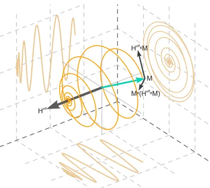
H ˣMeff
Mˣ(H ˣM)eff
M
Heff
Figure 2.5.: The interaction between the magnetization and an e
ffective field
Heffis governed by the LLG equa- tion. The LLG equation describes the trajectory of the magnetization as a combination of a precession
Heff×maround
Heffand a motion towards the field
m×
Heff×m