Ultrasonic Assessment of Permanent Joints of Powder Metallurgy Parts Obtained by Pulsed Electromagnetic Field
A. Tatarinov1, V. Mironov1, M. Kolbe2*
1 Laboratory of Powder Materials, Riga Technical University, Latvia
2 West Saxony University of Applied Science Zwickau, Germany
* Corresponding author. Email: Matthias.Kolbe@fh-zwickau.de
Abstract
Radial pressing by a pulsed electromagnetic field (PEMF) is a fast and effective way of rigid connection of thin-walled powder parts. The quality of joining depends on well-chosen intensity and uniformity of the applied PEMF. The difficulty of non-destructive tests of joints by standard ultrasonic flaw detectors is often caused by a curved shape and a small radius of parts. The coarse-grained structure and porosity of powder parts cause a strong attenuation of ultrasound at frequencies above 3 MHz. Two ultrasonic methods were compared for sensitivity to weak and tight connections of “bush-on-bush” and “bush-on-rod” joints – pulse-echo and time-of-flight (TOF). Bushes were made of powder bronze graphite. The pulse-echo method was implemented using a commercial flaw detector with a 3MHz dual-element probe. A custom setup with quasi- point transducers at 2MHz was used in the TOF method. Weak joining between parts resulted in increased reflection of ultrasound from the bonded zones between the parts and the corresponding changes in the ultrasonic patterns. Both methods are potentially applicable to quality assurance in PEMF joining, where TOF is preferable for testing small curved parts.
Keywords
Metal forming, Joining, Quality assurance, Utrasonic
1 Introduction
The method of obtaining permanent connections of cylindrical parts by means of a pulsed electromagnetic field (PEMF) is widely known (Selcuk et al., 2010). The PEMF method is
particularly effective for connecting two metal parts and metal part with a nonmetallic material.
The use of the PEMF method for the permanent connection of powder metallurgy parts was studied by V. Mironovs and M. Kolbe (Mironovs et al., 2013). Applying a commercial PEMF generator, strong radial compression forces are produced in the workpiece from electrically conductive material placed inside the inductor’s coil. The energy density of the magnetic field corresponds to an acting magnetic pressure that reaches several hundred megapascals. Thus, it is possible to obtain rigid permanent connections of such parts as bushes or a bush on a rod (Fig.1).
Figure 1: Illustrations of PEMF method for joining of powder metal parts: A – inductor coil of pulse generator equipment (Beerwald, Poynting GmbH Dortmund); B and C – joining of powder metallurgy parts – “bush-bush” and “bush-rod”, correspondingly: 1 – inductor coil, 2 – outer deformable part, 3 – inner basic part (substrate). Arrows show direction of applied PEMF.
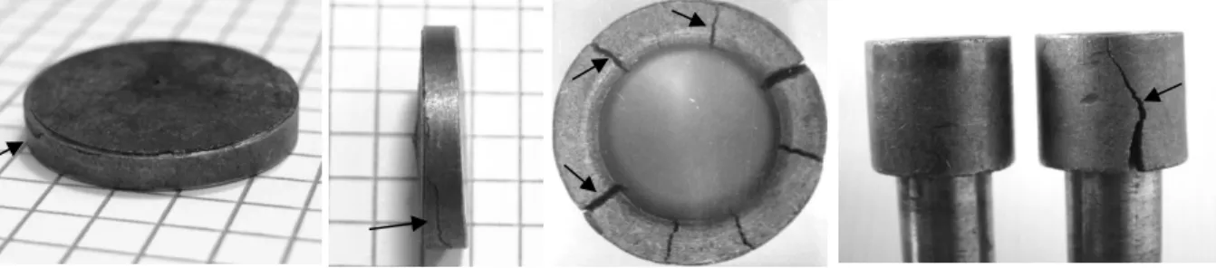
Figure 2: Cracks in outer parts of joints (shown by arrows) due to excessive or asymmetric PEMF.
The PEMF parameters must be well adjusted for joining powder metallurgy parts, which are characterized by increased brittleness and have residual porosity. When pressed, it is important to ensure the correct value of compressive forces. The surface of the substrate should not have scoring or unevenness. The gap between the connected parts and intensity of applied PEMF should be chosen as optimal. Otherwise, cracks can appear as a result of excessive or asymmetric PEMF (Fig.2). At optimum compression, the joining of cylindricl parts is uniform by the cross- section with no air gap between the parts. On the other hand, insufficient and assymetric PEMF creates a poor connection featured by low mechanical strength and gaps around the perimeter of the joint. There is a need for adequeate non-destructive testing (NDT) tools to evaluate the strength and uniformity of connections obtained by PEMF in order to establish the optimum
1 2 3
1 2 3
A B C
PEMF parameters and ensure the quality of the final products. Of the standard methods for testing welds, which include ultrasonic testing, eddy current and radiography (Ray et al., 2000), ultrasonic testing is the most promissing for assessment of PEMF joints. However, the joints obtained by PEMF compression are not as strong as welded seams, since there is no mutual penetration of materials. In addition, the specific structure and porosity of powder metallurgy parts, particularly compounds such as bronze graphite, cause a strong attenuation of high- frequency ultrasonic waves. Ultrasonic methods based on measuring the transmittance and reflection of ultrasonic waves have been approved in industrial research and in practice to evaluatethe bonds between metal, metal-polymer and composite parts (Adams and Cawley, 1988; Roach et al., 2009). The purpose of the study was to test the sensitivity of ultrasonic methods for recognizing tight and weak connections of powder metallurgy parts of various sizes obtained by PEMF.
2 Materials and Methods
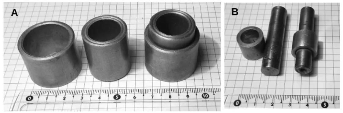
The testing objects were joints of powder metallurgy parts of two types: “bush-on-bush” and
“bush-on-rod” (Fig.3, Table 1). The bushes intended for antifriction operation were obtained from bronze graphite powder by sintering, where the base material was copper with a content of tin and graphite of 9 and 3%, respectively. The residual porosity reached 12-15%.
Figure 3: Examined types of joints: A – “bush-on-bush”; B – “bush-on-rod”
Table 1: Sizes of parts
Type of joint “Bush-on-bush” “Bush-on-rod”
Part Outer bush Inner bush Bush Rod
Parameter OD WT L OD WT L OD WT D L
Size, mm 32 3.0 30 26 3.5 36 16 2.5 11 50
OD is outer diameter, WT is wall thickness, D is diameter, L is length.
The parts were connected by radial compression realized with a inductor coil providing the values of the magnetic and electric components of the PEMF to 835 A/m and 17960 V/m. The
A B
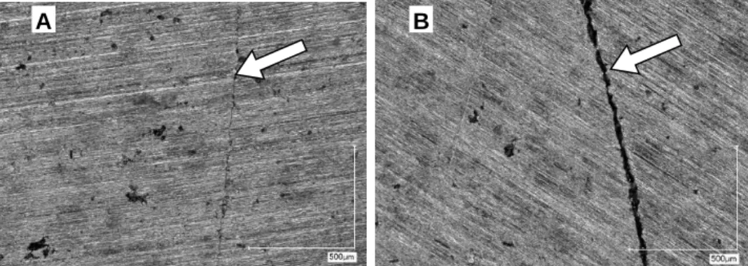
compressed parts were subjected to PEMF in the characteristic "near zone" formed at distances significantly shorter than the PEMF wavelength. Tight and weak bonded zones of the parts were obtained by applying the full value and the partial value of PEMF. Differences in joining grade were confirmed by microscopic observation the bonded zones in the cross sections (Fig.4). The differences in the optically visible gaps between the inner and outer bushings varied from zero to several tens of microns.
Figure 4: Microscopic images of tight (A) and weak (B) bonded zones in “bush-on-bush” joints at magnification x200. Arrows denote contact lines between bushes. Black dots are pores in powder bronze graphite.
Two methods of ultrasonic testing were compared: 1) the pulse-echo method using a commercial flaw detector; 2) the time-of-flight (TOF) method implememted in the custom system. The pulse-echo method was conducted in accordance to the standards EN ISO 16810:
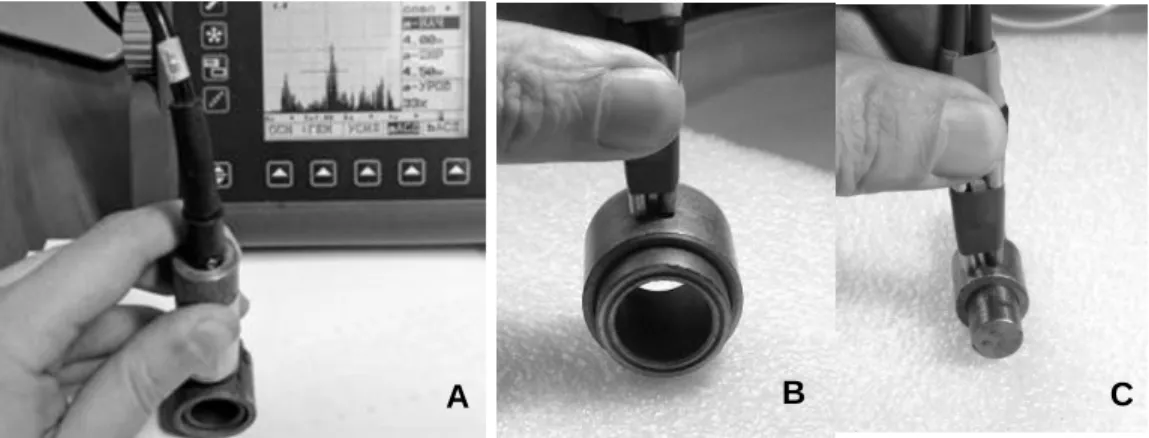
2014 “Non-destructive testing - Ultrasonic testing - Transmission technique” (ISO 16823: 2012) and EN ISO 16811: 2014 “Non-destructive testing - Ultrasonic testing - Sensitivity and range setting”. An ultrasonic flaw detector USM-25 from Krautkramer GE Inspection Technologies GmbH (Fig.5A) was used in the thickness measurement mode, previously calibrated for bronze graphite. A dual-element transducer Olympus 01JJ4L with a working frequency of 3 MHz was chosen taking into account the high attenuation of ultrasound in bronze graphite at higher frequencies. The design of the split sensor allowed to minimize the blind zone and to reduce the noise level.The TOF method was implemented by a pair of custom quasi-point transducers with a working frequency of 2 MHz. The transducers rigidly fixed at a distance of 5 mm between the centers were applied to the outer surface of the bushes as shown in Fig.5, B and C. Ultrasonic signals were acquired by an experimental measurement setup with the following parameters:
excitation by a 2-period syne tone-burst with a Gaussian envelope 140 V p-t-p; sample rate of 30 MHz; 10-bit A/D converter. Using TOF, it became possible to have access to small cylindrical objects with a small radius,similar to the case “bush-on-rod”. In addition, radiographic tests were done by a mobile industrial x-ray apparatus SMART EVO 200D of YXLON. The apparatus has a focal spot of 1.0 mm and a radiation power with a constant potential of 750 W, providing high performance, short exposure time and high resolution. The testing procedure was carried out according to the standard EN ISO 17636-1:2013 “Non-destructive testing of welds: Radiographic testing”. The translucency regimes were adjusted experimentally using samples of joints. X-ray films were examined visually after standard chemical treatment.
A B
Figure 5: Ultrasonic testing of “bush-on-bush” joints by pulse-echo method (A) and “bush-on- bush” and “bush-on-rod” joints by TOF method (B andC).
3 Results and Discussion
Figure 6: Radiographic testing of “bush-on-bush” (A andB) and “bush-on-rod” (C and D) joints, where A and C images correspond to tight joining and B and C images to weak one. Gap zones are denoted by circle and rectangles. Upper row in A and B shows circumferetial views and lower row shows axial views in x-ray films.
X-ray films revealed connection defects in weak joints of both types were revealed in x-ray films.
The gaps between the outer and inner parts in these joints were visualized both in the circumferential and axial view images (Fig.6). The difficulty of providing images with emphasized gaps was to find the appropriate exposure time and angle of transmission. This was only possible by multiple iterations. In addition, x-ray images didn’t provide a quantitative assessment of the mechanical toughness of the joints. In the ultrasonic testing in the pulse-echo mode, bottom reflection signals from the inner surfaces were obtained and surved to compare weak and tight connections. Examples of echograms taken on the USM-25 display are shown in
B C
A
A B C D
Fig.7 A and B. In the case of proper adhesion between the joint parts, ultrasonic wave could freely pass through the boundary between the outer and inner bushes and be reflected from the inner surface of the inner bush’s wall. Thus, the echo signal had a delay corresponding to the double wall thickness in both directions. In the case of a weak joining, the air gap between the outer and inner parts prevented through propagation of ultrasound and the echo signal had a twice shorter delay due to complete reflection from the inner surface of the outer part. In addition, due to the high attenuation of ultrasound in powder metal bronze graphite at 3 MHz and a longer propagation path, echo signals in the tight joint were more attenuated comparing with the weak one. Dissipation of ultrasonic energy in bronze graphite also caused wider reflection peaks than those that are typically observed in products made of cast metal.
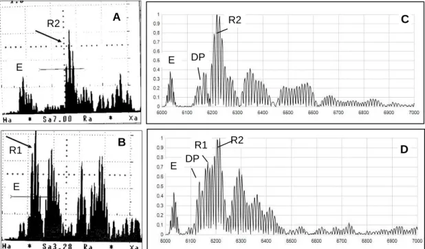
Figure 7: Ultrasonic signals obtained in “bush-on-bush” joints by pulse-echo (A andB) and TOF (C and D) methods, where A and C – tight joining; C and D – weak joining; signs on graphs: E – trace of excitation; DP – direct propagation; R1 – reflection from interface between bushes; R2 – reflection from inner surface of inner bush.
TOF signals obtained in the same samples and normalized by the peak amplitude are shown in Fig.7 C and D. It exhibits similar features, such as the absence of a noteceable response from the bonded zone between the bushes in the case of tight contact and appearance of this response (R1) in the case of weak contact. The bottom reflection from the inner bush (R2) is the predominant peak in both cases due to better penetration of ultrasound through the boundary at a lower frequency of 2 MHz. The ratio of R2 to R1 can be a quantitative measure of the joint’s toughness.
C
E DP A R2
E
R2
D DP
R1 R2 E
B
E R1
.
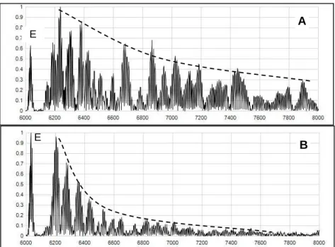
Figure 8: Ultrasonic signals obtained by TOF method in “bush-on-rod” joint: A – tight joining.
B – weak joining; E denotes excitation trace; curved lines are approximations of signals damping.
In small parts of the “bush-on-rod” joint with a large scurvature of the surface, only the TOF method was applicable. A comparison of tight and weak joining is shown in Fig.8. Due to the more complex wave paths in the “bush-on-rod” joint, including multiple reflections from the opposite surface and from the butt ends of the rod, the responce pattern in the case of a tight joining (Fig.8A) was rich in an amount of peaks and had a relatively longer reverberation time compared with the case of weak joining (Fig.8B). The weak joining (Fig.8B) had a more regular pattern, where multiple echoes from the boundary between the bush and the rod predominated, and the entire pattern resembled a classic ringdown pattern in flat objects (Adams and Cawley, 1988). The area under the approximation curve of ringdown patterns of normalized signals can serve as a quantitative parameter of the joint’s integrity.
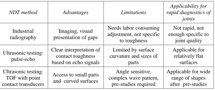
Comparison of the advantages and limitations of the examined methods and their applicability for the rapid diagnostic of joints is given in Table 2. The results of the study showed that the ultrasonic TOF method is the most universal in terms of accessibility to objects with a wide range of shape and size, while the wave pattern can be more complex and interpretation of individual peaks is more complicated than in the pulse-echo method. However, the latter circumstance can be avoided using the integral approach, where the arrival times of individual peaks are not taken into account, but the diagnosis is based on the signal’s intensity area over time. The standard pulse-echo method is suitable for testing large objects with a relatively low curvature of the surface. Both methods showed the applicability to the testing of joints of powder metal parts with high ultrasonic attenuation using transducers in a relatively low frequency band (2-3 MHz).
A
B E
E
Table 2: Comparison of applicability of different NDT methods for assessment of joints quality
4 Conclusions
1. In the current study, the sensitivity of two ultrasonic methods: pulse-echo and TOF to the mechanical integrity of the connection of powder metallurgy parts by the pulsed electromagnetic compaction were demonstrated.
2. Obtaining quantitative relationships between ultrasonic parameters and the mechanical strength of joints for industrial quality assurance can be the subject of further research investigation.
References
Adams, R.D, Cawley P., 1988. A review of defect types and nondestructive testing techniques for composites and bonded joints. NDT International, 21(4), pp.208-222.
Mironovs V., Boiko I., Kolbe M., 2015. Application of pulse plectromagnetic pield for joining of powder details. In:Solid State Phenomena, 9th International Conference MSM-2013 (Mechatronic Systems and Materials), Vilnius, Lithuania, pp.264-270.
Raj B., Subramanian C.V., Jayakumar T., 2000. Non-destructive testing of welds. Woodhead Publishing, Series in Welding and Other Joining Technologies, Alpha Science International Ltd., Oxford.
Roach D, Rackow K., Duvall R., Nelson C., Moore D., 2009. Nondestructive inspection of adhesive metal-to-metal bonds. U.S. Automotive Materials Partnership Report DE-FC26- 02OR22910 on Project NDE601 to Department of Energy, Washington, D.C.
Selcuk C., Bond S., Woollin P., 2010. Joining processes for powder metallurgy parts: a review.
Powder Metallurgy, 53 (1), pp.7-11.
NDT method Advantages Limitations
Applicability for rapid diagnostics of
joints Industrial
radiography
Imaging, visual presentation of gaps
Needs labor consuming adjustment, not specific
to toughness
Not rapid, not enough specific to
joint quality Ultrasonic testing:
pulse-echo
Clear interpretation of contact toughness based on echo signals
Limited by surface curvature and sizes of
parts
Applicable for relatively flat
surfaces Ultrasonic testing:
TOF with point contact transducers
Access to small parts and curved surfaces
Angle sensitive, complex wave pattern,
pre-studies required
Applicable for wide range of shapes after pre-studies