Model-Driven Software Migration into Service-Oriented Architectures
Andreas Fuhr · Tassilo Horn · Volker Riediger · Andreas Winter
Received: date / Accepted: date
Abstract This paper proposes model-driven techniques to extend IBM’s SOMA method towards migrating legacy sys- tems into Service-Oriented Architectures (SOA). The pro- posal explores how graph-based querying and transforma- tion techniques enable the integration of legacy assets into a new SOA and how these techniques can be integrated into the overall migration process. The presented approach is ap- plied to the identification and migration of services in an open source Java software system.
Keywords Software migration·Reengineering·Model- Driven Software Development·Service-Oriented Architec- ture
A. Fuhr
University of Koblenz-Landau Tel.: +49 (261) 287-2705 Fax: +49 (261) 287-100-2705 E-mail: afuhr@uni-koblenz.de T. Horn
University of Koblenz-Landau Tel.: +49 (261) 287-2745 Fax: +49 (261) 287-2721 E-mail: horn@uni-koblenz.de V. Riediger
University of Koblenz-Landau Tel.: +49 (261) 287-2706 Fax: +49 (261) 287-2721 E-mail: riediger@uni-koblenz.de A. Winter
Carl von Ossietzky University Oldenburg Tel.: +49 (441) 798-2992
Fax: +49 (441) 798-2196
E-mail: winter@se.uni-oldenburg.de
1 Introduction
Today, almost every company runs systems that have been implemented a long time ago. These systems, and even those that have been developed in the last years, are still under adaptation and maintenance to address current needs.
Adapting legacy software systems to new requirements of- ten needs to make use of new technological advances.
Business value of existing systems can only be preserved by transferring legacy systems into new technological sur- roundings. Migrating legacy systems, i. e. transferring soft- ware systems to a new environment without changing the functionality (Sneed et al 2010), enables already proven ap- plications to stay on stream instead of passing away after some suspensive servicing (Rajlich and Bennett 2000).
A technological advance promising better reusability of software assets in new application areas is provided by Service-Oriented Architectures (SOA). SOA is viewed as an abstract, business-driven approach decomposing software into loosely-coupledservicesenabling the reuse of existing software assets for rapidly changing business needs (Gold et al 2004). A service is viewed as an encapsulated, reusable and business-aligned asset with a well-definedservice spec- ificationproviding an interface description of the requested functionality. The service specification is implemented by a service component which is realized by aservice provider.
Its functionality is used by service consumers (Arsanjani et al 2008).
Migrating legacy systems to services enables both, the reuse of already established and proven software compo- nents and the integration with new services, including their orchestration to support changing business needs. In order to gain most benefit from a migration, a comprehensive ap- proach supporting the migration process and enabling the reuse of legacy code is required. The work presented here
is part of the SOAMIG1project, which addresses the semi- automatic migration of legacy software systems to Service- Oriented Architectures, based on model-driven techniques and code transformation.
Software development and maintenance projects require a clearly defined methodology. In contrast to cold-turkey approaches, Chicken Little (Brodie and Stonebraker 1995) provides an incremental approach towards migrating com- plete systems. Another general migration approach targeting on outsourcing migration projects is given by the reengi- neering factory (Borchers 1997). Data migration is sup- ported by the butterfly approach (Wu et al 1997) and the SMART-approach (Lewis and Smith 2008) assist in planing migration projects. For a comprehensive overview about mi- gration strategies, see (Sneed et al 2010). TheReMiP (Ref- erence Migration Process)provides a generic process model for software migration (Sneed et al 2010). Major activities in all software migration processes dealing with legacy code includelegacy analysisandlegacy conversion. Legacy anal- ysis aims at understanding legacy systems and identifying software assets worth to be transferred into the new environ- ment. Legacy conversion supports the technical migration of legacy assets by wrapping or transformation. In addition, a strategy to design the target architecture is needed.
In architecture migration projects, target architectures try to support most characteristics of new architectural paradigms. But economic migration requires converting of most of the legacy system with low effort. Thus, reasonable target architectures between optimal architectures for new systems and best reuse of legacy assets have to be defined incrementally (Zillmann et al 2010).
This paper focuses on applying model-driven techniques for migrating legacy assets to SOAs. Various strategies to design SOAs exist (Thomas et al 2010). According to Martin (2009), one of the best-known methods is IBM’s SOMA method. Service-Oriented Modeling and Architec- ture (SOMA) provides a process model for SOA develop- ment and evolution, which serves here as a methodological framework to identify and extend migration activities and their technological support. It includes seven incremental and iterative phases for identifying, specifying and imple- menting services (Arsanjani et al 2008). In the first place, SOMA is designed to develop SOAs from scratch and does not provide direct support for integrating legacy assets.
The extension of SOMA towards migration, presented here, is based on model-driven strategies. Models represent different views on software systems including business pro- cess models, software architecture and programming code (Winter and Ziemann 2007). Legacy analysis and conversion is based on queries and transformations on these models. In
1 This work is partially funded by the German Ministry of Education and Research (BMBF) grant 01IS09017C/D. See http://www.soamig.de for further information.
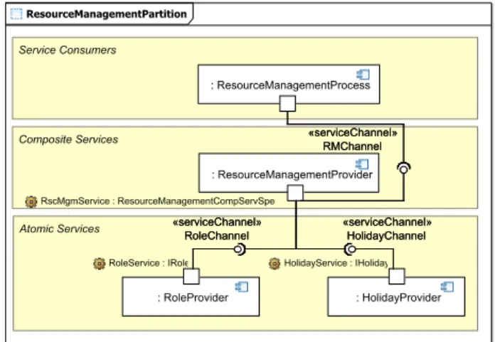
Fig. 1 Goal of this paper: composition of services in the target SOA design
this paper, theTGraph approach(Ebert et al 2008) is applied as one possible model-driven technology. By migrating ex- emplary services in the open source software GanttProject (GanttProject 2009), it will be shown how SOMA can be extended by model-driven technologies to provide a com- prehensive methodology to SOA development, including a broad reuse of legacy code assets.
This paper complements Fuhr et al (2010b), which sketched the initial graph-based approach for extracting and transforming a single service, to a capacious approach to migrate legacy systems to SOA systems. The application of graph-based reengineering and migration techniques to SOA migration is explained by identifying and transforming three exemplary services in the open source software GanttProject (GanttProject 2009). Based on one example business pro- cess, it will be described
– how TGraph technology is applied to represent and an- alyze legacy code supporting service identification and realization decisions,
– how SOMA is applied to specify and design services and – how TGraph technology is applied to transfer legacy
code into a service implementation.
Figure 1 shows the service-oriented target architecture, modeling the composition of a service that provides capa- bilities tomanage project resources. The composite service uses two atomic services to provide its functionality to the service consumer. In the remaining paper it will be described how to identify these three services and how to implement them by reusing legacy code (Fuhr 2009).
The remaining paper is organized as follows: Section 2 describes the SOMA method in more detail and motivates where SOMA has to be extended by model-driven reengi- neering techniques. Section 3 describes the TGraph technol- ogy to provide legacy analysis and legacy conversion and Section 4 introduces tools supporting the approach. In Sec-
Business Modeling
Solution Management
Service Identification
Service Specification Service
Realization Service
Implementation Service Deployment
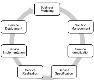
Fig. 2 The seven SOMA phases
tion 5 the integrated method is applied to identify, to spec- ify, to realize and to implement three services by reusing the GanttProject legacy code. Section 6 contrasts the inte- grated SOA migration approach presented here with current work in model-driven software analysis and migration. Fi- nally, Section 7 summarizes and reflects the obtained results.
2 Service-Oriented Modeling and Architecture (SOMA) and Software Migration
SOMA (Arsanjani et al 2008) is an iterative and incremental method to design and implement service-oriented systems, developed by IBM and still under research (latest published version: 2.4). SOMA describes how to plan, to design, to implement and to deploy SOA systems. SOMA is designed extensible to be able to include additional, specialized tech- niques supporting specific project needs. In the following, the seven SOMA phases shown in Figure 2 are introduced briefly. Section 2.1 then highlights where SOMA must be extended to support model-driven migration projects.
DuringBusiness Modeling, the state of a company is analyzed at the beginning of a project. As SOAs are tightly aligned to business concerns, it is necessary to clearly un- derstand the customer’s business. In this phase, all possible information about the following concerns is gathered:
– Business vision
– Business actors, use cases and processes
– Business goals and key performance indicators (KPIs) One main result of this phase is thebusiness modelwhich is a formalized view on these aspects.
Solution Managementadapts the SOMA method to the project needs. This includes choosing additional techniques
to solve project-specific problems. From a SOMA perspec- tive, this paper is located in Solution Management since it adapts SOMA to software migration issues, using model driven technologies.
DuringService Identification, SOMA uses three com- plementary techniques to identify service candidates, i.e.
functionality that may be implemented as service later in the new architecture.Domain Decompositionis a top-down method decomposing the business domain into functional areas and analyzing the business processes to identify ser- vice candidates. Goal-Service Modeling identifies service candidates by exploring the business goals and subgoals.
Legacy Asset Analysisfinally explores the functionality of legacy systems bottom-up. It is analyzed, which business processes are supported by what functionality of a legacy system. For that purpose, documentation, APIs or interfaces are explored to identify which functionality is provided.
The source code is only analyzed on a coarse-grained level, meaning it is analyzed which functionality exists and not how it is actually implemented. For each business function- ality supporting a business process, a service candidate is created. All three techniques are performed incrementally and iteratively. For each identified candidate, an initial ser- vice specification is created and a trace to the source of iden- tification is established.
Service Specificationdeals with describing the service design in detail. The initial service specification is refined, messages and message flows are designed and services are composed. This phase results in a comprehensive descrip- tion of the service design. SOMA uses an UML profile for Service-Oriented Architectures to describe the service de- sign. Later, the specification will be transformed into WSDL code for implementing the service as a Web Service (as it is proposed by SOMA).
Service Realizationdecides which services will be im- plemented in the current iteration and constitutes how to im- plement them. First, aService Litmus Test (SLT)is executed to identify service candidates that should be exposed. The SLT is a set of criteria to evaluate usefulness and value of each service. After having chosen a set of services, the im- plementation strategy has to be defined. Encapsulation of services allows the choice of different ways to implement each service. Common strategies to form new service com- ponents are
1. implementation from scratch,
2. wrapping of larger legacy components or 3. transforming the required legacy components.
After having decided on an implementation technique, le- gacy systems require fine-grained analysis. Functionality that is able to implement services has to be identified in the legacy code. In addition, it is important to clearly un- derstand how this functionality is embedded in the legacy
system, since it has to be separated to build a self-contained service. Finally, the implementation design specifying how to implement the service, is created. In addition, patterns are used to create a framework which is able to integrate the service implementation into the service design.
During theService Implementationphase, services are actually implemented. According to the decisions derived in the Service Realization phase, services are developed, wrap- pers are written, or legacy code is transformed. Finally, all services are orchestrated and message flows are established.
The last phase isService Deployment. It deals with ex- posing the services to the customer’s environment. Final user-acceptance tests are performed and the SOA is moni- tored to verify that it performs as expected.
2.1 Extending SOMA for Model-driven Migration
Although being suited for SOA development projects, the SOMA method lacks of direct support for migrating legacy software towards SOAs. In the following, four extension points and their relevance to SOA migration projects are de- fined, where SOMA must be leveraged in order to support SOA migration projects.
Extending service identification.Service Identification is one of the core phases in SOA development as well as in SOA migration projects. As migration projects aim at pre- serving functionality without adding new features, identify- ing the functionality a legacy system provides is very im- portant. Therefore, techniques to identify functionality in legacy code are required. SOMA does not describe how to analyze legacy systems. At this point, additional methods and techniques must be included. In Section 5.3, we extend SOMA by a model-driven technique to reverse-engineer legacy code into an appropriate TGraph, which enables queries and transformations to identify service candidates.
Extending service specification.In plain development projects, Service Specification is a straight forward engi- neering phase. In migration projects, Service Specification combines forward engineering (design of the target architec- ture and orchestration of services) with reverse-engineering tasks (derive service operations and message design from le- gacy code). Therefore, techniques to support the forward de- sign by analyzing legacy systems are needed. Service Spec- ification describes the service in detail. To gather the infor- mation needed for the design, messages and message param- eters can be derived from legacy code. We extend SOMA to identify useful legacy code in Section 5.4.
Extending service realization. In SOA Migration projects, it is important to identify which of the services can actually be implemented by reusing legacy code andhow the code can be reused. In SOMA, legacy functions usu- ally arewrappedand then exposed as services. This has sev- eral drawbacks. The legacy system must still be maintained
and in addition, the wrapper must be created and maintained later, too. A different approach is totransformlegacy func- tionality into a service implementation. However, code may not be suited to form a self-contained and loosely-coupled service and might therefore require a re-implementation of the functionality (Nasr et al 2010). SOMA does not describe how to implement services by reusing legacy code. In Sec- tion 5.5, a static and a dynamic approach are presented to analyze legacy systems fine-grained in order to understand the implementation of legacy functionality.
Extending service implementation. In migration projects, service implementation is influenced by the choice of migration strategy (re-implementation, wrapping of trans- formation). In contrast to implementation in development projects, this phase focuses more on reusing existing code.
Therefore, techniques are needed to extract legacy code and to make it available to the target implementation. SOMA does not include techniques to transform legacy code into services. In Section 5.6 it is demonstrated how graph trans- formations are used to transform legacy code into service implementations.
This concludes the description of the SOMA method.
The next section introduces the TGraph approach that is used as technological foundation of our extensions to SOMA. In Section 4, the integration of the TGraph approach into the overall migration tools environment is described and in Section 5, the extended SOMA method is then applied to the migration of GanttProject.
3 Model-Driven Migration: The TGraph Approach The extension of SOMA towards migration, presented in this paper, is based on model-driven strategies. Models (in- cluding code) represent different views on software sys- tems including business process models, software architec- ture and program source code. In particular, migrating le- gacy systems to SOA requires an integrated view on busi- ness processes, architecture and code (Winter and Ziemann 2007) to be able to identify and extract services. Therefore, an integrated representation of all these artifacts is essential.
Model-driven approaches provide these technologies:
1. formal definition of valid models (metamodels), 2. querying of models (query languages) and
3. transformation of models (transformation languages).
Today, many model-driven approaches are known.
Metamodels can be described by using the OMG’sMeta Ob- ject Facility(MOF (OMG 2006)) or INRIA’s KM3 (Eclipse 2007). Well-known transformation languages include QVT (Query/View/Transformation (OMG 2007)) or ATL (Atlas Transformation Language (ATLAS Group 2009)). All these approaches are suited for extending SOMA. However, in this
paper, a graph-based approach is used that has already been applied in various reverse- and reengineering projects (Ebert et al 2008). The TGraph approach is a seamless graph- based approach. Models are represented by graphs conform- ing to agraph schema(a metamodel). They can be queried with the graph query languageGReQL(Graph Repository Querying Language (Bildhauer and Ebert 2008)) and can be transformed using GReTL(Graph Repository Transforma- tion Language (Ebert and Horn [To appear])).
Following the three model-driven technologies men- tioned above (metamodels, query languages and transforma- tion languages) their realization in the TGraph approach is described in the following subsections. Section 3.1 describes the kind of graphs used in the TGraph approach, includ- ing a short overview about the metamodeling foundations.
Section 3.2 gives an introduction to querying TGraphs with GReQL and Section 3.3 depicts the GReTL transformation language.
3.1 Metamodeling: TGraphs and Metamodels
Migration projects require the exploration of various sources like business processes, legacy architecture or legacy code.
For integrated analyses, it is necessary to store all data in an integrated model, the repository. Metamodeling deals with describing the structure of this repository.
The presented approach uses TGraphs for storing arti- facts. A TGraph is a directed graph where all nodes and edges are typed and may contain attributes. Additionally, edges and nodes are ordered globally and all incident edges of a node have a local order. Edges are first class citizens, so the navigability is always bidirectional and does not de- pend on the edge’s direction. This also enables reasoning on edges directly. In sparse graphs, which usually occur in code and model representations, this also provides more efficient graph traversal, compared to approaches considering edges as tuples of start and end node.
The graph libraryJGraLab (Java Graph Laboratory2) provides a convenient and efficient API for accessing and manipulating TGraphs.
Each TGraph is an instance of aTGraph schema. In a model-driven sense, a TGraph schema is a metamodel for a class of TGraphs and defines edge and node types, includ- ing their attributes. Additionally, both node as well as edge types can specialize other node and edge types and multi- ple inheritance is supported. Such schemas are specified by using a UML profile calledgrUML (Graph UML), a tool- ready subset of CMOF slightly more expressive than EMOF (Bildhauer et al 2009). In grUML diagrams, node and edge types and their attributes are specified with UML. Classes
2 http://jgralab.uni-koblenz.de
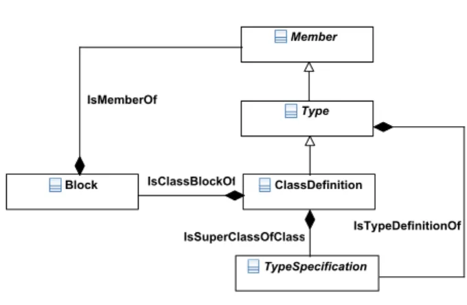
Fig. 3 Small extract of the Java metamodel
are used to define node types and associations (or associa- tion classes) are used to define edges. GrUML schemas can be created with basically any UML editor. There are tools to convert such schemas from XMI to the internal format of JGraLab. Given a TGraph schema, JGraLab generates Java source code for an object-oriented API for accessing and modifying TGraphs conforming to that schema.
Among others, a schema covering the complete abstract syntax of the Java programming language exists.
Figure 3 shows a small extract of the Java metamodel specifying class members
ClassDe f initionIsClassBlockO f
→ BlockIsMemberO f
→ Member
and the superclass hierarchy ClassDe f initionIsSuperClassO f Class
→ TypeSpeci f ication All examples in Section 3 are based on this extract.
Using a custom parser (Baldauf and Vika 2009), Java source code, class files and jar files can be converted into a TGraph conforming to this Java schema. These graphs are subject to advanced analysis and transformation using the query and transformation languages described in the next subsections.
3.2 Query Language: GReQL
For exploring the information stored in the repository, a querying language is needed. GReQL (Graph Repository Query Language, (Kullbach and Winter 1998; Bildhauer and Ebert 2008)) is a textual, schema-aware querying language for TGraphs. One of the most commonly used language ele- ments is thefrom-with-report (FWR)clause. Thefrompart is used to declarevariablesand bind them todomains. In the withpart,constraintscan be imposed on the values of these variables. Thereportpart is used to define the structure of the query result.
A sample query for retrieving all super- and subclasses of a class with nameHumanResourcein a graph conform- ing to the Java schema in Figure 3 is depicted in Listing 1. In migration projects, such queries help to identify the class hi- erarchy in object-oriented legacy systems (in Figure 11 this query will be used as one part to identify static dependencies of classes).
1 from e : E{ I s S u p e r C l a s s O f C l a s s }
2 with s t a r t V e r t e x ( e ) . name = " HumanResource " or
3 endVertex ( e ) . name = " HumanResource "
4 r e p o r t s t a r t V e r t e x ( e ) . name , endVertex ( e ) . name
5 end
Listing 1 A GReQL query to find direct superclasses and subclasses
In thefrom part, the variablee is bound to all edges of type IsSuperClassOfClass one after the other (Looking at Figure 3 these edges are modeled by theIsSuperClasOf- Classassociation betweenClassDenitionandTypeSpeci- cation). The constraint defined in the withclause requires that thenameattribute of the node acting as source or target of such an edge matches the string “HumanResource”. The report clause defines the structure of the results as tuples where the entries are pairs of the names of the superclass and subclass. For eachIsSuperClassOfClassedge which sat- isfies the constraint, a tuple is added to the result multiset (bag).
One of GReQL’s especially powerful features are reg- ular path expressions, which can be used to formulate queries that utilize the interconnections between nodes and their structure. Therefore, symbols for edges are introduced:
−−>and<−−for directed edges and<−>if the direc- tion should not be taken into account and<>−−or−−<>
for edges modeling containment relationships. Additionally, an edge type written in angle brackets may follow the edge symbol. These symbols can be combined using regular op- erators: sequence, iteration (∗and+), alternative (|) and so on.
Listing 2 shows a query for finding member classes. In migration projects, migrating member classes makes it nec- essary to identify in which class the member class is nested.
In addition, member classes must be migrated in order to preserve functionality. Such a query can help identifying these member classes.
1 from o , m : V{ C l a s s D e f i n i t i o n }
2 with o <−−{I s C l a s s B l o c k O f } <−−{IsMemberOf } m
3 re por t S et m end
Listing 2 A query using regular path expressions to find member classes
Two variables of type ClassDenition are defined. If the ClassDenition mis a member ofo(e.g. a path like the one depicted in thewithclause exists), the member classm will be reported. Looking at Figure 3, this path is modeled in the metamodel as follows:
ClassDe f.IsClassBlockO f
→ BlockIsMemberO f
→ ClassDe f.
3.3 Transformation Language: GReTL
Up to now, the data structure has been defined by meta- models and information can be retrieved by GReQL queries.
Now, a technique to transform (change) models is needed. In migration projects, such transformations play an important role and are used for various activities like
– Reverse engineering (transformation of models into more abstract representations, e.g. code to architectural views)
– Conversion (transformation of source models into differ- ent target models, e.g. legacy code into a SOA service) – Forward engineering (transformation of models into a
more detailed representations, e.g. design model into class stubs)
TheGReTLtransformation language (Graph Repository Transformation Language) is a Java framework for pro- gramming transformations on TGraphs making use of the TGraph related GReQL language (cf. Section 3.2) (Ebert and Horn [To appear]).
Instead of creating a new transformation language in- cluding its own syntax from scratch, existing technologies were applied, namely JGraLab’s Schema API for describing imperative aspects and GReQL for declarative parts.
The idea of GReTL is to build a target TGraph schema by writing transformation rules as calls to methods pro- vided by the transformation framework. These methods cre- ate new elements in the target schema by delegating to meth- ods in JGraLab’s Schema API. GReQL queries given as ad- ditional parameters in transformation rules specify declara- tively which instances of this new type have to be created in the target graph.
An example rule for creating a node class in the target schema and its appropriate instances is depicted in Listing 3.
1 from t : V{Type}
2 with t . name =~ ' .∗[ Rr ] e s o u r c e .∗'
3 r epo rtSet t end
4==> C r e a t e V e r t e x C l a s s uml . C l a s s ;
Listing 3 GReTL rule for creating a node class and instances thereof
The parameter uml.Class to the transformation opera- tion CreateVertexClass is the fully qualified name of the
new node class to be created in the target schema. The query given before the==>is a GReQL query, which is evaluated on the source graph and returns the set ofTypeswhose name contains the substring “resource” (specified by a regular ex- pression). These types are used asarchetypesfor theuml.
Classnodes that are created in the target graph, i. e., for each of the selectedTypenodes, a newuml.Classnode is created in the target graph. The mapping of archetypes to the newly created nodes is saved and accessible in further rules. Fur- ther methods for creating edge types (including their edge instances), attributes and generalizations between edge and node classes are realized in an analogous manner.
The following section will describe how the TGraph ap- proach introduced in this section is integrated into the over- all migration tool set environment.
4 Migration Tool Set Environment
The previous section introduced the implementation of model-driven techniques by the TGraph approach. Com- bining tools implementing graph schemas as metamodels, GReQL as query language and GReTL as transformation language, the TGraph approach can be used for model- driven development. This section describes which tools are used in the overall SOA migration environment and how the TGraph tools fit into it.
4.1 Modeling Tools
For modeling, IBM’s Rational Software Architect for Web- Sphere Software v7.5.4 (RSA) is used as it supports SOMA by predefined model building-blocks, SOA patterns and a SOA UML profile (IBM Corporation 2009). The RSA is an integrated modeling and development tool supporting mod- eling with UML 2 and development of Java or C++ applica- tions. It supports various transformations like UML2Java or ServiceSpecification2WSDL.
In the SOA migration project presented in Section 5, the RSA is used for the following tasks:
– Design metamodels for repository (SOMA Solution Management phase): The metamodels are designed as UML class diagrams and exported as XMI files. A tool is then used to create a TGraph schema from that XMI file.
– Model business processes (SOMA Business Modeling phase): The processes are designed as UML activity di- agrams, exported as XMI file and then parsed into a TGraph for further exploration.
– Create service design (SOMA Service Identification and Service Specification phases): Using a UML profile for SOAs, the design of the services (service specification,
messages, implementation) is created. As described in Section 5.6, RSA’s transformation functionality is used to transform the service specification into WSDL inter- faces and the implementation framework into Java stubs.
– Generate service framework (SOMA Service Realiza- tion, Service Implementation and Service Deployment phases): Using the WebService Wizard provided by RSA, the WSDL interfaces and the implementation code are put together and fully functional services are gener- ated.
While covering all modeling aspects with the RSA, addi- tional tools are needed to handle legacy code. The following subsection describes legacy code parsers.
4.2 Legacy Code Parsers
In model-driven development, parsers play an important role. All kinds of artifacts are parsed and stored in a reposi- tory. For integrated analyses, legacy systems are parsed into a TGraph representation (model). For Java systems, the tool GraBaJa (Graph-Based Java, (Baldauf and Vika 2009))is used. GraBaJa is a Java API providing
– a Java 6 metamodel, – a Java parser and – a Java code generator.
The tool is used to parse Java legacy systems into a TGraph conforming to the Java 6 metamodel. In addition, a transformed Java TGraph can be parsed back into Java us- ing GraBaJa’s code generator.
Within the SOAMIG project, pro et con GmbH is devel- oping further industrial strength parser frontends for Java 6 and Cobol to be integrated to TGraph based software evolu- tion activities (Zimmermann et al 2010).
4.3 Tool Set-Up for Dynamic Analysis
In model-driven migration projects, many models are cre- ated, e.g. business process models, legacy architecture mod- els or legacy code models. Relations between model ele- ments – e.g. which code is executed during what business process – can hardly be identified by static analysis. There- fore, we use dynamic analysis in SOA migration projects to find relations between models and integrate them into the repository.
Dynamic analysis approaches execute a predefined sce- nario on a software system. The system under analysis is extended by functionality to trace which parts of the soft- ware are executed during this scenario (e.g. all method calls and returns are logged). This results in a log file describing which methods have been called during the scenario. This
Repository
AspectJ Tracing
Log-File Load
business processes
Instrument legacy system
Log execution of business processes
Log behavior of legacy system
Create trace links 2
1
3
4
Trace Analyzer Log
Server
Legacy System Business Process Tracer
Create workflow
Fig. 4 Tool Set-Up for Dynamic Analysis
information can be used for further analysis like exploring dynamic call dependencies.
In SOA migration, useful scenarios are naturally given by the business processes. As SOAs are tightly related to these processes, they are suited for dynamic analysis. In this paper, dynamic analysis using the workflow of business pro- cesses is used to
1. verify that business processes are supported by the le- gacy system (Service Identification, see Section 5.3.2) and
2. identify legacy code that is able to support business pro- cesses and therefore could be used to implement a ser- vice (Service Realization, see Section 5.5.2).
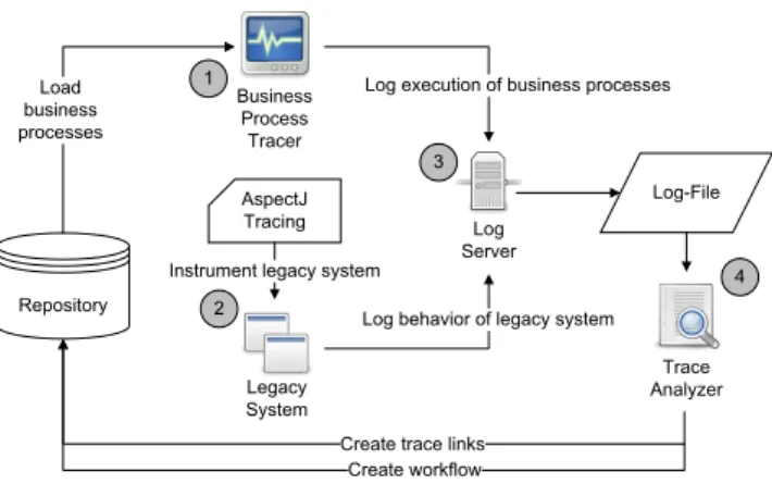
The tool environment shown in Figure 4 has been set up to run these analyses (Fuhr et al 2010a). The dynamic analysis is split into two parts:
– the definition of a storyboard for the scenario and – the execution of the scenario on the legacy system.
First, the business processes (which have been captured, modeled and parsed into the repository) are loaded into the Business Process Tracer (BPT). The BPT (1) allows to nav- igate through all processes and visualize each process as UML activity diagram. Selecting a business process, a user gets displayed a storyboard for one dynamic analysis run.
Following this storyboard, the user can then perform each business process step on the legacy system. Using the BPT, he can tell when each step starts and ends. This information is sent to alog server(3), tracing start and end of each step.
Second, the legacy system needs functionality to trace which code is executed during the scenario (2). In order to keep the legacy system as much unchanged as possible, we decided to integrate this tracing functionality by using as- pects. The aspect hooks into each method call and return and logs each call and return to the log server. As dynamic analysis produces a vast amount of tracing information, first filtering mechanisms – e.g. to filter out calls to GUI-related methods – can be established in this aspect, too.
Summarizing, when running a dynamic analysis, a user executes a given business process on the legacy system while logging when each step of the process starts and ends.
Meanwhile, the legacy system logs which code is executed during the scenario. All information is send to the central log server and stored as log file.
After finishing the dynamic analysis, the log files are post-processed by theTrace Analyzer(4). The Trace Ana- lyzer has two jobs:
– create trace links between methods and process steps and
– extract the real workflow of business processes.
First, the Trace Analyzer creates for each method that has been called during a business process step a trace link between this method and the process step. After this analy- sis, the repository has been extended by trace links telling which methods have been executed during each business process step. This information will be used in Section 5.5.2 to identify code that is able to implement a service.
Second, an instance of the real workflow of the business process is stored back to the repository. We discovered that business processes are often not executed as strictly as they have been modeled. For this reason, the BPT-GUI does not enforce the modeled ordering of the process steps. An al- ternative execution of a process is stored to the repository as additional workflow for this process. This information will be used in Section 5.3.2 to verify the business process model.
Merging this development environment and the TGraph approach with SOMA provides a comprehensive technique for SOA migrations. The following section describes how this technique is applied on extracting three services from GanttProject, a Java tool used for project management.
5 Merging SOMA and Model-Driven Approaches The previous sections motivated the need of extending SOMA for reusing legacy software assets in software mi- gration and shortly presented graph-based modeling, anal- ysis and transformation techniques including tool support.
The migration approach resulting in the extension of SOMA by TGraph-based techniques is applied to identify services from legacy code to support specification and realization de- cisions and to transform legacy code into service implemen- tations.
In the following subsections, an integrated SOMA and TGraph-based reverse-engineering and transformation is applied to the migration of GanttProject into a Service- Oriented Architecture (Fuhr 2009). GanttProject (GanttPro- ject 2009) is a project planning tool. It manages project re- sources and tasks and displays project schedules as Gantt charts. GanttProject is a Java system containing about 1200
ManageResource
ManageRole
ManageHoliday [hasHolidays]
[!hasHolidays]
[hasHolidays]
[!hasHolidays]
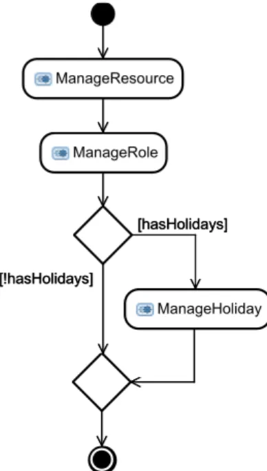
Fig. 5 TheResource Managementbusiness process
classes. The required migration is exemplified by identifying and migrating three services tomanage project resourcesby transforming legacy code.
5.1 Business Modeling
During the first phase in SOMA, the current state of the company is analyzed. Because services are tightly related to business processes, this phase establishes an important basis to identify which services are needed. One core result of this phase is the business model.
In this example, two project mangers have been inter- viewed to gather business processes for project manage- ment. One of the captured processes has been identified as core business process in project management: defining what resources are available to get work done.
Figure 5 shows the workflow of theResource Manage- mentbusiness process. First, general data (e.g. name, tele- phone or e-mail address) about a resource is entered during theManageResourcestep. Next, the role of a resource dur- ing the project – e.g. developer, tester or manager – is de- fined (ManageRole). If a resource is on holiday during the project, the time that the resource is not available can be specified in an optional step (ManageHoliday).
For industrial projects business modeling is far more complex. Experiences during the SOAMIG project showed, that finding the right granularity in the description of busi- ness processes to be able to model services supporting them is one of the main difficulties. As a lesson learned, a service designer should be involved during this phase.
At the end of this phase, a business process model has been created describing the business process as activity dia- gram. In the remaining phases, thisResource Management business process is used as continuous example. It will be described how to identify and implement services support- ing this business process using SOMA and the TGraph ap- proach.
5.2 Solution Management
Solution Management adapts the SOMA method to the cur- rent project needs. Extending SOMA by model-driven tech- niques to support software migration – as depicted in this pa- per – is located in this SOMA phase. This includes adapting the used tools (cf. Section 4) and techniques. To allow de- tailed analyses of the legacy system, it is necessary to store all information (e.g. legacy code, legacy architecture de- scriptions or business processes) in an integrated data struc- ture, therepository. Therefore, the metamodel of the repos- itory must support all languages used for modeling these ar- tifacts.
In this example, the Java sources of GanttProject and the business processes modeled as activity diagrams in Sec- tion 5.1 are to be stored in such a repository. The metamodel of the repository therefore has to support Java syntax and UML activity diagrams. The Java 6 part of our metamodel contains about 90 vertex and 160 edge types and covers the complete Java syntax. The activity diagram part contains 16 vertex and 14 edge types and covers the full UML 2.1 activ- ity diagram specification. Storing all information in an inte- grated data structure will later allow to add traces between the two domains and perform analyses over all data.
The GanttProject sources are parsed according to that metamodel. The activity diagram in Figure 5 is exported as XMI and then parsed into the same graph, resulting in a graph of 171198 nodes and 239359 edges.
After this phase, an integrated repository exists, con- taining a TGraph representation of the GanttProject Java sources as well as theResource Managementbusiness pro- cess modeled during Business Modeling (see Section 5.1).
This graph and the implicit knowledge on resource manage- ment will provide the foundation for service identification, service specification, service realization and service imple- mentation.
5.3 Service Identification
Service Identification explores all information available to find all services a customer needs to perform his tasks. As a reminder, services are coarse-grained, loosely-coupled and business-aligned software components. Sources to identify
1 from t : V{Type}
2 with t . name =~ ' .∗[ Rr ] e s o u r c e .∗'
3 re por t S et t end
4 ==> C r e a t e V e r t e x C l a s s uml . C l a s s ;
5
6 from t : keySet ( img_uml$Class )
7 reportMap t , t . name end
8 ==> C r e a t e A t t r i b u t e uml . C l a s s . name : S t r i n g ;
9
10 from c : keySet ( img_uml$Class ) ,
11 c2 : keySet ( img_uml$Class )
12 with c <−−{I s B l o c k O f } <−−{IsMemberOf }
13 <−−{^IsBreakTargetOf ,^
I s C o n t i n u e T a r g e t O f ,
14 ^ I s T y p e D e f i n i t i o n O f ,^ I s C l a s s B l o c k O f ,
15 ^ I s I n t e r f a c e B l o c k O f }∗
16 [<−−{ I s T y p e D e f i n i t i o n O f } ] c2
17 rep or t S et tup ( c , c2 ) , c , c2 end
18 ==> C r e a t e E d g e C l a s s uml . A s s o c i a t i o n
19 from uml . C l a s s to uml . C l a s s ;
20
21 from c : keySet ( img_uml$Class ) ,
22 c2 : keySet ( img_uml$Class )
23 with c (<−−{I s S u p e r C l a s s O f }|<−−{ I s I n t e r f a c e O f C l a s s })
24 <−−{I s T y p e D e f i n i t i o n O f } c2
25 rep or t S et tup ( c , c2 ) , c , c2 end
26 ==> C r e a t e E d g e C l a s s uml . IsA
27 from uml . C l a s s to uml . C l a s s ;
Listing 4 Simplified GReTL transformation from Java to UML
services from are business processes and goals as well as legacy systems.
5.3.1 Service Identification based on Legacy Analysis The identification of services from legacy systems requires a coarse-grained analysis. The graphical user interface of GanttProject is explored first and functionality to manage project resourcesis identified as one main feature of the soft- ware. Looking at the legacy code identifies the functionality providing the management of project resources.
Identifying functionality in legacy code is a challeng- ing task and still an open research issue (Kontogiannis et al 2007). In our approach, GReQL queries are used to identify this functionality in the GanttProject-TGraph and a corre- sponding GReTL transformation visualizes the query result.
String search on TGraphs is used to detect possible code ar- eas referring to “resources” and further interconnections of code objects are specified by regular path expressions. The resulting subgraph is transformed by GReTL into a TGraph conforming to a simple UML schema. Further XMI-based filters (cf. (Ebert and Winter 2006)) are used to render these structures in UML tools.
Listing 4 shows a GReTL transformation supporting coarse-grained legacy code analysis. For each legacy class or interface whose name contains “resource” (line 5), this
v1 Class
isAbstract = false
name = "HumanResourceManager"
v3 Class
isAbstract = false name = "HumanResource"
e9: Association
v4 Class
isAbstract = true name = "ResourceManager"
e16: IsA
e6: Association
e13: Association
v2 Class
isAbstract = false
name = "ResourceAssignmentImpl"
e4: Association e7: Association
e10: Association
e2: Association
e15: IsA
e3: Association
e14: Association
v5 Class
isAbstract = false name = "ProjectResource"
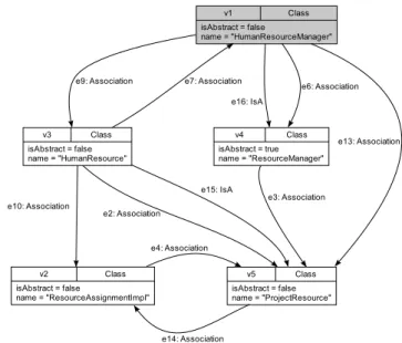
Fig. 6 Visualization of classes and interfaces possibly providing func- tionality to manage resources
transformation creates one UML class node in the target TGraph. In addition, associations are drawn between those class nodes whenever one node uses (e. g. by method calls or variable types) another node (lines 11-16). Inheritance be- tween types is represented by “IsA” edges (lines 17-22). For interfaces and abstract Java classes, their UML class coun- terparts are marked by appropriate attributes.
Of course, such queries are project specific and must be developed in the beginning of a project. However, once de- veloped, they can be reused in the remaining project. The generic SOAMIG process model (Zillmann et al 2011) com- prises a Conceptualization phase, which identifies automati- zation options and provides reusable analysis and transfor- mation techniques for recurring activities within the migra- tion project.
Looking at the visualized result of this GReTL trans- formation shown in Figure 6, the classHumanResourceM- anager (marked with gray background) implementing the interfaceResourceManagercan be identified as functional- ity to manage project resources. Based on this information, an initial service specification for the service candidateIRe- sourceManagementis created and traces to the legacy code are noted.
5.3.2 Service Identification based on Domain Decomposition
In addition to exploring the legacy system, the business model is analyzed to identify services. Based on the assump- tion that each business process should be supported by a ser- vice (Arsanjani et al 2008), business processes are analyzed to identify service candidates during Domain Decomposi- tion.
Fig. 7 Three initial services (in UML modeled as stereotyped inter- face) identified from legacy code and business model
TheResource Managementbusiness process in Figure 5 indicates that managing a resource may include managing its role and its holidays. Therefore, two additional service specifications are added to the initial service model shown in Figure 7. In this phase, no further information about the method signatures of the initial service specification is gath- ered. Method signatures and messages are added in the next increment of the service design, during Service Specifica- tion.
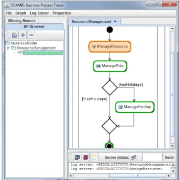
In order to verify that the legacy system really does support the two business processes (and is therefore suited for reusing functionality to implement the services), the dy- namic analysis set-up described in Section 4.3 is used to ex- plore which processes are supported by GanttProject. Fig- ure 8 shows the Business Process Tracer tool, visualizing theResource Managementbusiness process. While logging when each step of the process begins and ends, the process is executed on GanttProject. GanttProject has been extended by an AspectJ aspect logging each method call and return.
All information is sent to a central log server.
After the analysis, a Trace Analyzer processes the trace files to perform two tasks:
1. Create real workflow of the process 2. Map legacy code to business processes
Establishing the real workflow of the business processes gives hints where the business process model might have to be revised. The mapping between legacy code and business processes indicates if a process is supported by GanttProject or not: If any code is mapped to a process, it is supported by GanttProject. In addition, the mapping between legacy code and business processes will later be used to find code that is able to implement services, as will be described in Section 5.5.2.
At the end of this phase, three service candidates have been identified from legacy code and from the business pro-
Fig. 8 The BPT tool used to trace the execution of theResource Man- agementbusiness process
cess model: The IResourceManagementservice has been derived from legacy code and the IHolidayand IRole ser- vices have been derived from the business process model.
Traces to their sources of identification have been noted, too.
In the following SOMA phases, the services are specified in more detail.
5.4 Service Specification
During Service Specification, the initial service specifica- tions are refined. Aservice providercomponent is created which will later implement the service specification. In ad- dition, message flows are created to enable communication with services. The goal of this phase is to create an compre- hensive service design specifying all aspects of the external view on the service (i.e. how a service is seen by consumers).
Implementation details will be designed later, during Sec- tion 5.5.
In this example, formethod parametersin the legacy in- terface,request messagesare created that are passed to the service. Forreturn typesin the legacy system,response mes- sagesare defined that will be returned by the new service.
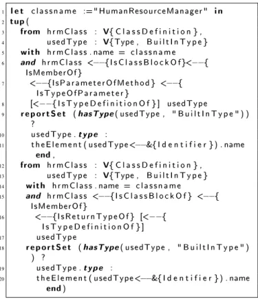
Request and response messages can be derived from legacy code. Listing 5 shows a GReQL query taking an interface or class name as input and returning method parameters (lines 3-11) and return types (lines 12-20) as output. This informa- tion is used to derive message parameter types from legacy code.
1 l e t c l a s s n a m e :=" HumanResourceManager " i n
2 tup (
3 from hrmClass : V{ C l a s s D e f i n i t i o n } ,
4 usedType : V{Type , B u i l t I n T y p e }
5 with hrmClass . name = c l a s s n a m e
6 and hrmClass <−−{I s C l a s s B l o c k O f}<−−{ IsMemberOf }
7 <−−{IsParameterOfMethod } <−−{ IsTypeOfParameter }
8 [<−−{ I s T y p e D e f i n i t i o n O f } ] usedType
9 re po r t Set ( hasType ( usedType , " B u i l t I n T y p e " ) )
?
10 usedType . type :
11 theElement ( usedType<−−&{ I d e n t i f i e r }) . name end ,
12 from hrmClass : V{ C l a s s D e f i n i t i o n } ,
13 usedType : V{Type , B u i l t I n T y p e }
14 with hrmClass . name = c l a s s n a m e
15 and hrmClass <−−{I s C l a s s B l o c k O f } <−−{ IsMemberOf }
16 <−−{IsReturnTypeOf } [<−−{ I s T y p e D e f i n i t i o n O f } ]
17 usedType
18 re p o r tSet ( hasType ( usedType , " B u i l t I n T y p e " ) ) ?
19 usedType . type :
20 theElement ( usedType<−−&{ I d e n t i f i e r }) . name end )
Listing 5 GReQL query retrieving method parameters and return types for message specification
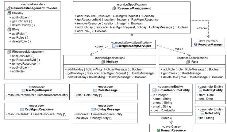
Figure 9 shows the refined specification for the IResourceManagement service. This service is a com- posite service (i.e. it uses other services to provide its functionality). The composite service specification (RscMgmtCompServSpec) implements the service specifi- cation and uses the two services IHoliday and IRole. The service specifications of the three services now contain in- formation about parameters. In addition, messages for ser- vice communication and parameter types (*Entity) for these messages have been defined. For the HumanResourceEn- tity, the parameter type has been derived from legacy code.
In addition, the services are composed in this phase.
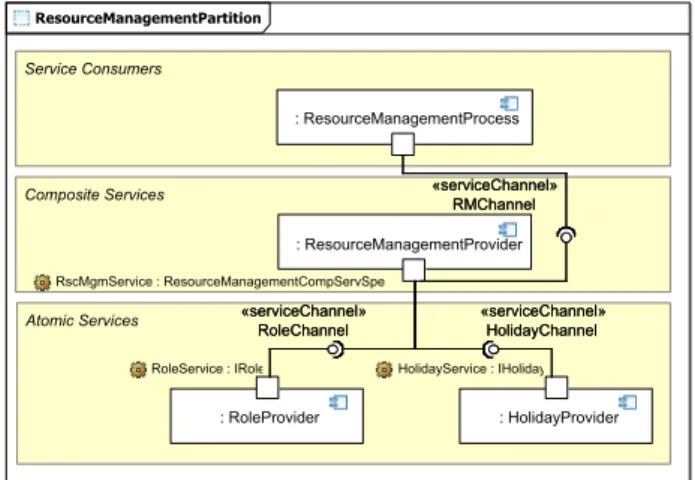
Figure 10 shows the composition of the IResourceMan- agement,IRoleandIHolidayservices. The upper part con- tains the service consumer which is the corresponding busi- ness process (ResourceMangementProcess). This consumer component will later use the functionality of theIResource- Management service. The IResourceManagement service is a composite service using theIRoleandIHolidayservices.
All components are connected by service channels which will later be used to send messages between the services.
At the end of this phase, the service design is mostly completed. The service specification now contains all ser- vice operations and their parameters. Messages and message parameter types have been specified. In addition, the compo-
sition of the services has been defined. The next step is now to decide how the services are implemented.
5.5 Service Realization
The first decision to be made during Service Realization is how to implement services. Model transformation ap- proaches are also suited for code transformation. Thus, the legacy code is transformed into a service implementation to provide the business functionality. If service realization by wrapping is decided, wrappers can be generated analo- gously.
Identifying which code is able to implement the business functionality of a service is one key challenge in migrating legacy systems towards SOAs. In this case study, two dif- ferent but complementary approaches are presented: static analysis and dynamic analysis.
5.5.1 Identifying Code by Static Analysis
For the core functionality of theIResourceManagementser- vice, Service Identification already identified one class in the legacy code that may provide functionality to the service: the HumanResourceManager class (short: HRM). Looking at the source code manually, this class seems to provide func- tionality to add, retrieve and delete resources. Therefore, this class is suited to implement one core part of the service.
Now, the complete but minimal code realizing this func- tionality has to be determined and transformed into exe- cutable code. Slicing these code fragments also requires to consider dependencies ofHRM.
Listing 6 describes the GReQL query retrieving these static dependencies. It returns a list of all classes and inter- faces thatHRM depends on. The path expressions in this query retrieve classes and interfaces needed with respect to the following dependencies:
– method invocations (line 8) – method parameters (line 9) – local variables (line 10) – return types (line 11) – fields (line 15)
– super classes or implemented interfaces (line 16) – member classes (line 17)
Such complex queries require an understanding of GReQL and a solid knowledge about the repository-schema. How- ever, once created, they can be reused in the remaining project.
While the GReQL query returns a set of qualified type- names, Figure 11 shows a (manually created) visualization of this query result. Using these classes to implement the service provides functionality to add, retrieve and remove resources.
Fig. 9 Detailed design of theIResourceManagementservice
1 from hrmClass : V{ C l a s s D e f i n i t i o n } ,
2 hrmMethod : V{ M e t h o d D e f i n i t i o n } ,
3 usedType : V{Type}
4 with
5 hrmClass . name = " HumanResourceManager " and hrmClass <−−{I s C l a s s B l o c k O f}<−−{IsMemberOf } hrmMethod and
6 (
7 hrmMethod (
8 (<−−{IsBodyOfMethod } <−−{IsStatementOfBody } (<−−{A t t r i b u t e d E d g e ,^ IsBreakTargetOf ,^
I s C o n t i n u e T a r g e t O f ,^ I s T y p e D e f i n i t i o n O f })∗ & { M e t h od I n v oc a t i on } <−−{
I s D e c l a r a t i o n O f I n v o k e d M e t h o d } & { M e t h o d D e f i n i t i o n } −−>{IsMemberOf } −−>{I s C l a s s B l o c k O f }) |
9 (<−−{IsParameterOfMethod } <−−{IsTypeOf}+ <−−{I s T y p e D e f i n i t i o n O f }) |
10 (<−−{IsBodyOfMethod } <−−{IsStatementOfBody } (<−−{A t t r i b u t e d E d g e ,^ IsBreakTargetOf ,^
I s C o n t i n u e T a r g e t O f ,^ I s T y p e D e f i n i t i o n O f })∗ <−−{I s T y p e O f V a r i a b l e } <−−{I s T y p e D e f i n i t i o n O f ) |
11 (<−−{IsReturnTypeOf } <−−{I s T y p e D e f i n i t i o n O f }) )
12 usedType
13 or
14 hrmClass (
15 (<−−{ I s C l a s s B l o c k O f } <−−{IsMemberOf } <−−{I s F i e l d C r e a t i o n O f } <−−{I s T y p e O f V a r i a b l e } <−−{ I s T y p e D e f i n i t i o n O f } ) |
16 ((<−−{ I s S u p e r C l a s s O f C l a s s } | <−−{I s I n t e r f a c e O f C l a s s }) <−−{I s T y p e D e f i n i t i o n O f }) |
17 ((<−−{ I s C l a s s B l o c k O f } <−−{IsMemberOf })+))
18 usedType
19 )
20 rep or t S et theElement ( usedType <−−& { I d e n t i f i e r }) . name end Listing 6 GReQL query retrieving dependencies
Fig. 10 Composition of the three services
5.5.2 Identifying Code by Dynamic Analysis
In addition to adding, retrieving and removing resources, the IResourceManagementservice also provides operations to add roles and holidays. This functionality is provided by the IRoleandIHolidayservices. Both services need legacy code to implement the business functionality, too. In this example, a dynamic approach is used to map legacy code to these two services.
The dynamic analysis set-up described in Section 4.3 is used to identify legacy code that is able to implement each of the three services. The dynamic analysis had already been executed during Service Identification (cf. Section 5.3.2).
Now, the tracing information that had been derived from the log files and stored to the repository is processed by further analysis techniques to identify code to implement the ser- vices according to exemplary runs of GanttProject. In this example, it is computed for each class how often a method of this class is called in each business process step. Each class is allocated to the process in which its methods are called most often.
Table 1 shows classes and their mapping to a process after filtering out GUI classes (e.g. panels, actions or ren- derer). The business process column names the process step in which a method of the class was called most often.
The significance value (Sig.) is the percentage how often a method of the class was called in this process in contrast to all calls. The three remaining columns (#Resource, #Holi- day and #Role) stand for the total number of occurrences in each process.
The values can be interpreted as follows: Classes with a high significance value (>0,5, marked bold in the table) can be allocated clearly to the named process as they are mostly used during the corresponding business process step.
So the classGanttDaysOis only used in theManageHoli- daybusiness process and should therefore be allocated to the IHolidayservice. Classes likeHumanResource,HumanRe-
sourceManagerandProjectResourceare called most often in theManage Resourceprocess and should be allocated to theIResourceManagementservice (that matches the result of the static analysis in Section 5.5.1). In addition, theRole- ManagerImplclass should be allocated to theIRoleservice.
However, some classes have quite low significance val- ues (≤ 0,5). They are used in each process similarly.
This indicates that these classes are some kind of helper classes used in all processes. In addition, the three classes with italic class names (RoleImpl,RoleManager.Accessand RoleSetImpl) seem to be mis-allocated. Their name suggests that they should be allocated to theIRole service. Instead, they are mapped to theIResourceManagementservice. As they are called in these two processes the same number of times, this is a hint that these both processes may not be separated well in the legacy code.
Taking the results of this analysis gives a first insight where to look in the legacy code to find a service imple- mentation. Manually exploring the legacy code confirms the results of the dynamic analysis. The classGanttDaysOis suited to implement the business functionality of theIHoli- dayservice and the classRoleManagerImplcan implement theIRoleservice.
5.5.3 Integrating Business Functionality into Service Design
Summarizing, the static and dynamic analyses gave useful hints to developers where to look in the legacy system to find code that is able to implement the business functionality of the three services. Next, the business functionality must be integrated into the overall service design. This is done according to the patterns proposed by Wahli (Wahli 2007).
Figure 12 shows the application of these patterns to cre- ate a framework to integrate the legacy code which will be transformed in the next phase. Theservice componentRe- sourceManagerSCimplements the service specification. A facade pattern is used to implement the service component.
The facade class delegates service requests to the appropri- ate service implementation, in this example theHRMclass, and all its dependencies revealed by the GReQL query. The IRoleandIHolidayservices are designed in a similar man- ner.
After accomplishing this phase, the service design con- tains a complete specification about how to implement the services by legacy code. The next step is to implement this design and to transform the legacy code into a service im- plementation.
5.6 Service Implementation
During Service Implementation, the services are imple- mented, e. g. as Web Services (as is supposed by SOMA).
«Java Interface»
ResourceManager
«Java Class»
HumanResourceManager
«Java Class»
ProjectResource
«Java Class»
GanttDaysOff
«Java Interface»
CustomPropertyManager
«Java Class»
GanttCalendar
«Java Class»
PropertyTypeEncoder
«Java Interface»
CustomProperty
«Java Interface»
Role
«Java Interface»
CustomPropertyDefinition
«Java Interface»
GPUndoManager
«Java Class»
CustomPropertyDefinitionImpl
«Java Class»
ResourceEvent
«Java Class»
HumanResource
«Java Interface»
ResourceView
«use»
«use»
«use»
«use»
«use»
«use»
«use»
«use»
«use»
«use»
«use»
«use»
«use»
«use»
«use»
Fig. 11 Service Realization: Dependencies ofHRMclass
Qualified Class Name Business Process Sig. #Resource #Holiday #Role
net.sourceforge.ganttproject.calendar.GanttDaysOff ManageHoliday 1,00 0 2 0
net.sourceforge.ganttproject.language.GanttLanguage ManageHoliday 0,39 5 7 6
net.sourceforge.ganttproject.resource.LoadDistribution ManageHoliday 0,46 4 6 3
net.sourceforge.ganttproject.resource.LoadDistribution.Load ManageHoliday 1,00 0 1 0
net.sourceforge.ganttproject.resource.HumanResource ManageResource 0,86 19 2 1
net.sourceforge.ganttproject.resource.HumanResourceManager ManageResource 0,73 11 3 1
net.sourceforge.ganttproject.resource.ProjectResource ManageResource 0,63 12 4 3
net.sourceforge.ganttproject.resource.ResourceColumn ManageResource 0,40 2 2 1
net.sourceforge.ganttproject.resource.ResourceEvent ManageResource 0,50 1 1 0
net.sourceforge.ganttproject.resource.ResourceNode ManageResource 0,38 5 4 4
net.sourceforge.ganttproject.roles.RoleImpl ManageResource 0,40 4 4 2
net.sourceforge.ganttproject.roles.RoleManager.Access ManageResource 0,33 1 1 1
net.sourceforge.ganttproject.roles.RoleSetImpl ManageResource 0,38 5 4 4
net.sourceforge.ganttproject.roles.RoleManagerImpl ManageRole 0,64 2 3 9
Table 1 Result of dynamic analysis
Fig. 12 Implementation design ofIResourceManagementservice
Migrating identified source code (cf. Section 5.5) to realize the three services combines functionality provided by the IBM Rational Software Architect for WebSphere Software V7.5.43(RSA) and TGraph technology.
First, the code generation capabilities of the RSA are used to create WSDL code (interface description language for Web Services) from the service specifications. WSDL is later used to specify the service interfaces. Next, the design of the service framework (UML diagram in Figure 12 which includes service component, facade pattern and facade inter- face) are transformed into Java.
So far, the service implementation lacks of business functionality, which will be added by transforming legacy code into a service implementation. The GReQL query de- scribed in Listing 6 (Section 5.5) is used to mark theHRM
3 IBM, Rational and WebSphere are trademarks of International Business Machines Corporation.