Research Collection
Journal Article
Interface strength and mechanical properties of Inconel 718 processed sequentially by casting, milling, and direct metal deposition
Author(s):
Soffel, Fabian; Eisenbarth, Daniel; Hosseini, Ehsan; Wegener, Konrad Publication Date:
2021-05
Permanent Link:
https://doi.org/10.3929/ethz-b-000460894
Originally published in:
Journal of Materials Processing Technology 291, http://doi.org/10.1016/j.jmatprotec.2020.117021
Rights / License:
Creative Commons Attribution-NonCommercial-NoDerivatives 4.0 International
This page was generated automatically upon download from the ETH Zurich Research Collection. For more information please consult the Terms of use.
ETH Library
Journal of Materials Processing Tech. 291 (2021) 117021
Available online 18 December 2020
0924-0136/© 2020 The Authors. Published by Elsevier B.V. This is an open access article under the CC BY-NC-ND license
(http://creativecommons.org/licenses/by-nc-nd/4.0/).
Interface strength and mechanical properties of Inconel 718 processed sequentially by casting, milling, and direct metal deposition
F. Soffel
a,*, D. Eisenbarth
a, E. Hosseini
b, K. Wegener
cainspire AG, Technoparkstrasse 1, 8005, Zürich, Switzerland
bEmpa Swiss Federal Laboratories for Materials Science & Technology, Überlandstrasse 129, 8600, Dübendorf, Switzerland
cInstitute of Machine Tools and Manufacturing, ETH Zürich, Leonhardstrasse 21, 8092, Zürich, Switzerland
A R T I C L E I N F O Associate Editor: Feng Lin Keywords:
Direct metal deposition Hybrid manufacturing Process chain Tensile properties Inconel
A B S T R A C T
Inconel 718 is the most commonly used nickel-based superalloy, mainly because it exhibits good weldability and can be processed by various types of manufacturing technologies. The combination of these processes with AM, typically referred to as hybrid manufacturing, can overcome limitations that exist in conventional process chains.
However, different cooling rates of the material during hybrid manufacturing cause local variations in micro- structure and mechanical properties within the components. Thus, quantification of the impact of individual process steps on the resulting properties could reveal most suitable process combinations. The present study focuses on the fabrication and repair of parts by casting, interface milling, and direct metal deposition (DMD).
Four processing routes are investigated where heat treatment and interface conditions are varied before applying the DMD process. The cast components are either solution annealed or without heat treatment, and the interface to the DMD part remains either as-cast or it is milled. The results show that all conditions allow dense bonding between the cast section and the additively manufactured structure. The tensile properties of the test specimens exceed the level of conventionally cast parts and can be predicted by numerical simulation. The proposed combination of casting, milling, and DMD may therefore be applied to hybrid manufacturing process chains to increase the level of material efficiency and design flexibility.
1. Introduction
Nickel-based superalloys are widely used in the energy and aero- space industries. Inconel 718 accounts for a significant percentage of the weight of modern aeronautical engines, as it is a preferred material for forged discs, cast blades, and housings (Arunachalam and Mannan, 2000). The sluggish precipitation kinetics of the γ’’ strengthening phase in this alloy reduces susceptibility to several modes of cracking during and after welding operations (DuPont et al., 2009), which qualifies Inconel 718 for both repair welds and welded assemblies. The repair of cast turbine blades is a typical application for the combination of direct metal deposition and milling, as the high precision and stability of laser welding offers various possibilities for process automation and quality assurance (Yilmaz et al., 2010). Therefore, modern processing systems that allow both laser-based additive manufacturing and milling on the same working table with a shared coordinate system can furthermore become attractive for the fabrication of new complex parts. In this case, the utilization of cast or forged preforms as substrates within new
process chains can significantly increase the overall productivity.
Hybrid additive manufacturing of new parts typically involves laser deposition welding processes in combination with milling. For this purpose, several machine tool manufacturers have integrated laser processing equipment into 5-axis CNC machines (Cortina et al., 2018b).
The main advantage of such an integration is the capability to deposit material on free-form surfaces and to perform machining operations within the same clamping system. To increase process efficiency, Chen and Frank (2019) suggested the basic part shape can be obtained with conventional manufacturing methods. Complex or difficult to machine features can be subsequently added by AM. Stastny et al. (2016) describe a procedure to add heat-extracting features on cast turbine engine components. Polenz et al. (2019) generated local stiffening ribs by DMD on cast engine supports and found that the tensile properties of hybrid tensile specimens are within the requirements of the automotive in- dustry. For combined processing chains, mutual influences between the individual process steps need to be considered. Cortina et al. (2018a) showed that residual cutting fluid on milled surfaces could increase the
* Corresponding author.
E-mail address: soffel@inspire.ethz.ch (F. Soffel).
Contents lists available at ScienceDirect
Journal of Materials Processing Tech.
journal homepage: www.elsevier.com/locate/jmatprotec
https://doi.org/10.1016/j.jmatprotec.2020.117021
Received 31 July 2020; Received in revised form 11 December 2020; Accepted 13 December 2020
Journal of Materials Processing Tech. 291 (2021) 117021
2 risk for porosity formation at the interface to the following DMD segment. It is therefore advantageous to perform a cleaning step be- tween milling and DMD. Features with limited accessibility may require multiple alternating DMD and milling process steps. Eisenbarth et al.
(2019a) demonstrated that DMD protrusions can protect the previously milled and eventually no longer accessible surfaces and allow smooth transitions between the individual sections.
Part repair has been accomplished for various applications by com- bined processing. Flynn et al. (2016) describes that for several hybrid AM machine manufacturers, the repair of high-value parts is actually the main focus. Yu et al. (2018) compared gas metal arc welding and DMD for the repair of morphological defects in gray cast iron and found that the heat affected zone in the part was 21 times smaller with DMD.
Praniewicz et al. (2018) presented an additive/subtractive strategy for the repair of turbine blades and could reduce machining time by nearly 18 % with an adaptive geometry transformation approach. Liu et al.
(2014) investigated DMD as a repair process for machined blind and through holes in cast Inconel 718 parts and showed that inclined groove surfaces pose an increased risk for lack of fusion. They achieved defect-free transitions from the cast to the welded section with opti- mized parameters. However, their proposed process chain included an intermediate sand-blasting step that could be skipped to increase process efficiency. To qualify hybrid additive manufacturing for part fabrication or repair, it is important to ensure that the required mechanical prop- erties can be achieved. Mechanical strength of nickel-based superalloys is significantly influenced by grain morphology and precipitate forma- tion (Pollock and Tin, 2006). The fine microstructure in AM material typically causes higher hardness and tensile strength in the as-built condition compared to as-cast parts (Hosseini and Popovich, 2019).
However, AM defects or undesirable phases can deteriorate the mate- rial’s strength, which might prevent the application of hybrid AM for structural components. As an example, Zhang et al. (2020) found that under static tensile load hot-rolled Inconel 718 repaired by DMD pref- erably fractured in the repair zone at the Laves phase precipitates. For the development of combined manufacturing sequences, it is therefore of high interest to study the influences of individual process steps on microstructure evolution and mechanical properties.
The main aim of the present study is to investigate promising process chains for part fabrication and repair by casting, interface milling, and direct metal deposition. The microstructure and tensile properties of specimens fabricated by four processing routes with different heat treatment and interface conditions were investigated. A groove repair case was selected to determine the risk for lack of fusion formation on the inclined groove surfaces. In summary, for all tested heat treatment and interface conditions the proposed sequences resulted in higher tensile strengths compared to conventionally cast parts. The paper is structured as follows: Section 2 summarizes the test specimen produc- tion and describes the methods for microstructure analysis and tensile testing. Section 3 presents and discusses the results of the metallo- graphic interface investigations and tensile properties. Finally, Section 4 provides conclusions of the relevant findings.
2. Materials and methods 2.1. Specimen manufacturing
The nickel-based superalloy Inconel 718 was selected to investigate four process sequences that combine casting, milling, and DMD. Table 1 details the investigated sequences and reference conditions. Investment cast cylinders with a diameter of 26 mm and a height of 100 mm were manufactured at GF Precicast. For sequence 2 and 4, the cylinders were solution annealed for two hours at 1100 ◦C. Sand-blasting was applied to the specimens in both as-cast and solution annealed condition to obtain a smooth surface. A 5-axis combined milling machine GF HPM 450 U with a retrofitted laser processing system was used for interface pro- cessing and additive manufacturing. The machine tool has three linear axes, X, Y, and Z, and two rotary axes, B and C, which allows both 5-axis machining and laser deposition. For interface processing of sequence 3 and 4 the cast cylinders were clamped and the top surface was face- milled. As a milling tool for this process step, a corner radius end mill with 6 mm of diameter was used. Additive manufacturing of the DMD structures was performed with the integrated laser processing system Ambit S5 that includes an IPG fiber laser and an Ambit cladding head.
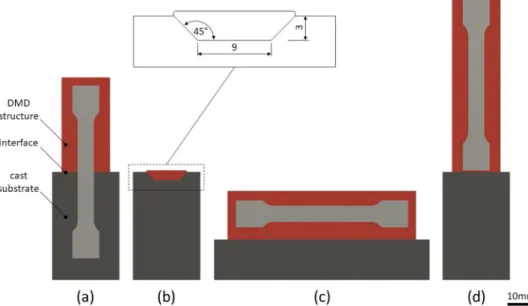
The theoretical spot size of the laser is 3 mm and the resulting melt pool width approximately 2.2 mm. Argon is used as shielding, nozzle pro- tection, and powder carrier gas at flow rates of 8 L/min, 4 L/min, and 4 L/min, respectively. On top of the cast parts, three cylindrical DMD structures were deposited per built job. The cylinders had a diameter of 20 mm, a height of 35 mm for the half cast / half DMD specimens (Fig. 1a), and a height of 65 mm for the vertical DMD reference speci- mens (Fig. 1d). To investigate the effect of the building direction on tensile properties, horizontal DMD reference specimens were produced with rectangular DMD structures with a length of 75 mm, width of 20 mm, and a height of 21 mm (Fig. 1c). As powder material, Inconel 718 from LPW Technology Ltd. with a particle size distribution from 44 to 105 μm was used at a flow rate of 4.1 g/min. The chemical composition of the powder is detailed in Table 2. A raster/contour scanning strategy was implemented with a raster scan speed of 333 mm/min and a contour scan speed of 200 mm/min. The raster orientation was rotated by 45◦for each following layer. The initial laser power of 1000 W was reduced to a minimum power of 725 W in the upper layers by a model-based feed forward approach as described previously by Eisenbarth et al. (2019b).
In this approach, an algorithm within the CAM software correlates experimentally determined process parameters to a local geometric factor to ensure comparable melt pool properties. Tensile test specimens were extracted from the cast cylinders and DMD structures as illustrated in Fig. 1.
Process sequence 4 was chosen to demonstrate the feasibility of sequential processing for a repair application. A volumetric part defect, such as a ceramic inclusion or a misplaced drilling hole, is simulated and a groove is machined to remove all material around the defect by milling. Besides drying and cleaning the groove for coolant removal, no further interface processing was performed to avoid reclamping of the workpiece. The 3 mm deep milled groove with a wall angle of 45 degrees as illustrated in Fig. 1b was filled with the deposition strategy described above with four layers. The milled grooves bottom width was 9 mm and Table 1
Process sequences for the manufacturing of half cast / half DMD specimens (1-4) and reference specimens (5-8).
sequence primary forming heat treatment interface processing additive manufacturing acronym
1 investment casting none sand-blasting DMD cast +DMD
2 investment casting annealed sand-blasting DMD cast HT +DMD
3 investment casting none milled DMD cast M +DMD
4 investment casting annealed milled DMD cast HT M +DMD
5 investment casting none – – cast (reference)
6 investment casting annealed – – cast HT (reference)
7 – – – DMD DMD vertical (reference)
8 – – – DMD DMD horizontal (reference)
F. Soffel et al.
the bottom length 14 mm.
2.2. Tensile tests and modelling
The round tensile specimens with M10 threads had a gauge length of 30 mm and a diameter of 6 mm. For each process sequence and reference condition three tensile tests were carried out at room temperature ac- cording to EN ISO 6892-1 (type B) on a Zwick Z050. The testing speed was 1 mm/min in the elastic region and increased to 10 mm/min after 0.5 % of plastic elongation. Based on the observations from tensile testing of the cast, cast HT, and DMD vertical reference specimens three material models were derived and implemented in ANSYS Mechanical 2019 R3. The crosshead displacement of the tensile testing machine was simulated with a fixed support at the specimen bottom and a continuous displacement at the top to predict the tensile properties of half cast / half DMD specimens at room temperature.
2.3. Microstructure analysis
For microstructural analysis one groove specimen and one tensile specimen each from process sequence 1–4 after tensile testing were sectioned along the building direction. The cross sections were ground flat with SiC papers from 240 to 4000 and polished with 3 μm and 1 μm diamond paste. In polished condition, porosity was determined from four DMD sections by image analysis within the software ImageJ. Kal- ling II was used as an etchant to reveal the microstructure. The interfaces between cast and DMD sections were analyzed by optical microscopy for possible defects and grain morphologies. Vickers hardness measure- ments with a load of 29.4 N (HV3) were performed on one selected specimen with a Qness Q10 M testing device. EBSD analysis for grain size determination was conducted with a Digiview V camera from EDAX within a Tescan Mira scanning electron microscope and ATEX data analysis software.
3. Results and discussion
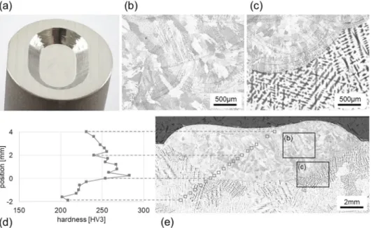
Fig. 2 shows the microstructural analysis results of the groove repair specimen, which was fabricated with process sequence 4. The DMD process of the 3 mm deep groove with an initially milled surface leads to a smooth interface without lack of fusion. This absence of bonding de- fects is essential for the mechanical integrity of AM parts, as the irregular geometries of such defects act as stress concentrators, which may dete- riorate the material’s strength. The differences in microstructure are apparent from Fig. 2c: from coarse dendritic with primary dendrite arm spacings of approximately 100–130 μm in the cast section to a very fine microstructure within the DMD filling. For both cast and DMD material, the highest hardness values as illustrated in Fig. 2d are obtained near the interface. In the cast section the average hardness is 218 HV. Above the interface, there is an approximately 300− 400 μm thick DMD region that is especially fine-grained and where hardness reached 283 HV. This can be explained with the fastest heat dissipation during the deposition of the first layer. In the upper regions, increased part temperature and in- situ heat treatment lead to a coarser microstructure with a mean hard- ness of 245 HV in a region 2–4 mm above the interface, compared to 265 HV in the lower region (Table 3). The hardness measurement results of the DMD material are in agreement with previous studies. Zhang et al.
(2017) used comparable process parameters and reported a hardness of 252 HV. With a smaller laser spot diameter of 1.0 mm, Zhang et al.
(2011) measured a hardness of about 300 HV. These findings support the conclusion that for Inconel 718 processed with AM, the dominant contributor to the material’s hardness is grain boundary strengthening, which is increased for smaller grain sizes.
The EBSD image of the interface region is shown in Fig. 3. The finest grains are allocated in the lower 300 μm of the first layer of the DMD structure. In the middle and upper regions of this layer larger grains have formed due to decreased cooling rates. The average grain sizes determined by the sections in Fig. 4 are 43 μm in the DMD material and 1584 μm in the cast area.
Fig. 5 illustrates the location of vertically extracted tensile test Fig. 1. Test specimen geometries for (a) half cast / half DMD, (b) groove repair, (c) horizontal and (d) vertical DMD reference specimens and location of extracted tensile test bars.
Table 2
Chemical composition of the Inconel 718 powder.
Element Fe Ni Cr Nb +Ta Mo Ti Al C N O
wt.% Bal. 53.02 18.99 5.11 3.0 0.95 0.49 0.04 0.02 0.01
Journal of Materials Processing Tech. 291 (2021) 117021
4
Fig. 2.(a) Groove repair specimen after machining, (b) DMD microstructure, (c) interface area, (d) hardness profile, and (e) cross-section overview with locations of hardness indentations.
Table 3
Average hardness (HV3) of cast and DMD specimens and literature references.
Mean values and standard deviations from this study are based on six mea- surements for each section.
HV
DMD upper section, 2.0−4.0 mm above interface 245 ±9 lower section, 0.3− 1.7 mm above interface 265 ±11 literature review (Hosseini and Popovich, 2019) 255 ±17
cast 0.3− 1.9 mm below interface 218 ±10
literature review (Hosseini and Popovich, 2019) 223 ±16
Fig. 3. EBSD analysis of the interface area with coarse grains in the lower cast section and fine grains within the first deposited layer on top.
Fig. 4.EBSD analysis for determination of the average grain size d in the (a) DMD and (b) cast section.
F. Soffel et al.
specimens. The cast-only and DMD-only specimens (Fig. 5a and b) were manufactured as references. The half cast / half DMD specimens (Fig. 5c) originate from four process sequences as described in Table 1.
The DMD structures have a rather matte surface, which is an indicator for oxidation. Most hybrid DMD machine tools operate with local shielding gas flow and do not possess hermetically sealed chambers, such that oxidations may occur from insufficient shielding of the deposited structures. Additionally to some spatter particles on the as- built cylinders, a helical-shaped line indicates the start and end points of each laser contour path. The surface roughness in the as-built con- dition is clearly visible from the individual laser tracks. As shown by DebRoy et al. (2019), post-processing can be the dominant contributor to the cost of AM parts. Whereas in gas metal arc welding the surface roughness of AM structures is several hundred micrometers or more (Nagamatsu et al., 2020), it can be orders of magnitude lower for DMD processes. This makes DMD attractive for applications that require milling for surface finishing. Especially for difficult to machine mate- rials, such as titanium or nickel-based superalloys, the comparably good DMD surfaces allow for small stock removal, which reduces the costs for post-processing.
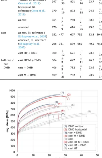
Table 4 summarizes the tensile testing results. The DMD reference specimens exhibited the highest yield strength (YS) and ultimate tensile strength (UTS) with a slight effect of specimen orientation. Vertical specimens with the tensile load applied parallel to the building direction have an average YS of 520 MPa, UTS of 932 MPa, and an elongation at fracture (A) of 28 %. Horizontal specimens show a 3 % lower UTS value but a 7 % and 6 % increase in yield strength and elongation, respec- tively. Compared to the anisotropy of DMD material observed by Ostra et al. (2019), the results of the present study show a different behavior.
Therefore, there seems to be an effect of process parameters on the resulting anisotropy of DMD material. Lowest strengths but largest ductility were achieved by the solution-annealed cast reference condi- tion. As-cast specimens have an ultimate tensile strength of 750 MPa and a yield strength of 354 MPa, which is 24 % and 47 % lower than for the DMD reference. As indicated by Hosseini and Popovich (2019), such differences in strength of cast and AM material are typically related to larger grains within cast parts. The coarse-grained microstructure orig- inates from lower cooling rates during casting and results in a smaller amount of grain boundary strengthening and reduces the material’s
strength according to the Hall-Petch equation.
As illustrated in Fig. 6, the half cast / half DMD specimens from all four processing routes experience slightly higher ultimate tensile strength and yield strength than their cast references. Only one of these specimens broke near the DMD interface, whereas for 11 specimens the location of fracture was within the cast section. Thus, the interface be- tween the cast and the DMD material does not appear to be critical for part failure. There is no effect of the interface condition on YS, whereas UTS is 4 % larger for the heat-treated and machined specimens, but 4 % lower for the as-cast and machined specimens, compared to the sand- blasted interface condition. These results show that all four analyzed process sequences are suitable for part fabrication or repair, indepen- dent of the selected interface processing step. Compared to the cast and DMD reference conditions, the half cast / half DMD specimens have a significantly lower elongation at fracture, which is because plastic deformation of these specimens occurs almost exclusively on the cast Fig. 5. Locations of extracted tensile test specimens from (a) cast-only, (b)
vertical DMD-only, and (c) half cast / half DMD specimens.
Table 4
Yield strength (YS), ultimate tensile strength (UTS) and fracture elongation (A) of Inconel 718 specimens fabricated with different processes. Mean values and standard deviations from this study are based on three tensile test results for each condition.
YS [MPa] UTS [MPa] A [%]
DMD
vertical 520 ±
2 932 ±
5 27.6 ±
1.0
horizontal 561 ±
4 909 ±
1 31.3 ±
vertical, lit. reference ( 0.8
Ostra et al., 2019) 397 ±
30 801 ±
10 23.7 ±
horizontal, lit. 5.9 reference (Ostra et al.,
2019) 370 ±
19 873 ±
18 24.8 ±
2.2
cast
as-cast 354 ±
7 750 ±
2 32.5 ±
1.0
annealed 276 ±
9 616 ±
25 45.0 ±
as-cast, lit. reference ( 3.4
El-Bagoury et al., 2005) 352 - 477 607 - 752 33.8 - 39.4 annealed, lit. reference
(El-Bagoury et al.,
2005) 268 - 311 539 - 682 70.2 - 78.2
half cast / half DMD
cast HT +DMD 300 ±
12 621 ±
4 23.3 ±
3.6 cast HT M +DMD 304 ±
3 647 ±
11 26.3 ±
0.9
cast +DMD 406 ±
5 782 ±
2 23.6 ±
1.0
cast M +DMD 409 ±
21 752 ±
5 23.9 ±
1.4
Fig. 6. Eng. stress-strain curves of IN718 half cast / half DMD specimens and reference conditions.
Journal of Materials Processing Tech. 291 (2021) 117021
6 section. This phenomenon is visualized in Fig. 7, where the diameter in the interface region reduces from 5.8 to 5.0 mm. To avoid misunder- standing of different phases with volumetric defects, porosity and lack of fusion were analyzed on cross-sections before specimen etching in the polished condition. The transitions between the cast and the DMD sec- tions of the tensile specimens are smooth without any lack of fusion defects. The level of porosity in the DMD material is between 0.01 % and 0.04 % with a typical pore diameter of 20− 30 μm.
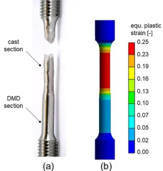
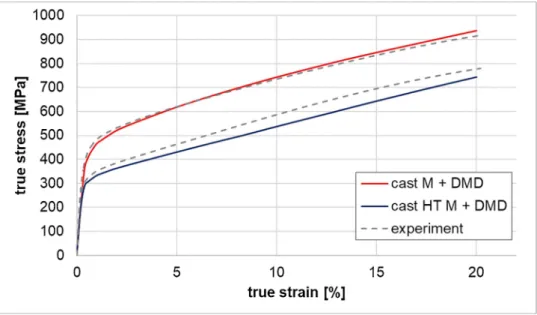
Table 5 shows the multilinear isotropic hardening model inputs derived from the tensile test results of the reference specimens. With these inputs, the mechanical response of the half cast / half DMD con- dition is predicted in ANSYS Mechanical under quasi-static tensile load with an average edge length of 0.5 mm of the mesh. The plastic defor- mation illustrated in Fig. 8 occurs mainly in the cast section. As the initial diameter in the cast material decreases, the local normal stress increases which explains why in the experimental study the fracture position for the majority of specimens is within the cast section. In Fig. 9, the predicted stress-strain curves for “cast HT M +DMD” and “cast M + DMD” conditions are plotted with the experimental results. The model errors of the predicted normal stress are less than 5 % for the “cast M + DMD” condition and up to 10 % for “cast HT M +DMD” specimens where the cast cylinders were solution annealed before interface pro- cessing and DMD.
There are two main limitations in the present study. First, many in- dustrial applications will require precipitation hardening as a final heat treatment of the components, which was not analyzed in this study.
Second, the mechanical properties were only determined under static tensile load at room temperature. Considering these limitations, the findings of this study may be regarded as an initial investigation of possible process chains.
Overall, the experimental results confirm the potential of the inves- tigated process combinations for hybrid additive manufacturing. Since the material’s strength in the transition zone exceeds the level of cast parts in all sequences, part fabrication and repair becomes more flexible on hybrid AM machine tools. This improved flexibility can lead to an increase of process efficiency and reveals new design possibilities for future applications.
4. Conclusions
The present study evaluates four processing sequences for hybrid additive manufacturing that combine casting, milling, and DMD. The results confirm that the investigated sequences are feasible for Inconel 718 part production and repair. Possible applications might include the addition of complex features on cast parts and the repair of high-value components. The following conclusions are relevant for this work and future research:
• The sequentially processed Inconel 718 specimens show smooth transitions from the cast section to the DMD material without lack of fusion defects. The tensile properties of specimens extracted from the transition zone (YSmax =409 MPa and UTSmax =782 MPa) exceed the level of as-cast material (YS =354 MPa and UTS =750 MPa). Fracture elongation is reduced from 32 % in the as-cast condition to 24 % in the interface zone, as plastic deformation occurs mainly in the cast section. The fracture location of 11 from total 12 interface specimens is within the cast section. Therefore, the milled or sand-blasted interface condition of DMD structures on as-cast or solution- annealed Inconel 718 is not critical for part damage under static tensile load.
Fig. 7. Polished cross-section of a half cast / half DMD tensile specimen and extraction location.
Table 5
Multilinear isotropic hardening model inputs derived from reference tensile tests.
cast HT strain [-] 0 0.0030 0.0115 0.0265 0.0574 0.1269 0.1866 0.2458 0.3019 0.3838
stress [MPa] 273 300.1 332.9 359.4 401.4 501.1 599.1 702.9 800.4 920.8
cast strain [-] 0 0.0012 0.0036 0.0088 0.0249 0.0718 0.1220 0.1734 0.2493
stress [MPa] 349 380.3 420.7 465.2 520.8 622.5 721.9 820.3 952.2
DMD strain [-] 0 0.0020 0.0045 0.0112 0.0212 0.0516 0.0916 0.1341 0.2133
stress [MPa] 521 567.2 602.4 653.9 701.1 799.3 902.6 1000.8 1153.5
Fig. 8. (a) Half cast / half DMD specimen after tensile test and (b) numerical prediction of equivalent plastic strain after 6 mm of crosshead displacement.
F. Soffel et al.
•The mechanical simulation performed in ANSYS can well predict tensile stress in the transition zone from both as-cast and solution- annealed sections to the DMD material.
•The tensile properties of DMD material are moderately anisotropic:
Horizontal specimens (YS =561 MPa, UTS =909 MPa, A =31 %) show +7.9 % yield strength, − 2.5 % ultimate tensile strength, and +10.7 % fracture elongation compared to the vertical test specimens (YS =520 MPa, UTS =932 MPa, A =28 %), which were extracted parallel to the building direction. With these results, the DMD ma- terial significantly exceeds the tensile strength properties of as-cast material with comparable ductility (YS =354 MPa, UTS =750 MPa, A =32 %).
•Future work will focus on optimized heat treatment sequences of Inconel 718 that include precipitation hardening to obtain final mechanical properties of hybrid AM parts. Additionally, high tem- perature mechanical testing under static and dynamic conditions will be considered for future investigations.
Declaration of Competing Interest
The authors declare that they have no known competing financial interests or personal relationships that could have appeared to influence the work reported in this paper
Acknowledgements
The authors would like to acknowledge the contribution of the funding agency Innosuisse (grant number 25498) and of the companies GF Machining Solutions, GF Precicast, and ABB Schweiz AG, Turbo- charging. Furthermore, the authors would like to thank Albert Weber for the tensile specimen machining, Knut Krieger for the metallographic investigations, and Xiaolong Li and Jian Tang for the EBSD analysis.
References
Arunachalam, R., Mannan, M.A., 2000. Machinability of nickel-based high temperature alloys. Mach. Sci. Technol. 4, 127–168. https://doi.org/10.1080/
10940340008945703.
Chen, N., Frank, M., 2019. Process planning for hybrid additive and subtractive manufacturing to integrate machining and directed energy deposition. Procedia Manuf. 34, 205–213. https://doi.org/10.1016/j.promfg.2019.06.140.
Cortina, M., Arrizubieta, J.I., Ukar, E., Lamikiz, A., 2018a. Analysis of the influence of the use of cutting fluid in hybrid processes of machining and laser metal deposition (LMD). Coatings 8 (2), 61. https://doi.org/10.3390/coatings8020061.
Cortina, M., Arrizubieta, J.I., Ruiz, J.E., Ukar, E., Lamikiz, A., 2018b. Latest developments in industrial hybrid machine tools that combine additive and subtractive operations. Materials 11 (12), 2583. https://doi.org/10.3390/
ma11122583.
DebRoy, T., Mukherjee, T., Milewski, J.O., Elmer, J.W., Ribic, B., Blecher, J.J., Zhang, W., 2019. Scientific, technological and economic issues in metal printing and their solutions. Nat. Mater. 18, 1026–1032. https://doi.org/10.1038/s41563-019- 0408-2.
DuPont, J.N., Lippold, J.C., Kiser, S.D., 2009. Welding Metallurgy and Weldability of Nickel-Base Alloys. John Wiley & Sons, Hoboken, pp. 237–242. https://doi.org/
10.1002/9780470500262.
Eisenbarth, D., Breuch, M., Soffel, F., Wegener, K., 2019a. Challenges of combining direct metal deposition with milling for the fabrication of a rocket nozzle. Proceedings of the Special Interest Group Meeting on Advancing Precision in Additive
Manufacturing, Nantes, France 83–86.
Eisenbarth, D., Soffel, F., Wegener, K., 2019b. Geometry-based process adaption to fabricate parts with varying wall thickness by direct metal deposition. In:
Almeida, H.A., Vasco, J.C. (Eds.), Progress in Digital and Physical Manufacturing, Proceedings of ProDPM’19. Leiria, Portugal, pp. 125–130. https://doi.org/10.1007/
978-3-030-29041-2_16.
El-Bagoury, N., Matsuba, T., Yamamoto, K., Miyahara, H., Ogi, K., 2005. Influence of heat treatment on the distribution of Ni2Nb and microsegregation in cast Inconel 718 alloy. Mater. Trans. 46, 2478–2483. https://doi.org/10.2320/
matertrans.46.2478.
Flynn, J.M., Shokrani, A., Newman, S.T., Dhokia, V., 2016. Hybrid additive and subtractive machine tools – research and industrial developments. Int. J. Mach.
Tools Manuf. 79–101. https://doi.org/10.1016/j.ijmachtools.2015.11.007.
Hosseini, E., Popovich, V.A., 2019. A review of mechanical properties of additively manufactured Inconel 718. Addit. Manuf. 30, 100877. https://doi.org/10.1016/j.
addma.2019.100877.
Liu, D., Lippold, J.C., Li, J., Rohklin, S.R., Vollbrecht, J., Grylls, R., 2014. Laser engineered net shape (LENS) technology for the repair of Ni-base superalloy turbine components. Metall. Mater. Trans. A 45 (10), 4454–4469. https://doi.org/10.1007/
s11661-014-2397-8.
Nagamatsu, H., Sasahara, H., Mitsutake, Y., Hamamoto, T., 2020. Development of a cooperative system for wire and arc additive manufacturing and machining. Addit.
Manuf. 31, 100896. https://doi.org/10.1016/j.addma.2019.100896.
Ostra, T., Alonso, U., Veiga, F., Ortiz, M., Ramiro, P., Alberdi, A., 2019. Analysis of the machining process of Inconel 718 parts manufactured by laser metal deposition.
Materials 12 (13), 2159. https://doi.org/10.3390/ma12132159.
Polenz, S., Oettel, M., L´opez, E., Leyens, C., 2019. Hybrid process chain from die casting and additive manufacturing. Lightweight des. worldw. 12, 44–49. https://doi.org/
10.1007/s41777-019-0021-8.
Pollock, T., Tin, S., 2006. Nickel-based superalloys for advanced turbine engines:
chemistry, microstructure and properties. J. Propul. Power 22 (2), 361–374. https://
doi.org/10.2514/1.18239.
Praniewicz, M., Kurfess, T., Saldana, C., 2018. An adaptive geometry transformation and repair method for hybrid manufacturing. J. Manuf. Sci. Eng. 141 (1), 011006.
https://doi.org/10.1115/1.4041570.
Stastny, H., Richard, F., Cote, M., 2016. Production of turbine components with heat- extractive features using additive manufacturing. Patent appl. US20160109130A1.
Yilmaz, O., Gindy, N., Gao, J., 2010. A repair and overhaul methodology for aeroengine components. Rob. Cim-Int. Manuf. 26 (2), 190–201. https://doi.org/10.1016/j.
rcim.2009.07.001.
Fig. 9.Stress-strain curves predicted by mechanical modelling compared to experimental results.
Journal of Materials Processing Tech. 291 (2021) 117021
8 Yu, J.-H., Choi, Y.-S., Shim, D.-S., Park, S.-H., 2018. Repairing casting part using laser
assisted additive metal-layer deposition and its mechanical properties. Opt. Laser Technol. 106, 87–93. https://doi.org/10.1016/j.optlastec.2018.04.007.
Zhang, Q.-l., Yao, J.-h., Mazumder, J., 2011. Laser direct metal deposition technology and microstructure and composition segregation of Inconel 718 superalloy. J. Iron Steel Res. Int. 18, 73–78. https://doi.org/10.1016/S1006-706X(11)60054-X.
Zhang, Y., Yang, L., Chen, T., Zhang, W., Huang, X., Dai, J., 2017. Investigation on the optimized heat treatment procedure for laser fabricated IN718 alloy. Opt. Laser Technol. 97, 172–179. https://doi.org/10.1016/j.optlastec.2017.06.027.
Zhang, Q., Zhang, J., Zhuang, Y., Lu, J., Yao, J., 2020. Hot corrosion and mechanical performance of repaired inconel 718 components via laser additive manufacturing.
Materials 13 (9), 2128. https://doi.org/10.3390/ma13092128.
F. Soffel et al.