Computer Architecture II:
Memory Management
M.A. Hillebrand, D.C. Leinenbach, W.J. Paul 20 May 2003 — 13 June 2003
1 Introduction
20 May 2003 second half Memory management deals with techniques (cheap and efficient!) to provide
user programs with sufficient memory especially in a multitasking environment.
We will treat a primitive implementation of virtual memory in which a user program can access a memory larger than the actual (physical) RAM; excessive parts are stored dynamically on hard-disc.
Memory management concerns both hardware and (operating system) soft- ware:
• A new piece of hardware is thememory management unit (MMU).
It has a medium-size, ugly specification.
• The MMU can cause exceptions, hence it interacts with the interrupt mechanism.
Interrupts mechanisms are ugly, see the start of chapter 5 of [MP00].
• One of the exceptions caused by the MMU is the page fault exception. It leads to the execution of thepage fault handler.
This piece of software is part of the operating system (OS).
• As far as theuser program is concerned, there are good things that should happen (simulation theorem) but also bad things that should not happen.
An unwanted interaction with respect to the user program is, that it should not destroy the operating system. This is a theorem about the impossibility of hacking. Hence, through the combination of the hardware mechanism and the operating system it must be guaranteed that no user program can destroy the operating system.
We have not yet done specifications of software and especially of the oper- ating system. In fact, such things have been only done for primitive example implementations. The general approach is the standard one:
• specify operating system components,
• implement these components,
• show that the implementation meets the specification (hierarchical cor- rectness).
For our lecture, we will do only parts of this. We will take the following simplified course of action:
• We specify
– the MMU and some additional hardware in the processor, – the OS software (initialization, page fault handlers) but only as far as memory management is concerned.
It will be nice and easy to show some desirable properties. The real problem lies in the (ugly) coordination of hardware and software.
• Then we construct the hardware and the software.
For the hardware part, again, this will be easy. However, to show cor- rectness for the software, we need, among other things, to show also the absence of interrupts. This is an open problem.
We now try to sketch the correctness theorem that we will prove for memory management; we call such a theorem “virtual memory simulation theorem”.
• The correct execution of the user program is formulated by introducing a new type of memory, the virtual memory (VM). The virtual memory is accessed by virtual address va∈ Va from the set of virtual addresses Va:={0, . . . ,232−1}. Each address stores a byte, hence a virtual memory configurationvmis a mapping from virtual addresses to bytes:
vm: [Va→ {0,1}8]
The user program accesses the virtual memory with the usual operations;
in an implementation, the user program should ‘see’ a uniform virtual memory.
• The difficulty arises from the fact that we do not build implement the virtual machine directly. Instead the implementation has two memories that hold the contents of the (user) virtual memory: the (physical) main memory and the swap memory. The main memory is implemented by RAM, it corresponds to the regular implementation memory. The swap memory is implemented as a special file / partition on hard-disc. It is used to store parts of the virtual memory that are not present in main memory.
We model both memories as functions mapping addresses to bytes. We have the set of main memory addressesMa ⊆ {0, . . . ,232−1} and the swap memory addressesSa ⊆ {0, . . . ,232−1}, which usually are astrict subset of all the implementable addresses (for cost reasons). With these sets, a main memory configurationmmand a swap memory configuration smmap addresses to bytes:
mm: [Ma→ {0,1}8] sm: [Sa→ {0,1}8]
Instruction I0 Ik+1 Il Il+1 Im Im+1 In In+1 Io
OS User
OS User
Ik
Initialisation Phase
Figure 1: Simulated User Program Execution on the Implementation
SM
a b
IMMU DMMU
PM I/O ICache
DCache fetch
load, store CPU
Figure 2: Overview of the hardware. At awe have to establish uniform virtual memory for the user (that means the MMUs are transparent). At b we have to establish uniform (regular) memory (that means the caches are transparent).
• When the user program is executed on such an implementation, it can only directly access the main memory. If it tries to access data that is not present in the main memory, an exception is caused. The page fault handler will fix the situation by copying data between the main and swap memory (I/O, slow). Then, the same user program instruction is repeated and hopefully also completed.
Hence, a computation of the implementation can be divided into phases.
At the start, the operating system initializes the system. Then, the op- erating system only takes over if the user program tries to access data not present in main memory. Hence, the user program and the operating system take turns in execution. Of course, in terms of execution efficiency, the less often the operating system is invoked, the better.
This situation is depicted in figure 1.
Data Consistency: Every instruction execution of the user program that does not cause a page-fault, must have the same effect, as if the same instruction would be executed on virtual memory.
Liveness: There must not occur page-faults indefinitely.
Figure 2 shows an overview of the hardware. Between the instruction and the data cache, there are two MMUs, the instruction MMU (IMMU) and the data MMU (DMMU). At mark a, the afore-mentioned virtual memory simu- lation theorem has to be established: when a user program executes, the MMU operation should be transparent to it, i.e. the user program should behave like it operates on a uniform virtual memory (ignoring the instructions executed by the operating system and the instructions with page-fault). At mark b, we have the well-known cache theorem, that states that the caches provide access to a uniform (main) memory.
a
Theorem: processor in user mode sees uniform virtual memory.
b
Theorem: Processor sees uniform memory (uniform: memory + definitions
of operations on it) [SvenBeyer]
2 Notation
23 May 2003 We denoteaddressesaby numbers: a∈ {0, . . . ,232−1}. Letm∈ {vm, sm, mm}
be an arbitrary memory and d ∈ . By md(a) we denote the d byte wide memory region starting at addressa:
md(a) =m[a+d−1 :a]∈ {0,1}8·d
We use this kind of notation only for aligned addresses, i.e. we assume that the addressais a multiple ofd.
We further divide the set of memory addresses into subsets of addresses that are calledpages. Let the parameterK denote thepage size; we setK= 212= 4096. A page is a range of K addresses that starts at a base address being a multiple ofK.
Using the page size, we can uniquely write addressesaas the binary value of two concatenated bitvectors, the page index px(a) and thebyte index bx(a).
The following conditions must be satisfied:
a=hpx(a), bx(a)i hpx(a)i ∈ {0, . . . ,220−1}
hbx(a)i ∈ {0, . . . ,212−1}
The content of the memory page with index x of memory m is defined as pagem(x) =mK(K·x) wherex∈ {0, . . . ,220−1}.
Lemma 1 For any memorym and every addressawe have m(a) =pagem(hpx(a)i)(hbx(a)i) .
3 Machines
Introducing the notion of the execution of user programs requires us to intro- duce a third machine, the virtual memory machine DLXV. Also, the two old machines (the specification machine DLXS and the implementation machine DLXI) need modifications to support virtual memory.
1. The virtual machineDLXV is basically the oldDLX plusrights. Rights control whether a program can access (i.e. read or write) certain memory locations or not. Memory locations, which cannot be accessed are also calledprotected.
2. The specification machine DLXS provides the new DLX instruction set specification.
Most notably, DLXS can run in two different modes, the user mode, in which the user program is executed, and the system mode, in which operating system code is executed.
This requires also the addition of some extra registers.
3. The implementation machine DLXI is the hardware implementation of theDLXS. It features two MMUs to implement the modified (user) in- struction architecture ofDLXS.
With these machines we want to prove the following twosimulations theorems:
• simulation3→2: DLXI simulatesDLXS (hardware correctness)
• simulation2→1: DLXS and interrupt handlers simulateDLXV (software correctness)
3.1 The Specification Machine DLX
SThe specification machine has an extended special-purpose register file. The additional registers are:
• The page-table origin registerpto ∈ {0,1}32 and the page-table length registerptl ∈ {0,1}32.
Both describe a special region in main memory called thepage table. The page table will be used by the MMU to redirect user mode memory accesses to a different address. This will be defined below.
• The mode registermode ∈ {0,1}consists only of a single bit.
The processor runs insystem mode ifmode = 0; otherwise it runs inuser mode.
• The emode ∈ {0,1} register keeps a copy of the mode register during exception handling.
It receives a copy of themode register on entering the exception handler and copies its value to themoderegister onrfe. Hence, its use is analogous to the other exception registers (EDPC,ESR, . . . ).
A configuration of the specification machineDLXS is a triple C= (R, mm, sm)
where Ris a function mapping names of visible registers (e.g. DPC,GPR(x)) to their content, mm is the main and sm the swap memory configuration.
The contents of individual registers are denoted by R(r) ∈ {0,1}32 where r is a register name, i.e. r ∈ {DPC,PC0,GPR(x), . . .}. For memories, we let mm(a)∈ {0,1}8 and sm(a)∈ {0,1}8 denote the contents of memory cella ∈ {0, . . . ,232−1}.
As was already mentioned, thepto andptl registers specify a table in main memory that is called the page table. Thepage table of configurationC maps indicesx∈ {0, . . . ,hptli −1}to wordsPTC(x):
PTC: [{0, . . . ,hptli −1} → {0,1}32]
For (page) indices greater or equal than the page-table length, the page table is undefined. Such accesses will lead to an exception. For all indices x less or equal the page-table length, the page-table entry ofx is defined by
PTC(x) =mm4(hptoi+ 4·x) .
The structure of a page table entry can be seen in figure 3. We define abbre- viations to access the components of a page table entry given a virtual address va.
31 1 0 v w ppx[19 : 0] · · · r
12 11 3 2
Figure 3: Page table entry
(pto,012) px bx
+
Page Table 32 20
ppx
02
maC(va)
20
12
Figure 4: Address Translation for the Virtual Addressva= (px, bx)
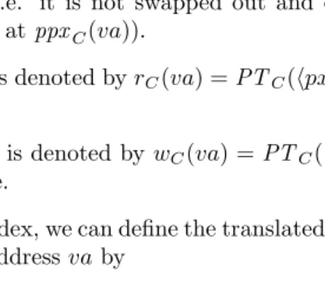
• WithppxC(va) =hPTC(hpx(va)i).ppxiwe denote the physical page index ofva. Under certain conditions (no exception is caused for the memory access), it indicates the page in main memory in which the contents ofva are stored.
• The valid bit ofvais denoted by vC(va) = PTC(hpx(va)i).v. It is 1 iff the page is valid (i.e. it is not swapped out and can be found in main memory by looking atppxC(va)).
• The read bit ofvais denoted byrC(va) =PTC(hpx(va)i).r. It is 1 iff the page is readable.
• The write bit ofvais denoted bywC(va) =PTC(hpx(va)i).w. It is 1 iff the page is writable.
With the physical page index, we can define the translated main memory address maC(va) of the virtual addressvaby
mac(va) =ppxc(va)·K+hbx(va)i
=hPTC(hpx(va)i).ppx, bx(va)i. Figure 4 shows the page-table lookup and the address translation.
If a virtual address is not valid, its page can be found in the swap memory. To look it up, we need to define a swap-memory address translation mechanism, which maps a virtual address va to a swap address sa. At the moment, the exact memory layout of the swap memory is not important, therefore, we define a trivial translation mechanisms that maps virtual addresses to an associated swap memory address by merely adding an offset sbase to them. The offset sbase should be a multiple of the page size K. We define the swap memory address saC(va) ofva bysaC(va) =sbase·K+vaand the swap space index spxC(va) byspxC(va) =sbase+hpx(va)i. Figure 5 shows this setup.
Block
hsbasei
232bytes, 220blocks of swap memory
Figure 5: Swap Memory
3.2 The Virtual Machine DLX
VA configuration of the virtual machineDLXV is a tripleCV = (RV, vm, r). The first componentRV denotes the virtual machine registers, the second component denotes the virtual memory and the third denotes the rights function. The rights function rstores access rights for each virtual addressva.1
r: [{0, . . . ,232−1} →2{r,w}]
The rights function controls accesses to virtual memory addresses. We denote accesses by a pair (va, mw) of a virtual address and a boolean flag.
• A read accesses (va,0) (which is either a fetch or a load) can be executed iffr∈r(va).
• A write access (va,1) can be executed iffw∈r(va).
Rights can only be defined for individual pages, addresses in the same page have the same access right. Formally, two virtual addressesvaandva0 that have the same page index, also must have the same access rights:
px(va) =px(va0)⇒r(va) =r(va0)
The definition of the configuration of the virtual machine implies the intended meaning of some parts of the page table:
• The read bit of page table entry for virtual addressvais set iff the read rightris element of the rights functionrof the configuration:
rC(va) = 1⇔r∈r(va)
• The same holds for the write right:
wC(va) = 1⇔w∈r(va)
• The valid bit indicates, whether we can find the contents ofvain the main memory or the swap memory. The specific address is determined by the main memory or swap memory translation function.
So, we want to satisfy the following equation:
vm(va) =
(mmC(maC(va)) ifvC(va) = 1 smC(saC(va)) otherwise
1Notation: Given a setMthe powerset, i.e. the set of all subsets, ofM is denoted by 2M.
3.3 Instruction Execution
Now we define the next step function of the specification machine and the virtual machine:
δS(C) = (R0S, mm0, sm0) δV(CV) = (R0V, vm0, r)
For the specification machine, we are interested only in the case in which the user mode is active, i.e. for this section we generally assume thatRV(mode) = 1. In case that we are in system mode the next step function is the same as for the old DLX (no translation, no restrictive rights). Additionally, we also assume, that no exception are caused for the specification machine, i.e. we will not switch to system mode. Exception handling will be considered in later lectures.
The interesting cases for the next-state functions are obviously the instruc- tion fetch and the execution of load/store operations. The definitions follow.
• For instruction fetch, we define the (invisible) instruction registers for both machines. For the virtual machine, the instruction register is obtained by reading four bytes from the location that the delayed PC points to. For the specification machine, we read four bytes from thetranslated address of the delayed PC.
IRV =vm4(DPCV)
IRS =mm4(maC(DPCS)) if¬excpC(DPCS,0) Note: the exception predicateexcpC(va, mw) has yet to be defined.
• IfIRV is no load/store instruction, the memory contents and the rights function do not change and the register update can be described by a functionf1that takes the current registers and the instruction register as input:
vm0 =vm r0 =r
R0V =f1(IRV, RV)
For the specification machine, the update is similar: ifIRSis no load/store instruction, the memory contents do not change and the register update is described by the same functionf1:
mm0=mm sm0=sm
R0S =f1(IRS, RS)
• If (any)IR is a load/store instruction, we compute the effective address by
ea=GPR(RS1(IR)) +imm(IR) Also, we have an access widthd(IR)∈ {1,2,4,8}.
For loads, the virtual machine’s load result is computed by a direct access to the virtual memory. The specification machine’s load result is com- puted by atranslatedaccess to the the main memory provided there is no translation exception.
Hence, we have:
lresultV =vmd(ea)
lresultS =mmd(maC(ea)) if ¬excp(ea,0) For both machines, the updated register content is computed by
R0 =f2(R,IR,lresult)
and the other components of the machine configuration do not change.
For stores, we have a store operandGPR(RD(IR)). The virtual machine stores the store operand in the effective address’s location of the virtual memory. The specification machine stores the store operand in thetrans- lated effective address’s location in the main memory provided there is no translation exception. Otherwise, no memory locations change.
We have:
vmd(ea) =GPR(RD(IRV))
mmd(maC(ea(IR))) =GPR(RD(IRS)) if ¬excp(ea,1)
For both machines, the updated register content is computed by a function f3 operating on the old register content and the instruction register:
R0=f3(R,IR)
3.4 Specification Machine Exceptions
27 May 2003 Repetition. We have three machines, the virtual, the specification and
the implementation machine, between which we want to establish simulation theorems:
DLXV
←−SW DLXS
←−HWDLXI
The implementation machineDLXI we have yet to define. For the other two, the important parts of our definition concerned the memory accesses.
• A configuration ofDLXV is a tripleCV = (RV, vm, r) where r: [V a→ {∅,{r},{w},{r,w}}]
is the rights function and Va = {0, . . . ,232−1} is the set of virtual addresses.
A memory access is a pair (va, mw)∈Va× {0,1}. We distinguish:
– Fetch, whereva=DPC andmw= 0
– Load, whereva=ea=GPR(RS1) +immandmw= 0 – Store, whereva=eaandmw= 1
The machine aborts ifmw= 0∧r∈/r(va) ormw= 1∧w∈/r(va).
• A configuration of DLXS is a triple CV = (RS, mm, sm). There are extra registerspto,ptl,mode, and emode∈RS\RV.
Page-table lookup and translation:
PTC(x) =mm4[hptoi+ 4x]
= 31 ppx[19 : 0] · · · r w1 0v
12 11 3 2
va=hpx(va), bx(va)iwithpx(va)∈ {0,1}20, bx(va)∈ {0,1}12 ppxC(va) =hPTC(hpx(va)i).ppxi
rC(va) =PTC(hpx(va)i).r wC(va) =PTC(hpx(va)i).w
vC(va) =PTC(hpx(va)i).v
maC(va) =ppxC(va)·K+hbx(va)ifor the page sizeK= 4096 saC(a) =sbase·K+saforsbase·K∈SaandK dividessbase The translation mechanism above (which mapsC, va tomaC(va)) we used to define the semantics of the (new)DLXS:
• In system mode,mode = 0, “nothing” new happens, no translation.
• In user mode,mode= 1, we mapva7→maC(va) and use it for the access, if¬excpC(va, mwC). The virtual addressvais either hDPCiorheai.
We have yet to define when (and which) exceptions are caused in theDLXS due to page-table lookups / address translation. We start by defining someauxiliary
signals. Let (va, mw) be a memory access. Corrected
stuff ahead!
1. The illegal operation exception illC(va, mw) is signalled if the page in- dex ofva lies outside the page-table, or the memory operation typemw
violates the rights stored in the page table entry. For mw = 0, such a violation is called read rights violation, formw= 1 it is called write rights violation. We define:
illC(va, mw) = (hpx(va)i ≥ptl)∨(mw∧ ¬wC(va))∨(¬mw∧ ¬rC(va)) 2. The pagefault exception pfC(va, mw) is signalled if the page-table entry
is not valid (and there is no illegal operation exception):
pfC(va, mw) =¬illC(va, mw)∧ ¬vC(va)
3. Both conditions are subsumed in the general translation exception condi- tionexcpC(va, mw):
excpC(va, mw) =illC(va, mw)∨pfC(va, mw)
With these definitions, we define three new types of exceptions connected to memory management:
1. An illegal memory operation exception is caused iff the fetch was an illegal operation or if the fetch has caused no translation exception but there is an illegal load/store operation:
illmC⇔illC(DPC,0)∨
¬excp(DPC,0)∧loadstore(IRS)∧illC(ea, mw(IRS)) 2. A page-fault on fetch exception is caused iff the fetch caused a page fault:
pffC⇔pf(DPC,0)
3. A page-fault on load/store exception is caused iff the fetch caused no translation exception but there was a page-faulting load/store operation:
pflsC⇔ ¬excp(DPC,0)∧loadstore(IRS)∧pfC(ea, mw(IRS)) Excursion: Interrupt Handling. In a jump-interrupt-service-routine condition (JISR= 1), the machine performs several updates simultaneously:
SR= 032 ESR=SR ECA=MCA
EPC =PC0, EDPC =DPC for repeat
EPC = nextPC0, EDPC = nextDPC for continue
EDATA=
imm26 iftrap ea ifloadstore DPC ifcontinue Conclusion of all these updates:
• the ISR can compute the interrupt levelil= min{j |ECA[j] = 1}.
• For pff, pfls and illm it can reconstruct the virtual address va that caused the interrupt: forpff, it isEDPC, forpfls it isEDATA.
pff pfls illm
JISR 17
SR[7:31]
CA[0:31]
Figure 6: JISR Computation
To protect sensitive registers in user mode, we must cause an illegal operation exception on access ofpto,ptl and several other registers if we are in user mode:
movi2s with mode, pto, ptl or emode as destination (and several others, too) should cause an ill exception.2 Hence, the definition of the illegal operation exception now depends also on themode register.
The mode register is reset onJISR and restored fromemode onrfe. This completes the specifications of our machines.
4 Hardware Implementation
Next we will:
1. Construct hardware and prove a hardware simulation theorem.
2. Write handlers for pff andpfls and prove a software simulation theorem.
Naturally, we start with 1.
Arguments for memory accesses aremode for loads, stores and fetches, and, ifmode = 1, alsoptoandptl. We want to have a lemma of the form that during one access the arguments should be stable (usingI(k, T) =iandRiS).
• For load/store, we could use extra arguments in reservation station for load/store functional unit.
• This does not work forpff, hence, we have to establish by other means, that the arguments do not change during an access.
Conjecture: only afew precautions are necessary, since
• formode = 1 the registerspto, ptl and mode will stay constant,
• For mode = 0 the registers pto, ptl and mode are not used for address computation (system mode = untranslated!).
In the following lectures, we will make this precise.
2Attention,ill6=illm!
IMMU load, DMMU store
CPU fetch
memory interface protocol
MM
Figure 7: Processor Overview with MMUs
4.1 MMU Design
30 May 2003 In our processor implementation, we have two MMUs which are placed between
the caches and the processor core. The instruction MMU is used for instruction fetches, the data MMU is used for loads and stores. This is shown in figure 7.
Recall:
RS=RV ∪ {pto,ptl,mode,emode}
C= (RS, mm, sm) C7→PTC(x) =mm4(hptoi+ 4·x)
= 31 ppx[19 : 0] · · · r w1 0v
12 11 3 2
maC(va) =hPTc(hpx(va)i).ppx, bx(va)iforva=hpx(va), bx(va)i The MMU performs translation and exception computation ifmode = 1.
The following signals form the interface between the processor and a single MMU:
• MMU inputs from the processor:
– p.addr (=DPC for instruction fetch, =eafor load/store) – pto,ptl,mode
– p.mw, p.mr processor memory write and read – m.data.infor stores
• MMU outputs to the processor:
– m.data.out(=I for instruction fetch, =doutfor load) – m.busy
– Exceptions:
∗ illm
∗ pff
∗ pfls
The interface between the MMU and the cache is unchanged, it is the old interface between the processor and the cache. Both interfaces must obey the standard memory protocol, of which figure 8 shows two examples. For a cache hit, the memory responds in the same cycle the request was started. For a cache miss, it may take many cycles, before the cache responds with¬m.busy after it has loaded the necessary line. As an input convention, the processor has to keep
addr dout
DPC mbusy
mr
Cache Hit clk
I
Cache Miss
DPC
I
Figure 8: Memory Protocol Example: Cache Hit and Cache Miss for Instruction Fetch.
1 0
1 0
< +
t
[2 : 0]
m.addr[31 : 2]
[31 : 2]
arce
(r,w,v) pte[31 : 0]
drce
m.din[31 : 0]
[11 : 0]
(p.addr[31 : 2],02) ptl[19 : 0]
[31 : 12]
[31 : 0] 02 012
pto[19 : 0]
[31 : 0] lexcp
[31 : 12]
add
p.din[31 : 0]
ar[31 : 0]
dr[31 : 0]
Figure 9: Datapaths of the MMU where p.t = t = mode and ar, dr are the address and the data register.
idle
add:
arce,add p.req &
p.t
seta:
arce p.req &
/p.t lexcp
readpte:
m.mr,drce /lexcp
m.busy
comppa:
arce
/m.busy pteexcp
read:
m.mr,drce /pteexcp &
p.mr
write:
m.mw /pteexcp &
p.mw /m.busy
m.busy
/m.busy
m.busy
p.mr p.mw
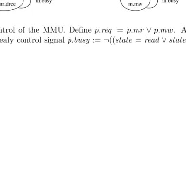
Figure 10: Control of the MMU. Define p.req :=p.mr∨p.mw. Additionally, we have the Mealy control signalp.busy :=¬((state =read∨state =write)∧
¬m.busy).
the input data and the requests signals stable (i.e. it must not change them) as long as the memory is busy.
We will examine a slow MMU design in this lecture. The datapaths of this design are shown in figure 9, the control of this design (FSD) is shown in figure 10. The busy signal of the MMU to the processor is a Mealy signal. We must pay attention that the MMU signals busy even in the first cycle of the request. Our approach is therefore, to make the MMU signal not busy only when it enters theidle state again, i.e. when it is in stateread orwriteand the cache / memory signals not busy¬m.busy:
p.busynew:=¬((state=read∨state=write)∧ ¬m.busy)
Local Correctness of the MMU. We have several cases according to the following criteria:
• Translated / Untranslated.
• Read operation / Write operation.
• Exception / No exception.
Lemma 2 (Paths) Claims about the path followed for the different cases through the FSD:
• For translated read without exception, the path followed in the FSD is idle →add →readpte+→comppa →read+→idle .
• Similar claims for all the other cases.
Lemma 3 (Correctness) In caseion path fori“happens what we want” (i.e.
what is defined by the DLXS).
Proof. We proof both lemmas only for the translated read case without exceptions. The proofs for the other cases are similar.
• Assume the request starts in cycletin stateidle: p.reqt−1= 0
p.reqt= 1 statet=idle
• In cyclet+ 1 we are in stateadd. Therefore, the address register at time t+ 2 contains the address of the page-table entry:
hart+2i=hptoit+1+ 4· hpx(p.addrt+1)i
=hptoit+ 4· hpx(p.addrt)i(if inputs stable!)
• Between timet+ 2 andt0 for somet0≥t+ 2, we access the cache to read the page-table entry. I.e., we have for ˜t∈ {t+ 2, . . . , t0−1}, thatm.busy˜t andm.mr˜t. Also, we have¬m.busyt0 andm.mrt0.
By the cache / the memory specification, the contents of the data register at timet0+1 correspond to the data read from the memory. More precisely, the memory read that is acknowledged (i.e. signalled not busy for the first time) in cyclet0 returns the data of the memory configuration in the same cyclet0 looked up at the input address that was supplied in cyclet+ 2.
drt0+1=
((?32, mmt40(art+2)) ifart+2[2] = 0 (mmt40(art+2), ?32) otherwise .
Observe, that during the whole request to the cache, the address register does not change its value, i.e. for all x ∈ {t+ 2, . . . , t0}we have arx = art+2. Since we already assume, that the processor address bus p.addr does not change, we obtain that this reads the desired page-table entry, i.e. we have
drt0+1[31 : 0] ifart+2[2] = 0 drt0+1[63 : 32] otherwise
=PTt0(hpx(p.addrt)i) .
• As we are in statecomppain timet0+1, we get that the value of the address register in timet0+1 is correct, i.e. it corresponds to the translation defined by theDLXS:
hart0+2i=maC(p.addrt)
Attention: to keep this well defined, aside from the regular inputs, the expressions
PTC(hpx(p.addr)i), pto, ptl, mode
must stay constant during the request. We will treat this problem when we integrate the MMU into the whole processor design.
• At timet0+2 we start another memory request (stateread). This requests ends at timet00for somet00≥t0+2. I.e., we have for ˜t∈ {t0+2, . . . , t00−1}, thatm.busy˜t andm.mr˜t. Also, we have¬m.busyt0 andm.mrt0. The end of this memory request t00 is also the end of the MMU request, since
¬p.busyt00.
At the time of acknowledgment, the data read from the memory configu- ration at the time of acknowledgment is returned.
So, finally we have
p.dint00 =mmt800(hart00[31 : 3],000i) .
As before, we need additional arguments for our implicit assumptions here.
4.2 MMU Integration
3 Jun 2003 In this lecture we explain how the MMU is correctly integrated into the pro-
cessor. Our local MMU correctness proof already has had several assumptions that all talk about certain inputs of the address translation being constant over the whole duration of a translation request. Guaranteeing these assumptions is a non-trivial task; in fact, we identify four groups of inputs, that all need different arguments to be provably stable. When we do this, we will (again)
IMMU DMMU CPU
pto ptl
mode to SPRs!
directly connected
MM
Figure 11: MMU SPR Inputs
mainly consider the case of a translated read access without exception. Such a request occurs for instruction fetches or data loads. Of these two cases, we will concentrate on the instruction fetch. All the other cases are similar or simpler.
We assume that the request starts at time t, i.e. p.reqt and ¬p.reqt−1 (or
¬p.busyt−1). We have seen from the proof of the last lecture, that there is a timet00> t, such that for all times ˜t∈ {t, . . . , t00−1}:p.busy˜t and¬p.busyt00.
Relevant inputs for a translated memory operation request to the MMU consist of four groupsGi:
• G0 consists of the “regular” inputs supplied by the processor, p.addr, p.mw, p.mrandp.dout.
• G1 consists of the special purpose registersptl, pto andmode.
• G2 consists of the page table.
• G3 (for reads) consists of the accessed memory contents,mm(ma(va)).
Consider now the instruction fetch of instruction Ii. The time ti at which this instruction fetch starts, is the minimal time in which the request to the instruction MMU is active and the scheduling function indicatesIi to be in the fetch stage:
ti:= min{t0|p.reqt0∧I(fetch, t0) =i}
An access that was started in cycletis not finished in cycleτ iff the busy signal is still active. We denote this by the predicatenf(t, τ) that is defined as
nf(t, τ) :=τ ≥t+ 1∧ ∀x∈ {t+ 1, . . . , τ}:p.busyx= 1 . Since our MMU is slow, fort=ti the fetch ofIi is not finished.
We define the end of the request. It is the time after the start of the requests in which the busy signal first becomes inactive:
t00(t) = min{x≥t+ 1 :p.busyx= 0}
(The existence oft00requires a liveness proof. This proof was implicit in the last lecture, it uses thatm.busy cannot stay active indefinitely for ongoing requests to the cache.)
The following lemma is an easy implication of the local MMU correctness shown in the last lecture.
Lemma 4 (Translation Lemma) Hypothesis: we assume the input signals stay constant during the access, i.e. we have for all i∈ {0, . . . ,3}
(Gi)τ= (Gti)for nf(t, τ).
Then, the data returned by the MMU is that of the translated memory location at the start of the request:
p.dint00 =mmt4(mat(p.addrt)) Proof. We have seen in the previous lecture, that
p.dint00 =mmt400(mat0(p.addrt)) . With the hypothesis, this already gives the claim.
The big question is now, how do we guarantee the hypothesis (Gi)τ= (Gi)t? As it turns, we require quite different arguments for the different i.
• G0.
By construction, p.busyτ = 1 (the new busy signal!). Hence, we have inτ+1=int forin∈ {p.addr, p.mw, p.mr, p.dout}, because the processor does not change the inputs as long as the MMU signals that it is still busy, i.e. p.busy is active. (This is an inductive argument.)
• G1.
The idea is to stall the instruction fetch. We define the fetch signal which is the read request signal for the IMMU. This definition consists of two parts.
The first part stalls the instruction fetch if there is an instruction in the decode stage (stageS1) which may modify pto, ptl or mode. The second part stalls the instruction fetch if there is a non-terminated instruction modifyingpto,ptl ormode.
IMMU.p.req=
fetch=¬(S1.full∧(S1.ID.rfe∨
S1.ID.movi2s writingpto,ptl,mode))
∧pto.v∧ptl.v∧mode.v
See figure 12 for a sketch of how the stage 1 decode signals are computed.
Assume thatIj is arfeormovi2swritingpto,ptl ormode. If it is issued at timex, then at timex+ 1 stage 1 may be empty, i.e. we possible have
I(issue, j) =x⇒ ¬S1.fullx+1 .
But at timex+ 1, one of the valid bits ofpto,ptl ormode would be zero, i.e.
∃y∈ {pto,ptl,mode}:¬y.vx+1 .
Now, assume thatIj terminates in timez, i.e. I(wB, j) =z. Then again, for all the inspected valid bits are turned on again,∀y∈ {pto,ptl,mode}: y.vz+1. Then, we can fetch.
decode
S1.ID.r f e S1.ID.movi2s
stage S1 stage S0
S1.IR S1.f ull
Figure 12: Computation of Stage 1 Decode Signals
ppx Page
Table MM
Figure 13: Page Table Convention
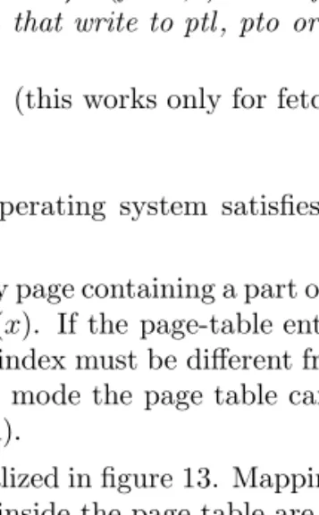
Lemma 5 (Fetch Lemma) I(fetch, t) = i∧fetcht = 1 implies all in- structionsIj withj < i that write to ptl, pto or mode have terminated.
Hence, we getGτ1=Gt1 (this works only for fetch, not for data access).
• G2, the page table.
We assume that the operating system satisfies the following page table convention:
Letsbe the index of any page containing a part of the page table. Consider a page-table entryPT(x). If the page-table entry is valid, PT(x).v = 1, then the physical page index must be different froms, i.e. hPT(x).ppxi 6=
s. Hence, in translated mode the page table cannot be accessed (neither written to or read from).
The convention is visualized in figure 13. Mappings outside the page table are allowed, mappings inside the page table are not.
The page-table convention gives us the following lemma.
Lemma 6 (Page Table Lemma) If the page-table convention holds, the page table stays constant during translation.
Proof. Consider the translated fetch ofIi starting at timet. Thus, we havemodet= 1.
There exists a cyclet0 < t, where the processor was last in system mode, i.e. modet0 = 0 and t0 is maximal (∀t˜∈ {t0+ 1, . . . , t}:mode˜t = 1).
Assume that the instruction in the write-back stage at this time t0 has indexj < i,
I(wB, t0) =j .
The instructionIjcan only be anrfeormovi2swriting themoderegister.
By the definition of the fetch signal,Ij has already terminated at time t and also by in-order termination all instructions beforeIjhave terminated.
By the page-table convention, no user mode instructionIk for j < k < i can change the page-table.
Hence, the page table does not change: Gτ2 =Gt2.
Let us reiterate. 6 Jun 2003
We have identified four groups of inputs to the MMU. The first two groups are concerned with the inputs coming from the processor:
G0:va=p.addrt, p.rdt, p.wrt, p.reqt G1:ptot,ptlt,modet
The other two groups are concerned with inputs coming from the memory:
G2:PTt
G3:mmt(mat(va)) for reads
We were in the proof of the translation lemma: if the input groupsGi do not change, the MMU computes translated read operation. We summarize the reasoning again here and treat the missing case forG3:
• G0
By generation ofp.busy
• G1
By fetch stall condition and fetch lemma.
fetch= ¬(S1.full∧(S1.ID.rfe∨S1.ID.movi2s writingpto,ptl,mode))
∧pto.v∧ptl.v∧mode.v
Fetch lemma: ifIi set the mode bit then for allj ≤i, the instruction Ij
is terminated before the translation of fetch forIi+1 starts.
• G2
By the page-table convention guaranteed by the operating system (fig- ure 13) and the page table lemma (if the page-table convention holds, the page table stays constant during translation).
• G3
Sync condition: there must be a sync (movs2i R0, IEEEf) before a fetch from a modified location. Formally, let y be a physical address. If the instruction Ii is a translated fetch from y, and instruction Ij for j < i writes to y, there must be a k with j < k < i such that Ik is a sync instruction.
For this to work, we need a strengthened sync, which prevents fetching of the next instruction already: S1.full∧S1.ID.syncshould imply ¬fetch. Lemma 7 (Sync Lemma) From the sync condition we get (G3)τ = (G3)t for allτ ∈ {t, . . . , t00}.
Proof. Omitted here, similar to the page-table lemma.
Now we can show the global fetch correctness: the instructions that the implementation machine fetches correspond to the instructions that the speci- fication machine fetches.
Theorem 1 (Fetch Theorem) LetI(fetch, t) =iand assume the translation starts in cycle t and ends in cyclet00. We claim:
p.dint00 =IRiS
Proof. Assume correct simulation until the start of cyclet. With this obtain ptot =ptoiS, ptlt=ptliS, modet =modeiS .
The special purpose register are used in the MMU without testing the valid bits!
But, by the fetch condition, the valid bits are on, since otherwise we would not yet have started to fetch.
By the assumption, the address fed into the instruction MMU is equal to the delayed PC of the specification instructioni:
IMMU.p.addrt =DPCiS
From (G2) we get thatPTt=PTiS andmat(IMMU.p.addrt) =maiS. By induction assumption, the memory contents of timetcorrespond to the memory contents of the specification machine at stepi:
mmt4(IMMU.p.addrt) =mmiS,4(maiS(DPCiS))
Abbreviate y:=maiS(DPCiS). Letj be the index of the instruction which last wrotemm(y):
j = max{k < i|kwrites mmS(y)}
From the Tomasulo proof we know thatmmt(y) =mmiS(y) if Ij is terminated at time t. This is true by the sync lemma.
By applying the translation lemma we get our claim:
IMMU.p.dint00+1=mmt4(mat(IMMU.p.addrt))
=mmiS(maiS(DPCiS))
=IRiS
Now we prove a similar theorem for a translated load. 10 Jun 2003 Assume the instructionIi is a translated load and is in the memory stage at
timet:
I(mem, t) =i
Furthermore, assume that the request signal to the data MMU is already acti- vated, i.e. DMMU.p.reqt, and thattis minimal with respect to these conditions.
Lett00 denote the end of the request. Letdi ∈ {1,2,4,8}denote the width of the operation in bytes (and mbwi ∈ {0,1}8 the corresponding byte write signals). Leteai denote the effective address.
Theorem 2 (Load Theorem) The data MMU returns at timet00+1the spec- ified load data of instructioni:
DMMU.p.dint00+1=mmiS,di(maiS(eaiS))
Proof. Assume correct simulation until the start of cycle t. Especially, this assumption already contains fetch correctness, which we proved in the fetch theorem. With this obtain
ptot =ptoiS, ptlt=ptliS, modet =modeiS .
Because of the assumption, we get that the signals fed to the data MMU correspond to their specified counterparts:
DMMU.p.addrt=eaiS
DMMU.p.mbwt=mbwiS
From this, we also obtain mat(DMMU.p.addrt) =maiS(eatS). Since we do in- order load/store, the memory contents in time t correspond to the specified memory contents in stepi, i.e. mmt =mmiS.
Thereforemmt(mat(DMMU.p.addrt)) =mmiS(maiS(eatS)).
By the assumptions onG2and in-order load/store, for allx∈ {t, . . . , t00}we also have
mmx(max(DMMU.p.addrx)) =mmiS(maiS(eatS))
This satisfies the assumptions of the translation lemma, we can conclude the claim
DMMU.p.dint00+1=mmiS,di(maiS(eaiS))
We will not prove the following theorem, which is similar to the load theorem:
Theorem 3 (Store Theorem) The data MMU executes translated stores cor- rectly.
All in all, these are the main results to obtain hardware correctness:
Theorem 4 DLXI simulates DLXS.
(Actually, we would have to go through the whole Tomasulo proof again to establish this result. We can argue, the rest of the processor hardware, apart from the MMUs, was not touched, and so, the same proof will go through without change. In a theorem prover, like in PVS, this is possiblymuch work.)
5 Software for the DLX
SWe will now talk about the software for the DLXS, especially about the page fault handler part.
The operating system software enforces a memory organization on the user program in which the memory used for OS purposes and the memory used by the hardware (→ translation) is strictly separated from the memory that the user program can access. The part used by the user program is called theuser memory, the part used by the operating system and the hardware is called system memory.
In particular, the system memory is part of the main memory. It is modelled by a set of page indices in main memorySys⊆ {0, . . . ,220−1}. The following are examples of the data structures maintained in the system memory by the operating system:
• Operating system code & data
• The page table
• sbase(from the swap memory translation: sac(va) =sbase+va)
• MRL (an index of the most recently loaded, i.e. swapped-in, page) The operating system will let the user program access a part of the main memory that is called the user memory. Through its data structure, the oper- ating system maintains two sets of page indices:
• allocP is the set of allocated pages for the user memory.
To guarantee that the user program cannot access the system memory (e.g. the page table), we want that
Sys∩allocP =∅.
• freeP⊆allocP is the set of free pages in the user memory. Anyp∈freeP is reserved for the user but has not been used yet.
After initialization, the whole user memory is free, and we havefreeP = allocP. Then, freeP will get smaller whenever a reference for a yet un- referenced page was made. When freeP = ∅, swapping starts, i.e. if there is a page fault, one page must be swapped out (written back to the swap memory) and one page must be swapped in (loaded from the swap memory).
Additionally, the operating system needs to maintain information on the used (i.e. non-free) pages of the user memory: for every such page we want to de- termine efficiently which is the virtual page index that has been mapped to it.
We present now concrete data structures with which we implement the page fault handlers.
We assume that the operating system is willing to let the user program use apages in main memory starting from the page with indexabase. These pages form the user memory. We index the user memory pages from 0 to a−1; user memory pageicorresponds to the main memory pageabase+i.
sbase a b abase
B[]
pageabase ...
pageabase+a−1 User
System
MM
PT MRL
Code Memory
Memory
Figure 14: Memory Map with the System Area and the User Area
The operating system keeps a counterb≤athat denotes the number of used (i.e. non-free) pages in the user memory. The used pages will occupy the lower part of the user memory. This means that the user memory page i is used iff i < b.
An array of words B[0 : a−1] is used to keep track of the virtual page indices of used pages in the user memory: the entryB[i] (fori∈ {0, . . . , b−1}) contains the virtual page index of the page occupying the user memory pagei.
Let validVP denote the set of all (virtual) page indices stored in the arrayB, i.e. we set
validVP ={B[0], . . . , B[b−1]}.
The setvalidVP can be used when we look for eviction pages (i.e. pages that are to be swapped out when the user memory is full—which happens when a = b). Eviction candidates can be found by choosing elements from the set validVP \ {MRL}.
The set of page indices we mentioned before can be defined in terms of the variablesa,abase andb:
allocP ={abase, . . . ,abase+a−1}
freeP ={abase+b, . . . ,abase+a−1}
Figure 14 shows a detailed memory map for our system. Recall that we use for a page index x and any memory m the notation pagem(x) to denote the contents of pagexin memory m:
pagem(x) :=m4096(x·4096)
Handler for Page-Fault on Fetch. The algorithm must handle several cases. Here, we treat only the easy case: there is a free, allocated physical page left. The other case will be treated for the handler for page-fault on load/store.
So, assumefreeP 6=∅. Letedenote the minimal element fromfreeP (in fact we must havee=b). The page fault handler has to do the following things:
1. Update the ppx-field of the faulting page-table entry point to the page indexe(where the swapped-in page will be placed):
ppx(EDP C) :=e 2. Swap in the page:
pagemm(e) :=pagesm(px(sbase+EDPC))
3. ThevalidVP has to be updated by addingpx(EDPC) to it. This can be achieved by storingpx(EDPC) in its last entry.
B[b−1] :=px(EDPC) 4. Update thefreeP set by incrementingb:
b:=b+ 1 5. Update theMRLvariable by setting
MRL:=px(EDPC).
6. Return from exception byrfe. Observe:
• Usingrfesatisfies the synchronization condition.
• Sincee∈freeP ⊆allocP andallocP∩Sys=∅we also havee /∈Sys. This helps us to keep the PT condition satisfied.
Handler for Page-Fault on Load/Store. We sketch the case forfreeP =∅.
In this case, we must swap out a page to make room in the user memory and then swap in the faulting page. Choose an eviction candidate victimefrom the set validVP\ {MRL}. (Note: eis now avirtual page index not a physical.)
This choice guaranteese6=MRL. If we do not have this, we could deadlock the user program: Consider the following, endless sequence of page faults:
1. Page-fault on fetch, swap-in the fetch page.
2. Page-fault on load-store, swap-in the load-store page by evicting the fetch page (bad!).
3. Page-fault on fetch, swap-in the fetch page by evicting the load-store page (bad!)
4. Goto 2.
So, choosing a purely random victim will not work for the proof.
Now we perform the following steps:
1. Save the eviction page:
pagesm(sbase/4096 +e) :=pagemm(ppx(e·4096))
Note: if e is the value of the array entry B[i], then of course, we have abase+i=ppx(e·4096) and can simplify the code accordingly.
2. Mark the swapped out page as invalid:
v(e·4096) = 0 3. Swap in the page:
pagemm(ppx(e·4096)) :=pagesm(px(sa(EDATA))) 4. Update theppx field and the valid bit v in the PTE:
ppx(EDATA) =ppx(e·4096) v(EDATA) = 1
5. Ifiis the index ofein the arrayB, then we must updateB[i] as follows:
B[i] :=px(EDPC) 6. Update theMRLvariable by setting
MRL:=px(EDATA).
7. Return from exception byrfe.
6 Simulation Theorem
13 Jun 2003 We have already established hardware correctness: DLXI simulates DLXV.
• DLXI is the new implementation machine, i.e. the old DLXI plus two MMUs and a few gates.
• DLXS is the new specification machine with two modes. In mode 0 (sys- tem mode), it operates like the old DLXS. In mode 1 (user mode), it uses address translation for pages that are in main memory and causes a page-fault exception otherwise.
Now we establish a simulation theorem between the virtual machineDLXV and the specification machine DLXS. DLXV is the virtual machine. It resembles the oldDLXS (assume for now: without exceptions) and has a rights function for memory protection. We assume that the rights never change.
Recall how we defined instruction execution for theDLXV and for theDLXS
(in user mode).
Instruction I0 Ik+1 Il Il+1 Im Im+1 In In+1 Io
OS User
OS User
Ik
Initialisation Phase
Figure 15: Phases of Computation ofDLXS
Have a virtual machine configuration ciV = (RVi , vmiV, riV). The (hidden) instruction register is defined by IRiV = vmiV,4(DPCiV). If IRiV is no load nor store instruction (which we denoted by ¬loadstore(IRiV)), then the next processor configurationci+1V can be computed by the functionf1applied to the instruction register and the register contents:
ci+1V = (f1(IRiV, RiV), vmiV, rVi )
Have a specification machine configuration in user modecjS = (RjS, mmjS, SmjS).
We setIRjS = (mmjS,4(maj(DPCjS))) if the instruction word is in main memory, i.e. we get no page-fault on fetch exception. TheDLXV updates its configura- tion according to the equation
cj+1S = (f1(IRjS, RjS), mmjS, smjS) .
Note: DLXS has more registers thanDLXV. These additional register do not change their value underf1. (Strictly speakingf1is another function here).
Theorem 5 DLXS and OS simulate DLXV for the user program.
In this theorem, we denote the configuration of theDLXV machine in step j bycjV. The configuration of theDLXS machine in cycleiis denoted byciS.
We define a projection Π that maps specification machine configurations to virtual machine configurations. Have cS = (cS, mmS, smS) and Π(cS) = (RV, vmV, r)∈CV. Then, the components are (uniquely) defined as follows:
• For any register namerofDLXV:
RV(r) :=Rs(r)
• r∈r(va)⇔rc(va) = 1
• w∈r(va)⇔wc(va) = 1
• vm(va) =
(mms(mac(va)) ifvc(va) = 1 sms(sac(va)) otherwise
We assume that after power-up (or reset), the machineDLXSreaches a cycle α+ 1 in which the first system mode phase is completed and the initialization of the user program is finished. This means we have modet = 0 for t≤αand modeα+1= 1.
We take the projected configuration of cycle α+ 1 to be the initialization configuration of the virtual machine.
c0V := Π(cα+1S )
The initialization procedure is actually quite easy. It guarantees that for all virtual addresses there is nothing in the main memory and the rights are noted in the page table. Let va∈Va. We must havevm(va) = sm(sa(va)), correct rights in the page table and a cleared valid bit in the page-table entry, i.e.
vα(va) = 0.
Lemma 8 (Step Lemma) Assume the i-th configuration of the specification machine and the j-th configuration of the virtual machine are equal by projec- tion, i.e. Π(ciS) =cVj. Then, the projection of the successor configuration of the next pagefault-free user mode step (of the specification machine) is equivalent to the next configuration of the virtual machine
Π(csS2(i)) =cVj+1 where the function s2 is defined in two steps:
1. We define the functions1which returns for a cycleieither the same cycle iif no pagefault occurred or the first cycle after the return of the pagefault handler:
s1(i) =
(i if ¬pffi∧ ¬pflsi min{j > i, modej} otherwise
2. Next, we define s2 for a cycle i. If there is no pagefault in cycle i, we just increment i. Otherwise, we use the s1 function to obtain the first cycle after the return of the pagefault handler. If in this cycle, there is no pagefault, we can again just increment its number. Otherwise, we at the cycle after still another execution of the pagefault handler and increment this.
In a compact, this can be written as follows:
s2(i) =
(i+ 1 if ¬pffi∧ ¬pflsi s1(s1(i)) + 1 otherwise
Note that our pagefault handlers have the property (liveness!), that in cycle s2(i)−1no pagefault occurs.
Proof. Mainly bookkeeping. Use translated accesses of theDLXS if instruc- tion / data in main memory. Otherwise, handlers swap the needed pages into the main memory.
Consider the example case thatIRjV is neither load nor store. Consider the subcase that there is no pagefault on fetch, i.e. ¬pffi.
First we verify that both instruction registers are equal:
IRiS =mmi4(mai(DPCiS))
=vmj(DPCiS) becausevc(DPCiS) = 1
=vmj(DPCjS)
=IRjV