Cache-Aware Instruction SPM Allocation for Hard Real-Time Systems
Arno Luppold
Institute of Embedded Systems Hamburg University of
Technology Germany
Arno.Luppold@tuhh.de
Christina Kittsteiner
Institute of Databases and Information Systems
Ulm University Germany
Christina.Kittsteiner@uni- ulm.de
Heiko Falk
Institute of Embedded Systems Hamburg University of
Technology Germany
Heiko.Falk@tuhh.de ABSTRACT
To improve the execution time of a program, parts of its in- structions can be allocated to a fast Scratchpad Memory (SPM) at compile time. This is a well-known technique which can be used to minimize the program’s worst-case Execution Time (WCET). However, modern embedded sys- tems often use cached main memories. An SPM allocation will inevitably lead to changes in the program’s memory layout in main memory, resulting in either improved or de- graded worst-case caching behavior.
We tackle this issue by proposing a cache-aware SPM allo- cation algorithm based on integer-linear programming which accounts for changes in the worst-case cache miss behavior.
CCS Concepts
•Mathematics of computing→Integer programming;
•Computer systems organization → Real-time sys- tem architecture; •Software and its engineering → Compilers;
Keywords
Compiler; Optimization; WCET; Real-Time; Integer-Linear Programming
1. INTRODUCTION
In hard real-time systems an application does not only have to return functionally correct results, but must also re- turn its results within a given time period. This deadline is determined by the underlying physical system, e.g., a com- bustion engine control or a car’s antilock braking system and must not be violated.
Subsequently, programs running on hard real-time sys- tems should be optimized with regard to their WCET in- stead of the average case performance. Several scientific
Permission to make digital or hard copies of all or part of this work for personal or classroom use is granted without fee provided that copies are not made or distributed for profit or commercial advantage and that copies bear this notice and the full cita- tion on the first page. Copyrights for components of this work owned by others than ACM must be honored. Abstracting with credit is permitted. To copy otherwise, or re- publish, to post on servers or to redistribute to lists, requires prior specific permission and/or a fee. Request permissions from permissions@acm.org.
SCOPES ’16, May 23-25, 2016, Sankt Goar, Germany c 2016 ACM. ISBN 978-1-4503-4320-6/16/05. . . $15.00 DOI:http://dx.doi.org/10.1145/2906363.2906369
approaches exist on automated compiler-based WCET op- timizations. One well-known technique which can lead to massive WCET improvements is a static instruction scratch- pad memory (SPM) allocation. In this optimization, timing- critical program parts are moved to the fast but small SPM im order to reduce the WCET.
An optimization using Integer-Linear Programming (ILP) exists [6] to find the set of basic blocks which is to be assigned to the SPM. Due to the ILP formulation, the approach is optimal with regard to the underlying model. However, it does not account for cached memory.
If a basic block is moved from main memory to SPM, all subsequent blocks change their position in main mem- ory, thus changing the caching behavior for better or worse.
Therefore, moving a basic block to the SPM might theoret- ically even degrade the WCET if the subsequent rearrange- ment of the blocks in main memory results in additional cache evictions.
In this paper, we extend the static instruction SPM opti- mization by [6] to account for changes in the memory layout.
We add a model to express each basic block’s address range, used cache line mapping and possible cache conflicts within the ILP.
The key contributions of this paper are:
• We modeled each basic block’s memory address range if it is located in main memory within the ILP.
• We used this address range to compute the cache lines which are occupied by each basic block.
• We integrated a cache conflict analysis into the ILP to account for cache evictions of each basic block. To our best knowledge, this is the first approach which expresses a cache model and conflict analysis as an ILP model.
• We implemented the optimization for the Infineon Tri- Core 1796 micro controller and compared the results to a cache-unaware SPM allocation.
Section 2 will first give a brief overview of related research.
Section 3 introduces the cache-unaware ILP model by [6], as well as the cache model used throughout the paper. Sec- tion 4 presents our cache-aware SPM allocation algorithm.
In Section 5, we evaluate our approach and show the im- provements on the WCET. This paper closes with a conclu- sion and an overview of future challenges.
2. RELATED WORK
Suhendra et al. [14] introduced an ILP to perform a WCET-oriented static data SPM allocation.
The approach was later adapted for instruction memo- ries [6]. The ILP based formulation has proven to be a promising optimization approach and was subsequently im- proved to optimize multiprocessing systems with regard to the system’s schedulability [13]. However, those existing approaches consider the main instruction memory as non- cached Flash memory and do therefore not account for cache hits or misses. In modern embedded systems, Flash mem- ory is often cached with cache hit times similar to the access times of the SPM.
Several works exist on WCET-oriented cache optimiza- tions. Falk and Kotthaus [7] proposed a greedy heuristic which reorganizes the position of basic blocks in the main memory to reduce the number of cache conflicts with regard to a program’s WCET. Additionally, much work has been done on cache locking techniques, e.g., [5], [9], [12], and cache partitioning [2]. All those works show that the layout of a program in cached memory may have a huge effect on the number of worst-case cache misses and subsequently on the program’s WCET. However, they do not account for the presence of an SPM.
Verma et al. [15] propose a cache-aware SPM optimiza- tion to reduce a system’s average case energy consumption using an ILP model. They operate on a relatively coarse- grained level using so-called traces. Traces are basic blocks which are located consecutively in memory and end with an unconditional jump. The presented approach relies on all traces being aligned with cache line boundaries.
The approach doesn’t offer a way to express for changes in the memory layout if a trace is moved to the SPM. Instead, NOP operations are inserted to assure alignment and pre- vent changes in the memory layout, subsequently increasing the program’s memory size. Finally, as the paper is focused on energy reduction, it cannot be directly used to minimize the WCET of a program, as the used traces are too coarse- grained to precisely model the longest execution path in the program within their ILP model.
In this paper, we present a static instruction SPM allo- cation which allows for a cache-aware SPM allocation using Integer-Linear Programming. This way, the optimization can take into account both positive and negative effects on the caching behavior if a basic block is relocated to SPM or left in Flash.
3. SYSTEM MODEL 3.1 Notational Conventions
Table 1 shows the abbreviations which are used through- out this paper. Uppercase letters describe values which are calculated outside the upcoming ILP model or are consid- ered a physical constant. They are added to ILP constraints as constants.
Lowercase letters denote values which are added to the ILP as variables and are calculated by the ILP solver. We assume that all timings are modeled as a multiple of CPU clock cycles and are therefore integer values.
Due to our focus on the existing TriCore 1796 micro con- troller, our cache model focuses on set associative caches with Least-Recently Used as replacement strategy.
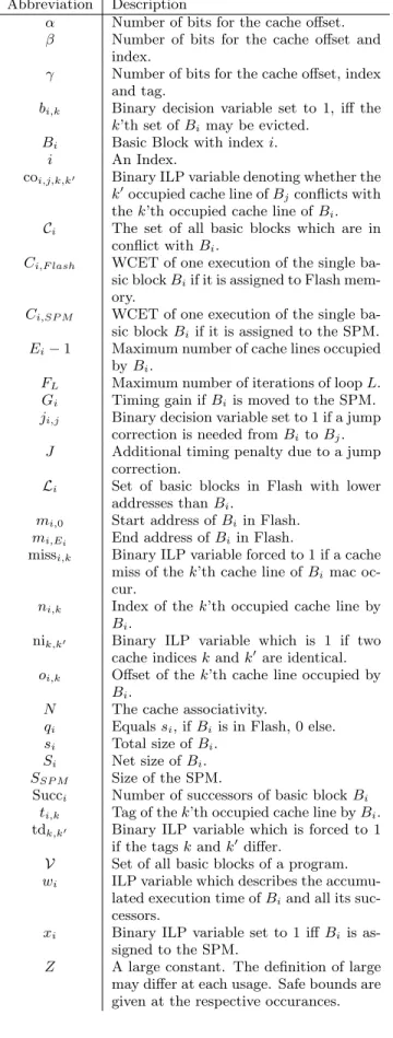
Table 1: Nomenclature used within this paper Abbreviation Description
α Number of bits for the cache offset.
β Number of bits for the cache offset and index.
γ Number of bits for the cache offset, index and tag.
bi,k Binary decision variable set to 1, iff the k’th set ofBimay be evicted.
Bi Basic Block with indexi.
i An Index.
coi,j,k,k′ Binary ILP variable denoting whether the k′occupied cache line ofBjconflicts with thek’th occupied cache line ofBi. Ci The set of all basic blocks which are in
conflict withBi.
Ci,F lash WCET of one execution of the single ba- sic blockBiif it is assigned to Flash mem- ory.
Ci,SP M WCET of one execution of the single ba- sic blockBi if it is assigned to the SPM.
Ei−1 Maximum number of cache lines occupied byBi.
FL Maximum number of iterations of loopL.
Gi Timing gain ifBiis moved to the SPM.
ji,j Binary decision variable set to 1 if a jump correction is needed fromBitoBj. J Additional timing penalty due to a jump
correction.
Li Set of basic blocks in Flash with lower addresses thanBi.
mi,0 Start address ofBiin Flash.
mi,Ei End address ofBiin Flash.
missi,k Binary ILP variable forced to 1 if a cache miss of thek’th cache line ofBi mac oc- cur.
ni,k Index of thek’th occupied cache line by Bi.
nik,k′ Binary ILP variable which is 1 if two cache indiceskandk′ are identical.
oi,k Offset of thek’th cache line occupied by Bi.
N The cache associativity.
qi Equalssi, ifBi is in Flash, 0 else.
si Total size ofBi. Si Net size ofBi. SSP M Size of the SPM.
Succi Number of successors of basic blockBi
ti,k Tag of thek’th occupied cache line byBi. tdk,k′ Binary ILP variable which is forced to 1
if the tagskandk′differ.
V Set of all basic blocks of a program.
wi ILP variable which describes the accumu- lated execution time ofBiand all its suc- cessors.
xi Binary ILP variable set to 1 iffBi is as- signed to the SPM.
Z A large constant. The definition of large may differ at each usage. Safe bounds are given at the respective occurances.
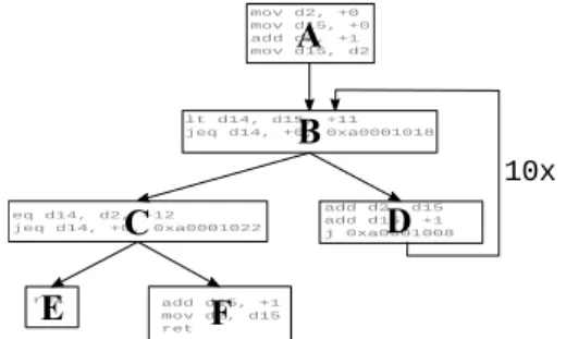
Figure 1: Control Flow of an Exemplary System
3.2 Static SPM Allocation
This section gives a brief overview of the approach origi- nally presented by [6] to describe the underlying ILP model for a static instruction SPM allocation. The model operates on a basic block level on the Control Flow Graph (CFG) of a program.
We defineCi,F lash to be the WCET of a single execution of basic blockBiif it is located in Flash memory. Ci,SP M
is the WCET ifBi is moved to the SPM. Calculating the timing gainGifor one execution ofBiis straight forward:
Gi=Ci,F lash−Ci,SP M (1)
As an example, we will model the underlying inequation system for the simple CFG depicted in Figure 1. The ILP model is built starting at the exit nodes of the CFG, implic- itly summing up the WCET of the whole program starting at each basic block. The accumulated WCETwE andwF
from the start of each exit block to the end of the program obviously equals the execution time of the exit blocks them- selves:
wE=CE,F lash−xE·GE (2) wF =CF,F lash−xF ·GF (3) For a basic blockBi, an additional binary decision variable xi is introduced. If the ILP solver choosesxito be 1, then the basic block will be assigned to SPM, otherwise the block remains in Flash memory.
If a basic block has one successor, it is modeled by its own execution time and the accumulated WCET of its successor as additional summand. If a block has multiple successors, an inequation is added for each successor. For basic block BC in the exemplary presented CFG, this leads to:
wC≥CC,F lash−xC·GC+jC,E·J+wE (4) wC≥CC,F lash−xC·GC+ +jC,F·J+wF (5) The additional binary decision variablejC,Ewill be set to 1 iffCis assigned to SPM and its successorEin the CFG stays in the Flash memory or vice versa. In this case, additional code must be added in order to create valid jump instruc- tions to handle the displacement between the two memory regions. J is a constant to account for the timing costs of this additional code. jC,F is defined accordingly.
To prevent cyclic dependencies in the ILP formulation which would result in an infeasible inequation system, loops are linearized by converting them into a sequential meta ba- sic block, whose execution timewEntryis then multiplied by the maximum number of loop iterations. Function calls can be modeled accordingly.
Following this scheme, inequations can be defined for the whole CFG:
wA≥CA,F lash−xA·GA+wLoop+jA,B·J (6) wLoop≥cLoop+CB,F lash−xB·GB+jB,C·J+wC (7)
cLoop≥10·wEntry (8)
wEntry≥CB,F lash−xB·GB+jB,D·J+wD (9) wD≥CD,F lash−xD·GD+jD,B·J (10) Because memory fetches are much faster from SPM than from Flash memory, J differs depending on whether the jump correction code is placed in SPM or not. We accounted for this, but because it is not necessary for understanding the proposed cache-aware allocation, we will not further discuss this.
It can be further observed, that the execution time of blockBBis accounted twice: Once in equation (7) and once in equation (9). This stems from the fact that if the loop is executed 10 times, the entry node BB is actually executed 11 times: 10 times the conditional jump enters the loop, and one time the conditional jump precedes to executing block BC.
The jump penalty decision variablejA,B can be modeled as logical XOR betweenxAandxB:
h1≥xA−xB (11)
h1≤xA (12)
h1≤1−xB (13)
h2≥ −xA+xB (14)
h2≤1−xA (15)
h2≤xB (16)
jA,B≤h1+h2 (17)
jA,B≥h1 (18)
jA,B≥h2 (19)
h1 andh2are binary auxiliary variables which are not used elsewhere in the ILP formulation. Newly added auxiliary variables are needed for each XOR formulation. These in- equations ensure thatjA,Bis forced to 1 if and only if exactly one ofxA orxB equals 1.
Finally, one additional constraint must restrict the num- ber of basic blocks which are assigned to the SPM due to the SPM’s limited sizeSSP M. If the original size of a basic blockBiis defined asSi, andBi’s successor isBj, the total size ofBican be expressed by:
si=Si+ji,j·SJump (20) The sum of all sizes over all basic blocks can now be lim- ited to the size of the SPMSSP M:
SSP M ≥ X
∀Bi∈V
xi·si (21) withVbeing the set of all basic blocks of the program.
IfBihas multiple successors, both successors’ jump terms must be added. For the exemplary CFG, this results in:
sA=SA+jA,B·SJump (22) sB=SB+jB,C·SJump+jB,D·SJump
· · ·
SSP M≥xA·sA+xB·sB+xC·sC+ xD·sD+xE·sE+xF·sF
The products like xi·si in equation (21) are not linear, as two variables are multiplied. However, because xi is a binary decision variable, the product can be linearized by expressing it as a conditional. This has been previously described by, e.g., [3].
To achieve best results, platform-specific characteristics like branch prediction awareness have previously been pre- sented [13]. We included the proposed branch prediction model, but, due to the lack of novelty and direct relevance for the proposed cache-aware SPM allocation, we will not further describe it in this work.
In this paper, we focus on single-tasking systems. The ILP objective function can therefore be chosen to minimize the accumulated WCET of the program’s entrypointwA:
MinimizewA (23)
The ILP solver will now assign those basic blocks to the SPM which lead to the maximum overall reduction of the WCET.
4. ACCOUNTING FOR CACHES 4.1 Describing the Memory
To be able to account for caching effects within the ILP, the address range of each basic block which is not moved to the SPM must be modeled. This can then be used to determine which cache lines are used by each block. In this paper, we assume that the program’s first basic block is located at memory address 0 relative to the start of the Flash memory region. However, it is trivial to add a constant offset to the inequation system if needed.
As we focus our optimization on the Infineon TriCore mi- cro controller, we assume an N-way set associative cache with a Least Recently Used (LRU) replacement strategy.
We first model the start address mi,0 and end address mi,Ei of each block Bi. These addresses are then used to calculate the cache lines a basic block occupies. Finally, this information is used in combination with the program’s control flow graph to add inequations which model possible cache evictions.
If a basic blockBi is assigned to the SPM (i.e.,xi = 1), the block’s memory addresses are not relevant for this opti- mization, as the block will obviously neither cause nor suffer from a cache eviction. Therefore, we do not add any inequa- tions specifying the address behavior in this case. Ifxi= 1, then the memory address will not be used for modeling the block’s actual execution time, therefore the ILP solver may setmi,0 andmi,Ei to an arbitrary value.
We define the rank of a basic block by its position in mem- ory relative to other basic blocks, if all blocks are assigned to Flash memory. A basic blockBj has a lower rank than Bi if its address in memory is lower. With mi,0 being the start address of a basic blockBi,Liis the set of basic blocks which have a lower address in memory if they are not moved to the SPM:
Li={Bj|mj,0< mi,0} (24) When a basic block is moved from Flash to SPM, the order of all basic blocks which reside in the Flash memory is not changed. As a result, for each given basic blockBi
which resides in Flash,Bi’s start address is determined by all those blocks which also stay in Flash memory and have
a lower rank. With this information, the start addressmi,0
of each block Bi as well as its end address mi,Ei can be modeled using integer-linear programming:
mi,0 = X
j∈Li
sj·(1−xj) (25) mi,Ei = mi,0+si (26) xj is the the binary decision variable, which was intro- duced in equation (2) to denote whether blockBjis moved to the SPM or not. sj is the overall size of blockBj from equation (20).
Equation (25) is not linear, as a binary decision variable is multiplied with an integer variable. However, the equation may be transformed to a set of linear inequations. For this, we introduce the auxiliary integer variable qj ∈ Z+0. We define:
mi,0 = X
j∈Li
qj (27)
with
qj=
(sj ifxj= 0
0 else. (28)
This conditional expression may be re-written as:
qj ≥sj−xj·Z (29) qj ≤sj+xj·Z (30) qj ≤Z−xj·Z (31) Zis a large number which must be bigger than the maximum size of the basic block. Inequations (29) and (30) ensure that qj =sj ifxj = 0. The two inequations will always hold for xj = 1, thereforeqj may take arbitrary values. Therefore, inequation (31) is used to enforceqj = 0 in case ofxj= 1.
Becauseqj∈Z+0,qj must not be set to a negative value by the ILP solver.
Being able to express both start and end address of each basic block which resides in Flash memory in the ILP, we can now model which cache lines are occupied by each block in the next section.
4.2 Modeling the First and Last Cache Sets
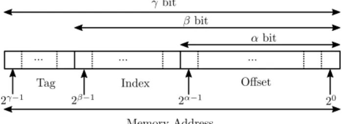
Figure 2: Mapping of a memory address to its cache parameters [11, App. B].
Figure 2 shows how a given memory address is associated with a corresponding cache line. The bits αthroughβ−1 determine the range of the cache line index which determines the cache line a memory block will be mapped to. For any given architecture,α,βandγare known constants. In nor- mal programming, one can use Boolean operations and shift
instructions to calculate the index of a given memory ad- dress. However, in an integer linear equation system, shift and modulo operators cannot be used. To solve this prob- lem, we can decompose an addressmi,ν, which maps to the ν’th cache line of basic blockBi, using its base number rep- resentation:
mi,ν = 20·oi,ν+ 2α·ni,ν+ 2β·ti,ν (32)
0 ≤ oi,ν≤2α−1 (33)
0 ≤ ni,ν≤2β−α−1 (34)
0 ≤ ti,ν ≤2γ−β−1 (35)
oi,ν is an ILP variable which will hold the offset of block Bi at its addressmi,ν. Accordingly,ni,ν signifies the index andti,ν the cache tag.
While this formulation may look unfamiliar at first, it is basically a base factor decomposition. As an example, assumeγ = 6 andmi = 35. Then, the dyadic base factor decomposition of 35 may be written:
35 = 1·25+ 0·24+ 0·23+ 0·22+ 1·21+ 1·20 (36) It is obvious that there exists only one distinct base factor decomposition.
Instead of using a full base factor decomposition, we can also combine summands without loosing the unambiguous- ness of the representation. As an arbitrary example, we can setα= 1 andβ= 3:
35 = 20·oi+ 21·n+ 23·t (37)
0≤o≤21−1 = 1 (38)
0≤n≤23−1−1 = 3 (39) 0≤t≤26−3−1 = 7 (40) As we limit each factor such that its term may not overlap with a term with a higher order, there is still only one valid decomposition, which is:
35 = 20·1 + 21·1 + 24·2 (41) As a result, equations (32) to (35) yield an unambiguous result. By applying the equations to both start and end addresses, we can create inequations to calculate the first and the last cache line which is occupied by a given block Bi:
mi,0 = 20·oi,0+ 2α·ni,0+ 2β·ti,0 (42) mi,Ei = 20·oi,Ei+ 2α·ni,Ei+ 2β·ti,Ei (43) With the maximum sizeSi,max, the basic blockBi will oc- cupy at mostlS
i,max 2α
m+ 1 cache lines. The additional cache line stems from the fact that the start of a basic block might not be aligned with the start of a cache line. Therefore, even a tiny basic block might reside in two different cache lines.
We defineEi+ 1 as the maximum number of cache sets which may be occupied byBi. Therefore:
Ei= Si,max
2α−1
(44) mi,0denotes the block’s start address,mi,Ei the block’s end address. As a result,ni,0 describes Bi’s first and ni,Ei its last cache line. ni,k, k = 1, . . . , Ei−1 denotes the index of thk’th occupied cache line ofBi. Block offsets and tags are defined accordingly.
4.3 Calculating Corresponding Cache Lines
To model the number of cache misses along the longest possible path within the program’s control-flow, the so-called Worst-Case Execution Path (WCEP), we need to express which basic block occupies which cache lines. Using the re- sults of the previous section, we can express the first and the last set which is occupied in the cache as ILP variables.
However, depending on its size, a basic block may ob- viously occupy more than two cache lines. Additionally, the number of occupied cache lines may change if additional code for jump corrections has to be inserted. Finally, a basic block might get bigger than the cache, resulting in multiple occupations of the same cache line. Depending on the cache associativity, a block might even evict itself from the cache.
We assume that a basic block will always be smaller than the net cache size. If a basic block is too large, it may be split into smaller parts for the optimization to comply with this requirement. The net cache size is determined by the overall cache size divided by the cache’s associativity. For caches with parameters which are determined as shown in Figure 2, the net size is determined by the sum of bits which are used for the index and the offset. As a result, the size of a basic block is therefore limited to 2β−1 byte.
As basic blocks are usually not aligned with the cache boundaries, all memory addresses which belong to a given basic block will map to at most two different tags and 2β−α cache lines.
The maximum size of a basic block is known before for- mulating the ILP by summing its net size and the maximum size of additional jump instructions:
Si,max=Si+SJump·Succi (45) Succiis the number of successors of basic blockBi.
The tag and indexti,0 andni,0 for the first andti,Ei and ni,Ei for the last occupied cache line have been modeled in the previous section. For s = 0 and Ei = lS
i,max 2α−1
m, each middle set’s parametersni,k andti,kwithk= 1,· · ·, Ei−1 can be calculated by incrementing ni,k−1 by 1 using the formulation from equation (32). As the offset is not needed, it can be left out and we can express the increment by:
2β−α·ti,k−1+ni,k−1+ 1 = 2β−α·ti,k+ni,k (46) To ensure valid cache index and tag sizes, the bounds from equations (34) and (35) are applied to the variables.
These variables can now be used to express whether and for which parts of a basic block a cache eviction may occur.
4.4 Determine Possible Conflicts
In a program’s control flow, a cache conflict between two blocks can only occur, if the first block is executed more than once and the second block might be fetched from Flash mem- ory between two consecutive executions of the first block. If the first condition is not fulfilled, evicting the first block from cache will not lead to any timing penalties, as the block is never needed again. If the second block is not fetched be- tween two consecutive executions of the first block, it can ob- viously not evict it from memory. Therefore, cache conflicts are typically created either by instructions within a (pos- sibly nested) loop or by code of a function which is called within a loop, therefore possibly evicting code from the loop.
Additionally, the instructions of a function may be evicted by instructions which are executed between two subsequent
function calls.
We define a basic blockBi to be in conflict with another blockBj, if Bj may be executed between two subsequent executions ofBi. In this case, mapping both blocks to the same cache line could lead to a cache miss forBi. We define Cias the set of all blocks which are in conflict withBi. Due to the significant computational complexity, we currently only consider blocks in loops and nested loops within each function separately in the ILP’s conflict analysis.
Context and infeasible path analysis on the control flow graph as well as global conflict analysis across different func- tions may provide even better solutions. However, they also come at the cost of further increasing the ILP’s complexity and solving time. We did therefore not consider them within this paper.
For two basic blocksBi andBj, a cache conflict occurs if and only if the blocks are in conflict and at least one of each blocks’ cache indexni,k andnj,k′ are equal and the blocks’
cache tagsti,k, k = 0, . . . , Ei and tj,k′, k′ = 0, . . . , Ej are not equal. Therefore, all occupied cache lines of both basic blocks have to be compared pairwise.
If both blocks have different cache indices, they will not map to the same cache line. If they share the same cache in- dex but also the same cache tag, they use the identical cache line and therefore do not evict each other. If a cache conflict exists betweenBiandBj,Bimay be evicted from cache by Bj, depending on the cache’s associativity and replacement policy.
For two blocks which are in conflict with each other, we can describe a cache conflictcoi,j,k,k′ between a cache line kofBiand a cache linek′ofBj:
coi,j,k,k′ =
(1 if (nj,k′ =ni,k)∧(tj,k′ 6=ti,k)
0 else. (47)
coi,j,k,k′ can be expressed as a set of ILP inequations in two stages. First, we introduce a binary decision variable tdk,k′ which is forced to 1 if the tags differ:
ti,k+ tdk,k′·Z≥tj,k′ (48) tj,k′+ tdk,k′·Z≥ti,k (49) Again,Z is a sufficiently large number. In this case, a safe value forZ is the maximal allowed tag number.
We can now model another binary decision variable nik,k′
which is forced to 1 if both indices are identical:
ni,k−nj,k′+ nik,k′·Z≥0 (50) nj,k′−ni,k−nik,k′·Z≤0 (51) ni,k−nj,k′+y·Z≥nik,k′ (52) nj,k′−ni,k+ (1−y)·Z≥nik,k′ (53) yis a binary auxiliary variable which is not used elsewhere.
Equations (50) and (51) force nik,k′ to 1 if the cache indices are not identical. In case of identical indices, nik,k′ can be set arbitrarily by the ILP solver. Therefore, equations force nik,k′ to 0 if both indices are identical. Again, Z is a sufficiently large number. Here, a safe lower bound is given by the maximum number of cache lines.
We can now finally model coi,j,k,k′:
y′= 1−nik,k′ (54) coi,j,k,k′≥tdk,k′+y′−1 (55)
coi,j,k,k′≤y′ (56)
coi,j,k,k′≤tdk,k′ (57)
y′ is yet another binary auxiliary variable which is needed to invert nik,k′. It is not used elsewhere. For each nik,k′ a separate binary auxiliary variabley′ has to be created.
Because our approach targets caches with Least Recently Used (LRU) replacement policy, a block may be evicted from cache in a worst-case scenario, if the number of conflicting blocks reaches the cache’s associativityN. For example, in a 2-way associative cache, a single basic blockBj can never evict parts ofBifrom cache. However, if two blocksBjand Bk are both in conflict withBi, and all blocks map to the same cache lines,Bimay be evicted between two consecutive executiosn.
Therefore, all cache conflicts are summed up for each cache setk of each basic blockBi and are compared to the cache’s associativityN. We introduce a binary variablebk,i
which will then be forced to 1 if the number of conflicting blocks is equal to or bigger than the cache associativityN:
−bk,i· Z+X
j∈C Ej
X
k′=0
coi,j,k,k′≤N−1 (58) whereEj−1 is the maximum number of cache lines which may be occupied byBj.
A miss will occur ifbi,kis 1 andBiis not in the SPM, i.e., xi= 0. Therefore, a binary decision variable missi,k which accounts for a possible cache miss of the k’th cache line of Bican be expressed as:
missi,k≥bi,k−xi (59)
missi,k≤bi,k (60)
missi,k≤1−xi (61)
which leads to the final inequation to model the accumu- lated WCET of a basic block, based on equation (5):
wi≥ Ci,F lash,Hit−xC·GC+X
k
mi,k·PM iss+ (62) jC,F ·J+wF
where Ci,F lash,Hit is the static WCET of Bi in case of a cache hit, and PM iss is the constant timing penalty of a single cache miss.
It should be mentioned that the presented approach does not model the LRU caching behavior precisely. We assumed fixed costs which have to be added in case of a necessary jump correction. However, jump correction costs may vary, depending on the actual steps which have to be performed.
For jump displacements of up to 32 bit, the jump target is read from one of the CPU’s registers. If no register is avail- able, additional spill code has to be added which leads to jitter in both the jump timing penaltyJ and the size costs SJump of the added instructions. Additionally, the linker can introduce NOP instructions in order to align functions to improve the utilization of the TriCore’s fetch unit. We did not model such effects to not even further increase the ILP’s complexity. As a result, the mapping of basic blocks to cache lines may not be exact, as will be further illustrated in the
adpcm_decoder adpcm_encoder binarysearch bsort100 compressdata countnegative
cover crc duff edn
expint fac fdct fft1 fibcall fir insertsort janne_complex
jfdctint lcdnum lms
ludcmp matmult minver ndes ns petrinet prime qsort-exam qurt recursion select sqrt
statemate st
0.5 0.6 0.7 0.8 0.9 1.0 1.1
Relative WCET Change
20% 40% 60% 80% 100%
Figure 3: Relative Improvement of the WCET due to the cache-awareness of the SPM allocation for different relative SPM and cache sizes.
20 40 60 80 100
Relative Cache and SPM size (percent) 100
101 102 103 104 105
ILP Solving Time [seconds]
Figure 4: ILP solving time for the cache-aware SPM allocation.
upcoming evaluation section. Therefore, the ILP model may under or over approximate the cache miss behavior. Addi- tionally, due to the massive complexity, the conflict analysis is quite basic compared to the current state of the art when it comes to WCET analysis. However, the model provides a good approximation of the caching behavior which basically points the ILP solver into the right direction to determine which basic blocks should be assigned to the SPM. For safe and tight WCET estimates a dedicated WCET analyzing tool like AbsInt aiT [1] should be used to analyze the opti- mized program.
5. EVALUATION
We implemented the approach described above for the In- fineon TriCore 1796 micro controller which features a 2-way set associative cache with LRU replacement strategy. We used the WCET-aware compiler framework WCC [8] as basis for our optimization. Memory accesses in case of a cache hit as well as in case of a fetch from the SPM can happen within one CPU cycle without a timing penalty for the memory ac- cess. Fetches of blocks which are not in the cache will result in a penalty of 6 cycles. The SPM is programmed at sys- tem startup prior to executing the program’smain routine.
Therefore, it is not necessary to add the timing overhead of programming the SPM itself to the program’s WCET.
We based the implementation on our own compiler frame- work. We evaluated our proposed approach using the MRTC benchmark suite [10]. The benchmarks are available with annotated loop bounds from [4]. The benchmarkduffcan- not be optimized, as it contains irregular loops which cannot be handled by the underlying ILP model.
All timing constants for each basic block as well as the WCET of the optimized benchmarks were calculated using AbsInt aiT version b217166 [1]. aiT features a configuration switch to assume each memory access as a cache hit. This was used to calculate the underlying WCET of each basic block in case of a cache hit which is needed in equation (62).
The optimizations were performed on an Intel Xeon server using IBM CPLEX 12.5.
As discussed at the end of Section 4.4, the ILP model may slightly over- or under-approximate the number of cache misses. Additionally, the underlying ILP model is neither meant nor able to precisely analyze the micro-architectural behavior of the target CPU. Therefore, the WCET as re- turned by the ILP solver should not be used to evaluate the optimization’s quality. We therefore analyzed all op- timized and linked programs, both with cache-aware and cache-unaware SPM allocation, using the AbsInt aiT tim- ing analyzer. All presented results are based on the precise WCET estimates which were returned by aiT. When using aiT for these final evaluations, aiT will always perform its regular cache analysis, thus returning as tight WCET esti- mates as possible.
To illustrate the effect of the cache and SPM size on the optimization, we optimized each benchmark for several SPM and cache sizes. As a starting point, we defined that the size of each SPM and instruction cache equals 20% of the program’s code size in each case. We then subsequently increased both values simultaneously to 40, . . . ,100% of its code size.
For each SPM and cache size, we performed both the cache-aware and the cache-unaware optimization. Prior to the optimization, we applied a couple of standard compiler optimizations like value propagation, removal of redundant code or the removal of unneeded function arguments. Our
applied standard optimizations focus on the benchmarks’
average-case runtime behavior and are comparable to gcc’s
−O2 optimization level.
Figure 3 shows the results as quotient between the WCET after cache-aware SPM allocation and the cache-unaware SPM allocation. I.e., a value of 1.0 means that the cache- aware SPM allocation leads to the same WCET as the cache- unaware SPM allocation. Results smaller than 1 show that the cache-aware optimization could reduce the WCET more than the cache-unaware allocation. Results larger than 1 indicate an increase of the WCET, therefore applying the cache-aware optimization actually leads to worse results than running the cache-unaware version.
It can be observed that a few benchmarks like adpcm_- encoder, binarysearchand countnegativeyield a higher WCET. As discussed at the end of Section 4.4, the actual block addresses may be predicted slightly imprecise by the ILP model. For benchmarks with only small optimization potential, this can lead to the observed increase in the worst- case execution time.
As described above, each of the 34 evaluated benchmarks was evaluated for 5 different cache and SPM sizes. From the resulting 170 optimization runs, 41 were left out as IBM CPLEX could not solve the underlying ILP model within several hours. Especially forpetrinet, no solution could be found for any cache and SPM size within reasonable time.
Forminver, only for a cache and SPM size of 80% a result could be calculated.
To reduce the optimization time of the cache optimization, tuning CPLEX’s timing parameters significantly helped for some benchmarks. For example, solving time of the ILP for the ns benchmark at an SPM and cache size of 80% was reduced from over 2 hours to 50 seconds on our evaluation server by reducing CPLEX’s optimality precision to 5%. At the same time, the WCET of the optimized program as re- ported by aiT did not change at all. However, this setting ac- tually lead to increased solving times for other benchmarks, thus they could not be used as a general tuning method.
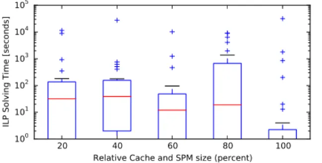
Figure 4 shows an overview of the time needed by the ILP solver to solve the cache-aware ILP allocation prob- lem as boxplot. The red line denotes the median solving time. The boxes contain all solving times between the first and the third quartiles. The whiskers are limited by the 25th and 75th percentile. As discussed above, solving times are heavily dependent on the solver’s settings and ideal set- tings may vary from benchmark to benchmark. As we did not try to find ideal settings for each and every benchmark, these numbers should be seen as a rough estimate only. For the cache-unaware optimization, the ILP was usually solved within well under 1 second. The maximum time needed was 18 seconds for thepetrinetbenchmark with an SPM and cache size of 80%.
Despite the optimization runtime, several results show the huge impact of a cache-aware SPM optimization. For an SPM and cache size of 40% of the program size, the WCET of thejanne_complexbenchmark could be reduced from 657 cycles after applying the cache-unaware SPM allocation to only 358 cycles when using the cache-aware allocation.
Other benchmarks show improvements in the WCET be- tween 10% and 20% as shown in Figure 3. Considering caching effects in the instruction SPM allocation can there- fore lead to massive further improvements on the program’s worst-case runtime behavior.
6. CONCLUSIONS
We showed that considering caching effects when perform- ing instruction SPM allocation of basic blocks may massively improve the program’s WCET. We proposed an extended ILP which models the addresses and occupied cache lines of each basic block, thus enabling us to integrate a cache conflict analysis into the ILP. As peak value, our proposed cache-aware SPM allocation could reduce the WCET of a benchmark by almost 50% compared to the cache-unaware SPM allocation.
On the downside, the proposed approach has a huge com- putational complexity, which significantly affects its usabil- ity for large benchmarks and real-world problems. Future work will therefore focus on improving the optimization’s runtime while still maintaining good or nearly-optimal re- sults. Additionally, we aim at heuristic approaches like ge- netic algorithms or simulated annealing and compare their results regarding both optimization quality and time to the results of the ILP approach.
7. ACKNOWLEDGMENTS
This work received funding from Deutsche Forschungsge- meinschaft (DFG) under grant FA 1017/1-2. This work was partially supported by COST Action IC1202: Timing Anal- ysis On Code-Level (TACLe).
8. REFERENCES
[1] AbsInt Angewandte Informatik, GmbH. aiT Worst-Case Execution Time Analyzers, 2016.
[2] S. Altmeyer, R. Douma, W. Lunniss, and R. I. Davis.
Evaluation of Cache Partitioning for Hard Real-Time Systems. InProceedings of the 26th Euromicro Conference on Real-Time Systems, pages 15–26, 2014.
[3] J. Bisschop.AIMMS. Optimization Modeling. Paragon Decision Technology, Haarlem, Netherlands, 3rd edition, 2009.
[4] COST. European Cooperation in Science and Technology. TACLe. Timing Analysis on Code-Level.
http://www.tacle.eu/index.php/activities/taclebench, 2016.
[5] H. Ding, Y. Liang, and T. Mitra. WCET-Centric Dynamic Instruction Cache Locking. InProceedings of Design, Automation & Test in Europe Conference &
Exhibition, pages 1–6, Dresden, Germany, 2014.
[6] H. Falk and J. C. Kleinsorge. Optimal Static WCET-aware Scratchpad Allocation of Program Code. InProceedings of the 46th Design Automation Conference, pages 732–737, San Francisco, USA, 2009.
[7] H. Falk and H. Kotthaus. WCET-driven Cache-aware Code Positioning. InProceedings of the International Conference on Compilers, Architectures and Synthesis for Embedded Systems, pages 145–154, Taipei, Taiwan, 2011.
[8] H. Falk and P. Lokuciejewski. A Compiler Framework for the Reduction of Worst-Case Execution Times.
Real-Time Systems, 46(2):251–298, 2010.
[9] H. Falk, S. Plazar, and H. Theiling. Compile-Time Decided Instruction Cache Locking Using Worst-Case Execution Paths. InProceedings of the 5th
IEEE/ACM/IFIP International Conference on
Hardware/Software Codesign and System Synthesis, pages 143 –148, Salzburg, Austria, 2007.
[10] J. Gustafsson, A. Betts, A. Ermedahl, and B. Lisper.
The M¨alardalen WCET benchmarks – past, present and future. In B. Lisper, editor,Proceedings of the 10th International Workshop on Worst-Case Execution Time, pages 137–147, Brussels, Belgium, 2010.
[11] J. L. Hennessy and D. A. Patterson.Computer Architecture. A Quantitative Approach. Morgan Kaufmann, Waltham, MA, fith edition, 2012.
[12] T. Liu, M. Li, and C. Xue. Minimizing WCET for Real-Time Embedded Systems via Static Instruction Cache Locking. InProceedings of the 15th IEEE Real-Time and Embedded Technology and Applications Symposium, pages 35–44, San Francisco, USA, 2009.
[13] A. Luppold and H. Falk. Code Optimization of Periodic Preemptive Hard Real-Time Multitasking Systems. InProceedings of 18th International Symposium on Real-Time Distributed Computing, pages 35–42, Auckland, New-Zealand, 2015.
[14] V. Suhendra, T. Mitra, A. Roychoudhury, et al.
WCET Centric Data Allocation to Scratchpad Memory. InProceedings of Real-Time Systems Symposium, pages 223–232, San Antonio, Texas, USA, 2005.
[15] M. Verma, L. Wehmeyer, and P. Marwedel.
Cache-Aware Scratchpad Allocation Algorithm. In Proceedings of the Conference on Design, Automation and Test in Europe, pages 1264 – 1269, Washington, DC, USA, 2004.