MANFRED REICHERT reichert@informatik.uni-ulm.de
PETER DADAM dadam@informatik.uni-ulm.de
University of Ulm, Dept. Databases and Information Systems, D-89069 Ulm, Germany
Abstract. Today’s workflow management systems (WFMSs) are only applicable in a secure and safe manner if the business process (BP) to be supported is well-structured and there is no need for ad hoc deviations at run-time. As only few BPs are static in this sense, this significantly limits the applicability of current workflow (WF) technology. On the other hand, to support dynamic deviations from premodeled task sequences must not mean that the responsibility for the avoidance of consistency problems and run-time errors is now completely shifted to the (naive) end user. In this paper we present a formal foundation for the support of dynamic structural changes of running WF instances. Based upon a formal WF model (ADEPT), we define a complete and minimal set of change operations (ADEPTflex) that support users in modifying the structure of a running WF, while maintaining its (structural) correctness and consistency. The correctness properties defined by ADEPT are used to determine whether a specific change can be applied to a given WF instance or not. If these properties are violated, the change is either rejected or the correctness must be restored by handling the exceptions resulting from the change. We discuss basic issues with respect to the management of changes and the undoing of temporary changes at the instance level. Recently we have started the design and implementation of ADEPTworkflow, the ADEPT workflow engine, which will make use of the change facilities presented in this paper.
Keywords: workflow management, exception handling, dynamic change, adaptive workflows
1. Introduction
Process-oriented workflow management systems (WFMSs) (Georgakopoulos et al., 1995;
Hsu, 1995; Leymann and Altenhuber, 1994) offer a promising approach for the development of business applications that directly follow the execution logic of the underlying business process (BP). The separation of the applications control structures from the implementation of its task programs contributes to simplify and to speed up application development, and enables the run-time system to assist users in coordinating and scheduling the tasks of a BP.
Current process-oriented WFMSs are applicable in a reliable and secure manner only if the BP to be supported is well-structured and there is no need for ad hoc deviations or dynamic extensions at run-time (see, Barthelmess and Wainer, 1995; Ellis et al., 1995;
Siebert, 1996; Reichert and Dadam, 1997a). As only few BPs are static in this sense, this significantly limits the benefit and the applicability of current workflow (WF) technol- ogy. As an example, consider BPs from the clinical domain (see, Reichert et al., 1996, 1997b), where it is often not convenient and cost-effective to capture all possible task sequences in advance. There are several reasons for this: firstly, there are many WFs whose planning and execution overlap (dynamically evolving WF ) or which are completely
specified at run-time (ad hoc WF); secondly, unplanned events and exceptions frequently occur leading to ad hoc deviations from the preplanned WFs. Exceptions cover cases such as requests to deviate from standard processes due to an external event (e.g., in case of an acute emergency), failed tasks (e.g., when prerequisites for a medical intervention are violated), incomplete or erroneous information in task inputs and outputs (e.g., incomplete medical orders), or situations that arise from mismatches between the real processes within the organization and their computerized counterparts (e.g., due to incomplete or faulty WF specifications or due to organizational changes) (Strong and Miller, 1995; Meyer, 1996). Since WF designers are generally not capable to predict all possible exceptions and events beforehand and to capture them in the design of a WF, the WFMS does not always have sufficient knowledge to handle these situations alone. Instead, user involve- ment is required in order to resolve exceptions and to deal with unplanned events. Hence, the resulting requirements are far more challenging than those faced by standard transac- tion technology and advanced transaction models (Worah and Sheth, 1997; Elmargarmid, 1992).
A basic step towards more flexibility is the effective and efficient support of ad hoc modifications and well-aimed extensions of processes during their execution. So a WFMS must provide functions for adding or deleting tasks as well as whole task blocks and for changing predefined task sequences, e.g., by allowing users to skip tasks, with or without finishing them later, to work on tasks although the conditions for their execution are not yet completely satisfied, or to serialize two tasks that were previously allowed to run in parallel. Ad hoc changes may also concern single attributes of a WF object (e.g., a task).
Examples are the reassignment of a task or the modification of a task’s deadline. As these changes are less critical to handle than structural changes, we do not consider them further in this paper.
1.1. Problem description
To allow users to deviate from premodeled task sequences of a WF at run-time is a two-edge sword. On the one hand, it captures the natural freedom of process participants to work on a BP and to deal with exceptional situations and unplanned events. On the other hand, unrestricted changes to the structure of a long-running program—possibly in the midst of its execution—make it difficult to have the system behave in a predictable and correct manner.
For this reason, supporting dynamic WF changes must not mean that the responsibility for the avoidance of consistency problems or run-time errors is now completely shifted to the naive end user or to the application programmer. Instead, correctness and consistency criteria are required in order to enable the run-time system to adequately assist users in applying structural changes. That is, the system should guarantee that all consistency constraints that have been ensured prior to a dynamic change are also ensured after the the WF instance has been modified.
First of all, this requires that all types of structural dependencies between tasks (e.g., control, data, and temporal dependencies) are taken into consideration when the WF instance is restructured. Otherwise, changes such as the deletion or the addition of a task may cause severe inconsistencies (e.g., unintended lost updates) or even run-time errors (e.g., program
combination of them.
Normally, several instances of a specific WF type are active at the same time. As changes of different kinds may be applied to these instances during their execution, several issues must be addressed. First of all, WF instances of the same type (i.e., the same starting schema) may have to be represented by different execution graphs. Secondly, the run- time system must manage changes of different nature concerning their durability. This is especially important for long-running processes where applied changes may be permanent or temporary. Permanent changes must be preserved until completion of the process. By contrast, temporary changes may have to be undone if the control of the WF is passed back to a previous point of control (e.g., when a new iteration of loop is entered). Consequently, a technical challenge is how to represent and manage these different types of changes, and how to undo temporary changes in a correct manner. This requires sophisticated mechanisms for change management and a close integration of change operations with other core services of the WFMS. Finally, changes should be made “on the fly” without loss of run-time performance and without disturbing process participants not actively involved in the change.
In summary, dynamic structural changes represent serious interventions into the control of a WF, which cannot be handled without extensive system support. In providing support for dynamic WF changes, whether for the process administrator or, in some form, for the process participants, it is crucial that these facilities will be manageable and usable in a proper and secure manner.
1.2. Contribution of this paper
In this paper we present a formal foundation for the support of dynamic changes of running WF instances. We concentrate on structural changes and on related modification operations.
Implementation issues, e.g., concerning the transactional execution of changes, are outside the scope of this paper. Fundamental to our approach is a conceptual, graph-based WF model (ADEPT1) which has a formal foundation in its syntax and (operational) semantics.
Based on this model we develop a complete and minimal set of change operations which support users in modifying the structure of running WF instances, while preserving their correctness and consistency (ADEPTflex). If a change leads to the violation of correctness properties, it is either rejected or the correctness of the WF graph (e.g., concerning the flow of data) must be restored by handling the exceptions resulting from the change (possibly leading to concomitant changes). Furthermore, we show how temporary and permanent structural changes of WF instances are managed and which precautions must be made to enable the run-time system to undo temporary changes in case of backward operations.
The contribution of this paper is demonstrating the principle feasibility of our approach and giving some insights into fundamental research issues related to dynamic WF changes.
This includes the following three results:
• we demonstrate the suitability of our WF model for WF specification and for the support of dynamic structural changes,
• we show how even complex, dynamic structural changes can be applied to a WF instance during its execution and which precautions must be made to do this in a secure and correct manner,
• we discuss technical challenges and possible solutions concerning the management of temporary as well as permanent changes.
At this point we have a prototype running that supports the basic concepts and the change operations presented in the following. For the remainder of the paper we concentrate on ad hoc structural changes applied to individual WF instances. We do not explicitly consider changes at the schema level and their propagation to WFs whose execution started with the old schema (see Casati et al., 1996; Ellis et al., 1995). However, many of the presented concepts can also be applied to this type of change.
Section 2 gives an overview of the ADEPT WF model. In Section 3 we present a complete and minimal set of change operations which can be used to modify the structure of a WF during its execution. Section 4 addresses issues concerning the management of changes and their undoing in case of backward operations. Section 5 discusses related work. We conclude with a summary, an overview of related issues not addressed within this paper, and an outlook on future work in Section 6.
2. Fundamentals of the ADEPT workflow model
A variety of WF description languages have been discussed in the literature. Some of them are based on formal models such as high level Petri nets (Ellis and Nutt, 1993; Ellis et al., 1995; Kreifelts et al., 1991; Leymann and Altenhuber, 1994), state- and activity- charts (Wodtke and Weikum, 1997), temporal logic (Manna and Pnueli, 1992; Attie et al., 1993), or process algebra (Hennessy, 1989). One strength of these formal approaches lies in the offered mechanisms for specifying, analyzing, and verifying the properties of static WF structures, e.g., regarding state transitions, deadlocks, or the reachability of states. Adequate mechanisms for modifying these structures at run-time, however, are missing for the most part (cf., Ellis et al., 1995). To support dynamic WF changes we plead for the use of a formal model, too. For several reasons we do not believe that the general-purpose models mentioned above do build the right basis for this. Firstly, their generality makes the analysis of more complex WF models extremely costly (cf., Hofstede et al., 1996), which may cause a significant overhead when complex structural changes become necessary at run-time. Secondly, for the effective support of users—possibly non- computer experts—in performing dynamic changes, a WF model must allow an intuitive and structured representation of a BP, which is hard to achieve with these models.
of a WF graph. A detailed description of the ADEPT model is beyond the scope of this paper. We restrict our considerations to the basic concepts provided for the specification of the control and data flow of a WF. Other important aspects, e.g., the modeling of temporal and organizational aspects and mechanisms for their dynamic adaptation are described in (Grimm, 1997; Hensinger, 1997; and Kirsch, 1996).
2.1. Workflow modeling
In this section we informally introduce the basic modeling concepts offered by ADEPT.
A WF schema comprises a set of tasks and control as well as data dependencies between them. We restrict our considerations to simple tasks, i.e., activities which cannot be further divided and of which the execution is requested by external (not necessarily human) agents.
Flow of control. We represent a WF’s control flow as a directed, structured graph(N,E). Tasks are abstracted as a set of nodes N (of different types NT ) and control dependencies between them as a set of directed edges E (of different types ET ). The use of nodes and edges has to meet the restrictions which we describe in the following. Each WF schema has a unique start node(NT=STARTFLOW), and it has a unique end node(NT=ENDFLOW). The start node has no predecessor, and the end node has no successor. All other nodes from N must be preceded and succeeded by at least one node. The sequential execution of two tasks is modeled by connecting them with a control edge (ET=CONTROL E). The modeling of branches is depicted in figure 1. Branches start with a split node, and they are synchronized symmetrically at a unique join node. ADEPT supports three types of branching: parallel processing (AND-split/AND-join), conditional routing (OR-split/OR-join), and parallel branching with final selection (AND-split/OR-join). The routing decision of a conditional branching (see figure 1(b)) may either be value-based or is made by users. In the latter case all successors of the split node are triggered when it fires. As soon as one of these tasks
Figure 1. (a) Parallel processing, (b) conditional branching, and (c) parallel branching with final selection.
is selected for execution, the work items of the others are removed from the corresponding worklists. This allows us to model situations where several tasks are activated, but only one of them may be executed. When the split node of a parallel branching with final selection (see figure 1(c)) fires, all successor branches are triggered, and they may be worked on concurrently. In contrast to a parallel processing, the flow may proceed at the join node as soon as one of the branches is completed. Depending on their current state the tasks of the other branches are then removed from the corresponding worklists, aborted, or undone.
Undoing a branch does not necessarily lead to the execution of compensation tasks. In any case, the corresponding tasks are reset in their state (see Section 2.2), and their effects on data elements of the WF (see below) are undone. As an important extension, more than one branch may be completed. In this case the “winner” must be selected by an authorized user before the flow can proceed.
Up to now we have only considered non-cyclic WF graphs. In ADEPT, the repetitive execution of a set of tasks can be modeled by the use of loops. Like a branching, a loop corresponds to a symmetrical block with a unique start node (NT=STARTLOOP) and a unique end node (NT=ENDLOOP) which are connected by a loop edge (ET=LOOP E ).
In addition, the end node is associated with a loop condition, which is evaluated each time the node is triggered. As we will see in Section 4, the use of loops raises some challenging issues in connection with dynamic changes. When inserting a new task into a loop’s body, for instance, it must be clear whether this insertion should only be valid for the current iteration of the loop or for following iterations as well.
To take provisions for task failures already at the modeling level, ADEPT provides a second type of backward edge: a failure edge(ET=FAILURE E)connects a task nfailure
with a preceding node nrestart. At run-time, the edge signals if the execution of the task nfailure
fails. As a consequence, all nodes succeeding nrestart(incl. nrestart) and preceding nfailure(incl.
nfailure) are reset in their state. In contrast to a loop iteration, the effects of the corresponding tasks on the data elements of the WF instance (see below) are undone. Afterwards the flow proceeds with the execution of nrestart. Note that the symmetrical structuring and the regular nesting do not apply to failure edges, as a task may have several outgoing failure edges, possibly linking it with nodes from different branches of a preceding parallel branching.
Another restriction must be added: If the node nrestartis contained within a loop’s body (or within a branch with OR-join), this body (branch) must also contain the node nfailure. As the use of failure edges is therefore not always possible in connection with these control structures, also we support the dynamic rollback of WFs. Generally, the state of a WF can be reset to an arbitrary previous state.
The expressive power of the control structures presented so far is not sufficient for the modeling of WFs with long-running, concurrent executions. To support synchronizations of tasks from different branches of a parallel processing, two types of synchronization edges (sync edges) are supported:
• A “soft” synchronization n1 → n2 (ET =SOFT SYNC E) is used to specify a delay dependency between the two tasks n1 and n2, i.e., n2 may only be executed if n1 is either completed or if it cannot be triggered anymore. This type of synchronization does therefore not necessarily require the successful completion of n1.
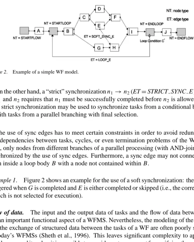
Figure 2. Example of a simple WF model.
• On the other hand, a “strict” synchronization n1→n2(ET=STRICT SYNC E ) between n1and n2requires that n1must be successfully completed before n2is allowed to start.
A strict synchronization may be used to synchronize tasks from a conditional branching with tasks from a parallel branching with final selection.
The use of sync edges has to meet certain constraints in order to avoid redundant con- trol dependencies between tasks, cycles, or even termination problems of the WF. In any case, only nodes from different branches of a parallel processing (with AND-join) may be synchronized by the use of sync edges. Furthermore, a sync edge may not connect a node from inside a loop body B with a node not contained within B.
Example 1. Figure 2 shows an example for the use of a soft synchronization: the task H is triggered when G is completed and E is either completed or skipped (i.e., the corresponding branch is not selected for execution).
Flow of data. The input and the output data of tasks and the flow of data between them are an important functional aspect of a WFMS. Nevertheless, the modeling of the data flow and the exchange of structured data between the tasks of a WF are often poorly supported in today’s WFMSs (Sheth et al., 1996). This leaves significant complexity to application developers, and it makes it impossible to provide system support for verifying the correctness of a data flow schema or for adjusting it when structural changes are applied to a WF. In our model, the exchange of data between tasks is based on global WF variables: a WF schema is associated with a set of data elements D where each element d∈ D has a unique identifier i dd and a domain domd. The data flow between tasks is defined by connecting their parameters with elements from D. For simplification, the input (output) parameters of the WF schema are logically treated as the output (input) parameters of its start (end) node.
In practice, there are often great differences in the format and in the representation of data which is the output of one task and the input to another. In order to avoid hard-wired adjustments within task modules, each task node n ∈ N can be associated with a set of so-called auxiliary services Sn. The execution of these services is closely connected to the execution of the task. An auxiliary service s∈ Sn:= Snprec∪Snsuccis either triggered when n is started (s∈Snprec) or when it is terminated (s∈Snsucc), and it therefore does not appear as a separate work item in any worklist. Services from the set Snprec may also be used to
request incomplete or missing input data of a task from the user initiating it, which has turned out to be important in our context (see Section 3). Furthermore, a task n (also the application program associated with it) may only be executed after all services from Snprec have been successfully completed. On the other hand, if a task fails or if it is undone, the effects of its associated services on global data elements are undone as well.
Definition 1 (Data flow schema). Let (N , E ) be the control flow graph of a WF schema P and let D denote a finite set of data elements associated with P. Let further PARS(X)denote the set of parameters associated with the task or the service X [PARS(X):= InPARS(X)∪ OutPARS(X)]. A data link df between a parameter pardfand a data element ddfis then described by the 4-tuple:
df =(ddf,ndf,pardf,access modedf) with
ddf∈ D,ndf∈ N ∪ S Ã
S := [
n∈N
Sn
!
,pardf,∈PARS(ndf), access modedf∈ {read,write}
The set of all data links DF, connecting task or service parameters with global data elements from D, is called the data flow schema of P.
The data links connecting service parameters with data elements from D form a key part of P’s data flow schema. The intuitive meaning of a link(d,n,p,read)∈DF is that the value of p∈InPARS(n)is read from d when the task n is started. On the other hand, the data link(d,n,p,write)expresses that the value of the output parameter p∈OutPARS(n) is written into d after the successful completion of n. In Section 2.3 we introduce properties for the correctness of a data flow schema; these properties constitute the basis for detecting possible exceptions resulting from a change and for adjusting the data flow schema when the WF is restructured.
With respect to data management we follow an approach similar to that described in (Reuter and Schwenkreis, 1995). When a task (or service) updates a data element d, its current value is not overwritten. Instead a new version is created, which may be accessed by succeeding tasks and services. This allows us to restore previous values of data elements in case of a partial rollback, and it makes it possible for tasks from different branches of a parallel processing (with OR-/AND-join) to work on different copies of the same data element d.
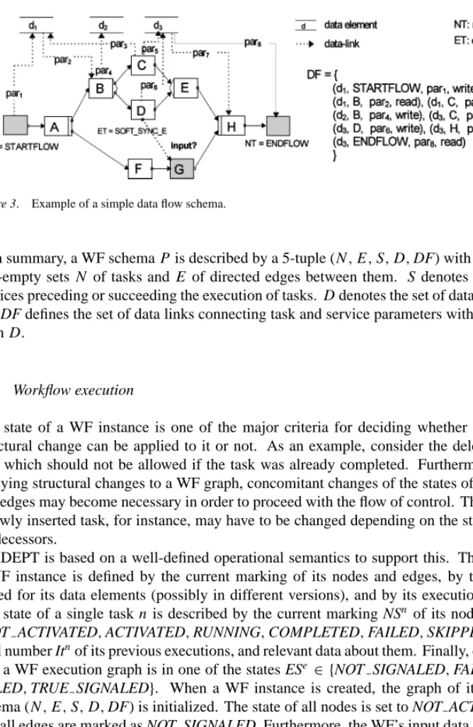
Example 2. An example for a simple data flow schema is depicted in figure 3 [Note, that the output parameter (input parameter) of the start node (end node) corresponds to the input parameter (output parameter) of the WF]. Assume that G has read access to the data element d1Although the task C may write d1before G is started, this value would not be visible to G. G may only access that value of d1written by the start node of the flow. Generally, a task may only read those values of a data element which have been written by a task or by a service preceding it in the flow of control.
Figure 3. Example of a simple data flow schema.
In summary, a WF schema P is described by a 5-tuple (N,E,S,D,DF) with finite and non-empty sets N of tasks and E of directed edges between them. S denotes the set of services preceding or succeeding the execution of tasks. D denotes the set of data elements and DF defines the set of data links connecting task and service parameters with elements from D.
2.2. Workflow execution
The state of a WF instance is one of the major criteria for deciding whether a specific structural change can be applied to it or not. As an example, consider the deletion of a task which should not be allowed if the task was already completed. Furthermore, after applying structural changes to a WF graph, concomitant changes of the states of its nodes and edges may become necessary in order to proceed with the flow of control. The state of a newly inserted task, for instance, may have to be changed depending on the states of its predecessors.
ADEPT is based on a well-defined operational semantics to support this. The state of a WF instance is defined by the current marking of its nodes and edges, by the values stored for its data elements (possibly in different versions), and by its execution history.
The state of a single task n is described by the current marking NSn of its node(NSn ∈ {NOT ACTIVATED,ACTIVATED,RUNNING,COMPLETED,FAILED,SKIPPED}), the total number Itnof its previous executions, and relevant data about them. Finally, each edge e of a WF execution graph is in one of the states ESe ∈ {NOT SIGNALED,FALSE SIG- NALED,TRUE SIGNALED}. When a WF instance is created, the graph of its starting schema (N,E,S,D,DF) is initialized. The state of all nodes is set to NOT ACTIVATED, and all edges are marked as NOT SIGNALED. Furthermore, the WF’s input data are stored in the corresponding data elements.
When the WF is started, the start node of its graph is marked as COMPLETED, and its outgoing control edge is set to TRUE SIGNALED. Each time an edge n1 → n2 (of arbitrary type) is marked, the state of its destination node n2 is reevaluated according to the execution rules defined by ADEPT. Executions rules describe the conditions un- der which a node may be activated, i.e., routed to the corresponding worklists. If the
Figure 4. Application of execution and signaling rules in connection with a loop.
node n2 corresponds to an AND-join, for instance, it is set to the state ACTIVATED if the following conditions are met: n2is marked as NOT ACTIVATED and all ingoing con- trol edges(ET=CONTROL E)are marked as TRUE SIGNALED. Furthermore, all sync edges n→n2,n∈N with ET=STRICT SYNC E must be marked as TRUE SIGNALED, and all sync edges n→n2,n∈N with ET =SOFT SYNC E must be marked as either TRUE SIGNALED or FALSE SIGNALED (see Section 2.1). Corresponding execution rules exist for all node types of a WF (incl. the start and the end nodes of loops).
The completion of a task leads to the signaling of its outgoing control as well as of its outgoing sync edges. The marking of edges follows well-defined signaling rules, which are based on the operational semantics of the different control structures. Upon successful com- pletion of an AND-split node, for example, all outgoing edges are set to TRUE SIGNALED.
This, in turn, may trigger the activation of succeeding tasks, and so on. On the other hand, a task is skipped if it cannot be activated anymore. That is the case, for example, if the task belongs to a branch of a conditional branching that has not been chosen for execution, or if an ingoing sync edge of the task (with ET=STRICT SYNC E ) has been marked as FALSE SIGNALED. When a task node is marked as SKIPPED, its outgoing edges are set to FALSE SIGNALED, which may lead to the skipping of succeeding nodes.
Finally, a WF instance terminates successfully when the ingoing control edge of its end node is set to TRUE SIGNALED. We omit further details and present two examples instead.
Example 3. Figure 4 shows the use of the execution and signaling rules in connection with a loop. After E was completed and the loop condition C was evaluated to TRUE, the loop edge is set to TRUE SIGNALED (see figure 4(a)). This, in turn, triggers the execution of the start node of the loop, whereupon the states of all nodes and edges of the loop’s body (incl. the loop’s end node and the loop edge) are reset and C is activated (see figure 4(b)).
Example 4. As a second example, consider figure 5(a). Assume that upon receiving a node termination event from B its outgoing control edge B → C signals TRUE and the edge B → D signals FALSE. This, in turn, leads to the reevaluation of the nodes C and D, which are activated respectively skipped. After skipping D, its outgoing control as well
Figure 5. Synchronizing nodes from different branches of a parallel processing.
as its outgoing sync edges are set to FALSE SIGNALED. Consequently, the state of G is reevaluated, and it is set to ACTIVATED (see figure 5(b)).
2.3. Correctness and consistency properties
As motivated in Section 1, formal criteria are needed to identify the possible exceptions resulting from a structural WF change and to provide support for handling them. In this section we give an overview of some of the correctness properties defined by ADEPT. We focus on the flow of data. Properties regarding the correctness of the control flow are only sketched at the beginning of this section.
Flow of control. A control flow graph(N,E)must meet certain constraints in order to ensure the correct execution of the WF at run-time. Each node n ∈ N must be reachable from the WF’s start node. That is, there is a valid sequence of signaling events leading from the initial marking of the WF graph to the activation of n (see Section 2.2). Furthermore, we require that from every reachable state of the WF a final state can be reached, i.e., there is a valid sequence of signaling events leading from the current marking of the WF graph to the activation of its end node. For non-cyclic WF graphs, which are based on task sequences and symmetrical branchings, these properties are satisfied by construction. This does not always apply to a WF graph whose control structures contain backward or sync edges. For example, the use of sync edges should not lead to cycles or termination problems of the flow. The presentation of conditions under which a graph(N,E)satisfies these properties and algorithms for their analysis are outside the scope of this paper.
Flow of data. In the following, we simplistically assume that for the correct execution of an action A (i.e., a task program or an auxiliary service assigned to a task) all input parameters must be supplied, and that after its successful completion all output parameters are written. ADEPT imposes a set of restrictions which govern the nature of a correct data flow schema. For each data link d f ∈DF (cf., Definition 1) the domains of ddfand pardfmust be type compatible. In addition, each parameter of an action must appear in exactly one data link d f ∈DF2. In order to avoid the invocation of actions with missing or incomplete input data the following constraint has to be added:
Rule DF-1. Let P=(N, E, S, D, DF) be the schema of a WF. For n ∈ N ∪S let Vn denote the set of all valid action sets (incl. tasks from N as well as services from S) whose elements precede n in the flow of control and which are completed before n is started. For n∈ N∪S,d ∈ D we then require:
Reads(n,d)⇒(∀V ∈Vn:∃n∗∈V : Writes(n∗,d))
The predicate Reads(n,d)(Writes(n,d)) expresses that an input parameter (an output pa- rameter) of n∈N∪S is connected to d by a data link d f ∈DF.
This rule ensures that all input parameters of an action are supplied before it may be executed. Trivially, for a given task n ∈ N,NTn 6= STARTFLOW which reads a data element d, the rule DF-1 is satisfied if d is written by the start node of the WF, or if it is written by a preceding auxiliary service s ∈ Sprecn . Furthermore, this rule guarantees that the output parameters of a WF (i.e., the input parameters of its end node) are completely supplied. In order to avoid unintended lost updates of data elements a second constraint has to be made, which we describe only informally here. For details the interested reader is refered to Appendix A.
Rule DF-2. Tasks from different branches of a parallel processing (with AND-join) are not allowed to have write access to the same data element, unless they are synchronized by a sync edge.
Write-after-write conflicts might also occur if two succeeding tasks have write access to the same data element and no read access occurs between them (see Appendix A). In (Hensinger, 1997) we present an algorithm for checking the correctness of a data flow schema with respect to the rules DF-1 and DF-2. The algorithm makes use of the sym- metrical structuring of WF graphs, but it considers synchronizations between tasks from parallel branches as well. For a basic understanding, however, an example is more suitable.
Example 5. In the WF graph depicted in figure 3, G may read the data elements d1and d2, but it is not allowed to read d3; d3is not written within all task sets of VG = {{STARTFLOW, A,B,D,F},{STARTFLOW,A,B,F}}. The task H , however, may read the data elements d1, d2, and d3as each of them is written within all task sets from VH = {{STARTFLOW,A, F,G,B,C,E},{STARTFLOW,A,F,G,B,D,E}}(cf., rule DF-1). G would not be allowed to write d3as this data element may be written by the concurrent task C (cf., rule DF-2).
Of course, the constraints upon which the definitions of the rules DF-1 and DF-2 are based must be relaxed in several respects. In our current implementation we follow a more flexible approach that distinguishes between optional and mandatory task parameters. Such extensions are important as not always all input parameters of a task are necessarily required for the correct processing of the task program. We further distinguish between parameters that can be supplied by a corresponding auxiliary service and those that cannot. We enrich interface descriptions with semantic information about parameters, and we provide support for referenced data (e.g., documents or database objects). Finally, concurrent write opera- tions to the same data element must be allowed under certain conditions (e.g., in connection
links connecting its output parameters with elements from D may lead to lost updates and therefore to the violation of rule DF-2. We will come back to this in Section 3.
2.4. Adequacy of the ADEPT model
At first glance, the ADEPT model seems to be somewhat limited when compared to other WF models. These structural limitations are deliberated, as they offer advantages in several respects: The use of symmetrical control structures provides the basis for a syntax-driven design of WF’s (cf., Kirsch, 1996) and for an efficient analysis of structural properties of a BP model (cf., Hensinger, 1997). We believe that this is crucial for the support of dynamic WF changes, especially if we want to ensure that applied changes are correct. In our experience, ADEPT offers a good compromise for the trade-off existing between the expressive power of a WF model on the one hand, and the complexity of model checking on the other hand. With respect to clinical BPs (by nature these processes are probably much more complex than the BPs found in many other application areas) it has proven that the modeling power of ADEPT is adequate. Note, that for the specification of more complex BPs, sync edges, failure edges, or null tasks (cf., Section 3) are very helpful. In addition, we are working on extensions of the ADEPT WF model (e.g., regarding concepts for the support of time and time dependencies) which will further increase its modeling power.
3. Dynamic structural changes of workflows
Based upon the ADEPT model we have developed a set of operations (ADEPTflex) which serves as the framework for dynamic structural changes of WFs. The main emphasis in designing these operations was put on correctness and consistency issues: The application of a change operation to a specific WF instance must result in a WF with a syntactically correct schema and with a “legal” state, i.e., the change should not cause inconsistencies and run-time errors. Furthermore, the set of change operations should be complete and minimal in the sense of being able to realize each possible form of correct and consistent restructuring of a WF graph—with “minimal” we mean, that the number of change operations needed to achieve completeness should be kept as minimal as possible. Other design goals, which we do not discuss in detail in this paper, concern efficiency and security issues as well as ease of use.
In summary, ADEPTflexcomprises operations for inserting tasks as well as whole task blocks into a WF graph, for deleting them, for fast forwarding the progress of a WF by skipping tasks, for jumping to currently inactive parts of a WF graph, for serializing
tasks that were previously allowed to run in parallel (and vice versa), and for the dynamic iteration and the dynamic rollback of a WF respectively of a WF region (incl. the undoing of temporary changes). These operations, in turn, provide the basis for implementing higher- level operations such as the replacement of a certain WF region by a new one. The insert operation shall serve as an illustrative example, and it will be discussed in more detail in Section 3.1. The other operations are sketched in Section 3.2.
3.1. Dynamic insertion of tasks
The addition of a new task to a WF during its execution may become necessary due to several reasons. The support of dynamically evolving WFs, unplanned events and missing or incomplete data name a few examples. The dynamic addition of a task to a WF is somewhat comparable to the addition of a new procedure to a program in the midst of its execution. When a task is inserted into a WF graph, new nodes and edges (including data links) must be added while maintaining the correctness and consistency of the WF.
Current state-of-the-art systems do not provide a sufficient level of flexibility and consistency with respect to this operation. Typically, they allow the addition of an activity only upon completion of a task and before the activation of its successors (e.g., Hsu and Kleissner, 1996; Casati et al., 1996; Vogel and Erfle, 1992). Issues concerning data integrity are mostly ignored, leading to the problems mentioned in the introduction section. For the flexible support of BPs a more generic approach is required. Generally, it should be possible
• to add new tasks or even premodeled task blocks to a WF at any point of time during its execution
• to synchronize the execution of an inserted task with the execution of other tasks from the WF graph
• to insert tasks into WF regions which have not yet been entered
• to dynamically map the parameters of the added task to existing or to newly generated data elements
There is no problem to provide an operation for inserting a new task as a direct predecessor (or successor) of a given node, for adding a task as a new branch between a split node and its corresponding join node, and so on. However, this would not yield to a satisfactory solution, as it does not reconcile with our design goals minimality and ease of use. Supporting the dynamic addition of tasks raises the challenge to find a single, generic operation that is complete in the sense of being able to realize each possible form of insertion. Obviously, the addition of a task as a direct successor of another task is too weak to meet the requirements presented above. We therefore follow a more generic approach: a new task X , together with associated services SX, data elements DX, and data links DFX, may be inserted into the graph of a WF instance by synchronizing its execution with two node sets Mbeforeand Mafter: The execution of X is triggered as soon as all tasks from the set Mbeforeare either completed or cannot be worked on anymore, i.e., the tasks defined by Mbeforedelay the execution of X . This allows us to synchronize X with (preceding) tasks from different branches of the WF graph. On the other hand, tasks from Maftermay only be activated after completing X .
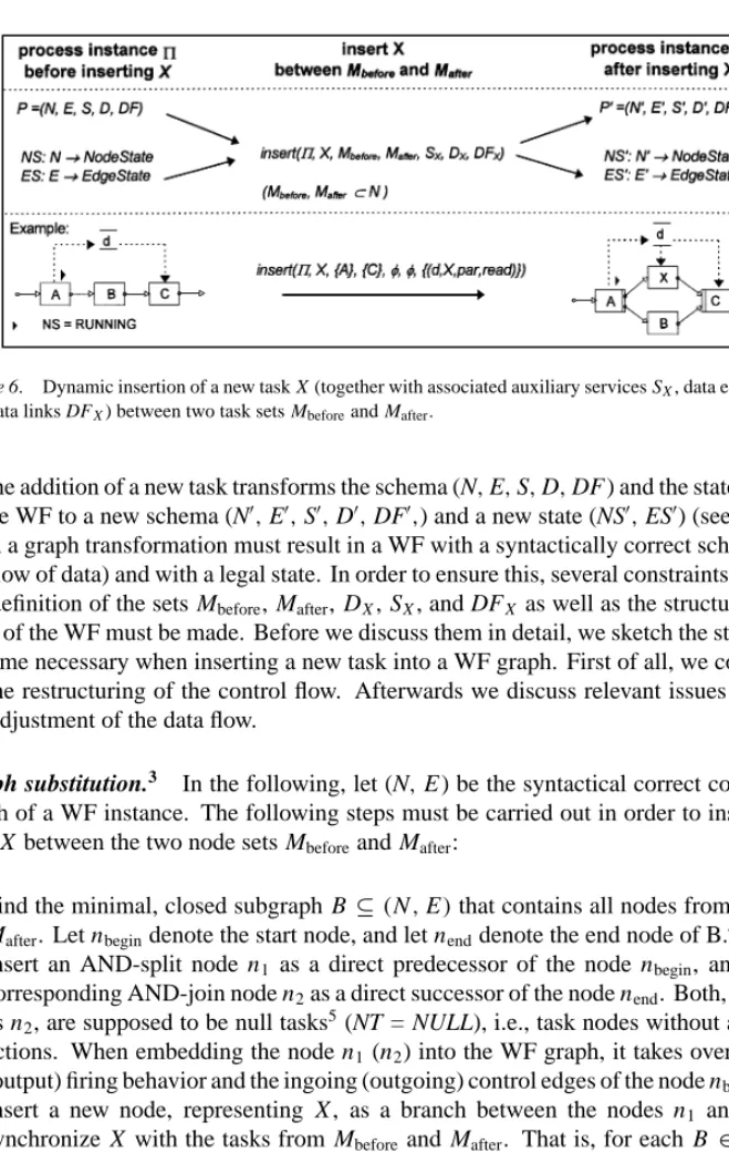
Figure 6. Dynamic insertion of a new task X (together with associated auxiliary services SX, data elements DX, and data links DFX) between two task sets Mbeforeand Mafter.
The addition of a new task transforms the schema (N,E,S,D,DF ) and the state (NS,ES) of the WF to a new schema (N0,E0,S0,D0,DF0,) and a new state (NS0,ES0) (see figure 6).
Such a graph transformation must result in a WF with a syntactically correct schema (incl.
the flow of data) and with a legal state. In order to ensure this, several constraints regarding the definition of the sets Mbefore, Mafter, DX, SX, and DFX as well as the structure and the state of the WF must be made. Before we discuss them in detail, we sketch the steps which become necessary when inserting a new task into a WF graph. First of all, we concentrate on the restructuring of the control flow. Afterwards we discuss relevant issues regarding the adjustment of the data flow.
Graph substitution.3 In the following, let (N,E ) be the syntactical correct control flow graph of a WF instance. The following steps must be carried out in order to insert a new task X between the two node sets Mbeforeand Mafter:
1. Find the minimal, closed subgraph B ⊆(N,E)that contains all nodes from Mbefore∪ Mafter. Let nbegindenote the start node, and let nenddenote the end node of B.4
2. Insert an AND-split node n1 as a direct predecessor of the node nbegin, and insert a corresponding AND-join node n2as a direct successor of the node nend. Both, n1as well as n2, are supposed to be null tasks5(NT = NULL), i.e., task nodes without associated actions. When embedding the node n1(n2) into the WF graph, it takes over the input (output) firing behavior and the ingoing (outgoing) control edges of the node nbegin(nend).
3. Insert a new node, representing X , as a branch between the nodes n1 and n2, and synchronize X with the tasks from Mbeforeand Mafter. That is, for each B ∈ Mbefore¬ {STARTFLOW}add a sync edge B→ X , and for each A∈Mafter¬{ENDFLOW}add a sync edge X → A (with ET=SOFT SYNC E).
4. Apply reduction rules and reevaluate the state of nodes and edges (see below).
As already mentioned, the application of these steps must lead to a syntactically cor- rect WF graph. To ensure this, the following constraints must be made: Firstly, for all
Figure 7. Insertion of a new task between two sets of nodes.
na ∈Mbefore, nb∈ Mafterthe node namust precede nbin the flow of control. Secondly, the region covered by the nodes between Mbeforeand Mafter(incl. nodes from these sets) may only contain complete loop control structures. Finally, to avoid the insertion of unnecessary synchronization edges, nodes from Mbefore(Mafter) should not succeed each other in the flow of control. One can show, that the insertion of a new task does not violate the syntactical correctness of the graph(N,E)and does not lead to termination problems if these condi- tions are satisfied. For further details the interested reader is refered to Appendix B. We omit them here and present an example instead.
Example 6. The example depicted in figure 7 shows how a task X is inserted between two sets of nodes. First of all, the minimal block that contains all nodes from the set{C,D,F} is determined (see figure 7(b)). In the next step, a split node n1, representing a null task, is inserted between the predecessor A and the start node B of the block. In the same way a corresponding join node n2is added. Finally, X is inserted as a new branch between n1
and n2, and it is synchronized with the nodes C,D, and F by adding the soft sync edges C → X,D→ X , and X → F (see figure 7(c)). One can easily see that the symmetrical structuring of the WF graph is preserved and that the insertion of the sync edges does not influence the termination behavior of the WF (cf., Section 2.3).
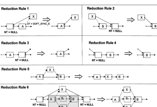
The example further shows that null tasks and sync edges might be added to the WF graph which are not necessarily required to achieve the desired execution semantics. These nodes and edges may be removed from the resulting graph by applying a set of well-defined reduction rules. Examples for such rules are depicted in figure 8. Reduction rules may be
Figure 8. Examples of reduction rules.
applied to the null tasks originating from the insertion of a task and to their direct successors and predecessors. Their application does not change the WF’s execution behavior, i.e., the set of valid task sequences remains unchanged. The effect of their application to the WF from figure 7(c) is shown in figure 7(d).
State constraints. The applicability of the insert operation depends on the state of the WF graph, too. In order to avoid the insertion of a new task as a predecessor of an already running or terminated task, we require that all elements from Maftermust be in one of the states NOT ACTIVATED or ACTIVATED. If a task n ∈ Mafter has already been activated, i.e., routed to worklists, the corresponding work items are removed from these worklists before the insertion takes place. The nodes from Mbeforemay be in an arbitrary state.
After adding new nodes and edges to a WF graph its state must be reevaluated. This reevaluation is based on the execution and signaling rules presented in Section 2.2. Whether a newly inserted task is activated immediately or not depends on the current state of the WF graph. The former is the case if at insertion time all nodes from Mbeforeare in a final state (i.e., COMPLETED or SKIPPED). Note, that the insertion of a new task does not necessarily mean that it will be activated for sure. If the task is inserted into a region of the WF graph that has not yet been entered, its execution may depend on future routing decisions.
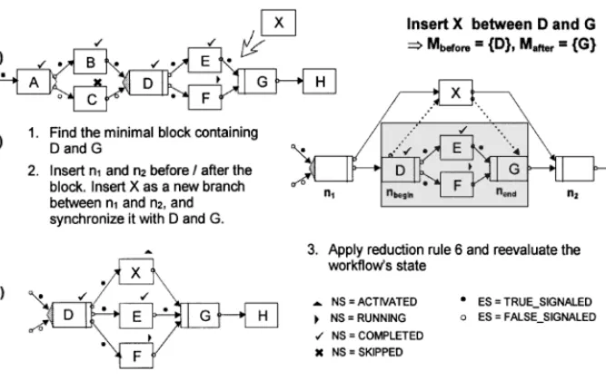
Example 7. As a simple example, consider the graph shown in figure 9, and assume that a new task X shall be inserted between the AND-split D and its corresponding AND-join G. Using the presented graph substitution steps, applying reduction rule 6 (cf., figure 8),
Figure 9. Adding a new task X between the AND-split D and its corresponding AND-join G.
and reevaluating the WF’s state, the expected result is obtained (see figure 9(c)). Note, that it is possible to add X as a new branch between D and G, although the successors of the AND-split D, the nodes E and F , have already been completed respectively started.
Furthermore, looking at the WF graph from figure 9(a), a new task X may not be inserted between the nodes D and E. In order to insert a new task between D and F , first of all, the execution of F would have to be aborted by the user.
Adjusting the data flow schema. As already mentioned, a new task X may be “plugged”
into a WF graph, together with associated data elements DX, auxiliary services SX, and data links DFX. So when a task X is added to the WF schema(N,E,S,D,DF), this does not only lead to the modification of the control flow graph(N,E)and of its state, but also it generally requires extensions of the sets D, S and DF. In any case, it must be ensured that the resulting WF schema(N0,E0,S0,D0,DF0)meets the correctness properties defined in Section 2.3.
All input parameters of the newly inserted task X must be supplied before it may be exe- cuted (cf., rule DF-1). A simple approach to achieve this would be to request the necessary input data from the user initiating X . For this, X has to be connected with a preceding provider service s (see Section 2.3), whose output parameters logically correspond to X ’s input parameters. In our current prototype implementation such a service is supported by the dynamic generation and the dynamic processing of an electronic form, which makes use of the interface description of X . The procedure depicted in Table 1 shows how the sets DX, SX, and DFX might be adapted in order to obtain a syntactically correct data flow schema satisfying rule DF-1.
Obviously, if the original WF schema (N,E,S,D,DF) satisfies the rule DF-1, this also applies to the schema(N0,E0,S0,D0,DF0)with S0 :=S∪SX, D0 := D∪DX, and DF0:=DF∪DFX. In practice, however, this simple approach would not always yield to a
create parameterpwith (Idp=Idpar∧domp=dompar∧dirp=“OUT”):
OutPARS(s):= OutPARS(s)∪ {p}
DFX:=DFX∪ {(dp, s, p, write),(dp, X, par, read)}
end
SX=SprecX := {s}
satisfactory solution, since unnecessary and redundant data entries may result in the course of a WF execution, potentially leading to data inconsistencies. For a more intelligent support, it must also be possible to dynamically map parameters of the inserted task to already existing data elements from D. This raises a variety of challenging issues with respect to dynamic parameter mapping, which can only be sketched here. First of all, the data elements CX ⊆D to which X ’s input parameters may potentially be mapped must be identified. According to rule DF-1 (cf., Section 2.3), we obtain
CX = {d∈ D| ∀V ∈VX :∃n∗ ∈V : Writes(n∗, d)}.
Example 8. As an example, consider the WF graph depicted in figure 3. Assume that a task X should be inserted between the nodes B and C. Then we obtain CX = {d1, d2}.
Note, that the definition of the set CX is independent from the state of the WF. This ensures that all data elements of CX are supplied when X is activated, independently from previously made routing decisions. On the other hand, there are scenarios in which it would be useful to relax this assumption and to consider the state of the WF as well; that is, to extend the set of data elements to which input parameters from X may be linked to
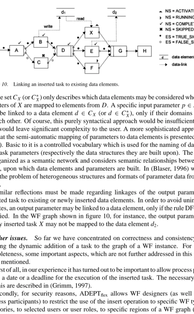
C∗X =CX ∪ {d∈ D| ∃n∗∈pred(X): NSn∗ =COMPLETED∧Writes(n∗,d)}6 Example 9. As an example, take the insertion shown in figure 9, and assume that B is the only task that writes the data element d1 ∈ D. Since B is completed at the time X is added, we have d1 ∈C∗X. Input parameters from X may therefore be potentially mapped to d1, although this data element is not contained in the set CX (see figure 10). Following this approach, it might become necessary to undo the insertion of X in case of a backward operation. As we will see in Section 4, in this context it makes a big difference whether X should be executed at most once (temporary insertion), or whether the insertion should be valid until completion of the WF ( permanent insertion).
Figure 10. Linking an inserted task to existing data elements.
The set CX(or C∗X) only describes which data elements may be considered when input pa- rameters of X are mapped to elements from D. A specific input parameter p∈InPARS(X) may be linked to a data element d ∈ CX (or d ∈ C∗X), only if their domains correspond to each other. Of course, this purely syntactical approach would be insufficient in practice and would leave significant complexity to the user. A more sophisticated approach which aims at the semi-automatic mapping of parameters to data elements is presented in (Blaser, 1996). Basic to it is a controlled vocabulary which is used for the naming of data elements and task parameters (respectively the data structures they are built upon). The vocabulary is organized as a semantic network and considers semantic relationships between the con- cepts, upon which data elements and parameters are built. In (Blaser, 1996) we also deal with the problem of heterogeneous structures and formats of parameter data from different tasks.
Similar reflections must be made regarding linkages of the output parameters of an inserted task to existing or newly inserted data elements. In order to avoid unintended lost updates, an output parameter may be linked to a data element, only if the rule DF-2 is further satisfied. In the WF graph shown in figure 10, for instance, the output parameters of the newly inserted task X may not be mapped to the data element d2.
Further issues. So far we have concentrated on correctness and consistency issues re- garding the dynamic addition of a task to the graph of a WF instance. For the sake of completeness, some important aspects, which are not further addressed in this paper, have to be mentioned.
First of all, in our experience it has turned out to be important to allow process participants to fix a date or a deadline for the execution of the inserted task. The necessary extensions for this are described in (Grimm, 1997).
Secondly, for security reasons, ADEPTflex allows WF designers (as well as selected process participants) to restrict the use of the insert operation to specific WF types or WF categories, to selected users or user roles, to specific regions of a WF graph (e.g., a task block), to selected WF states, to specific activity types or categories, or to any combination of them. Generally, also we do not require that the user who adds a task to a WF must subsequently work on it. This provides additional flexibility to process participants, as they are allowed to add tasks to a WF of which the execution may be explicitly or implicitly delegated to other process participants. This requires a powerful meta model for capturing organizational entities and relationships between them.
A new branch of a parallel branching with split node Sp Mbefore= {Sp}, Mafter = {J} and join node J
A new task without any additional synchronization Mbefore= {STARTFLOW}, Mafter= {ENDFLOW}
Finally, for the implementation of client applications and worklist handlers a correspond- ing set of (generic) API calls is offered to application programmers. The provided functions can also be used to obtain information about the context in which the insertion is applied.
Application. The insert operation described covers a broad spectrum of applications, and it allows a variety of user-friendly operations. Some of them are summarized in Table 2.
The insert operation also serves as the basis for composing higher-level operations. For example, several instantiations of the same task type (dynamic task) can be realized by the repetitive use of this change operation. Its generality also provides the basis for the ad hoc definition of WFs: a WF starts with a single stop node between the start and the end node of the WF graph, and it may be dynamically extended by the repetitive application of the insert operation presented. As a last interesting aspect, we use the insert operation for internal exception handling as well. For example, if the deletion of a task X leads to incomplete or missing parameter data of succeeding, data-dependent tasks, a corresponding provider task, taking over the data links from X , may be plugged into the graph and be synchronized with these tasks (see Section 3.2)
These examples demonstrate that our approach is able to support a large variety of different application scenarios. In the next section we sketch other change operations and some interesting issues related to them.
3.2. Overview of other change operations
As said before, ADEPTflexcomprises a set of basic change operations which allow autho- rized users to add tasks to a WF, to delete tasks from a WF, to skip the execution of tasks, to jump forward to WF regions which have not yet been activated, to serialize tasks that were previously allowed to run in parallel, and to perform backward operations on a WF graph (incl. the undoing of temporary changes). Due to space limitations we must omit a presentation of the whole set of operations here. In the following, we therefore only deal with some interesting issues related to the deletion of tasks and to the dynamic modification of premodeled task sequences.
Dynamic deletion of tasks. Individual tasks or task sequences may have to be skipped or removed when the conditions for their execution become unnecessary. Of course, the
deletion of tasks should not always be allowed. Firstly, nodes which are an integral part of the WF structure (e.g., the start node of the WF) must not be deleted at all. Secondly, WF designers may customize a WF schema in order to disallow the deletion of individual tasks or tasks from specific WF regions.
The deletion of a task X of a running WF instance is only possible, if X is either in the state ACTIVATED or NOT ACTIVATED. In the former case, the work items associated with X are removed from the corresponding worklists. Tasks in the state RUNNING,COMPLETED, FAILED, or SKIPPED may not be deleted.
Concerning the adjustment of the control flow graph, the delete operation is realized by substituting a null task (see Section 3.1) for the task to be deleted. This approach can be handled in a simple and effective manner, as the node of the deleted task and its associated (control) edges are still part of the WF structure. As we will see in Section 4, this also facilitates the undoing of task deletions.
When a task X is deleted, its associated auxiliary services and data links must be removed from the set S and from the set DF. This might lead to missing or incomplete input data of succeeding data-dependent steps and therefore to a violation of the rule DF-1 (cf., Section 2.3).
Let N∗⊂succ(X)7denote the set of tasks whose input parameters are not completely supplied due to the deletion of X . The following exception handling policies can be applied in ADEPTflexto deal with such cases and to regain a correct and consistent WF graph:
• Concomitant deletion of tasks from the set N∗, which, in turn, may require the deletion of other tasks from N (cascading delete).
• Dynamic insertion of a provider task Xproxinto the flow of control (with Mafter =N∗).
Xproxtakes over the data links of the deleted task, and it must be completed before any task of the set N∗may be triggered.
• Dynamic addition of corresponding provider services (i.e., dynamically generated forms) to the sets Snprec, n∈ N∗(see Section 3.1)—this must not lead to the violation of the rule DF-2!
• Abortion of the delete operation.
Of course, these policies may be used in combination with each other. In order to relieve users from performing the necessary adjustments of the data flow schema “manually”, ADEPT supports the specification of success dependencies between succeeding tasks. If a task X is deleted from the WF graph at run-time, all succeeding tasks which are success- dependent on X are deleted as well. This, in turn, may lead to the cascading deletion of other tasks. Concerning the flow of data this approach does not require any additional exception handling, if for each task the set of its success-dependent steps corresponds to that of its data-dependent steps. Note, that this approach is similar to the concept of spheres of control proposed in (Davis Jr., 1978; Leymann, 1995), but it is applied here to the structure of the WF.
Changing task sequences at run-time. As mentioned in the introduction section, changes of premodeled task sequences frequently become necessary in exceptional situations. Since WF designers are generally not capable to predict all possible deviations in advance,
Figure 11. Parallelization of tasks, that were previously constrained to be executed serially, due to a jump forward operation.
operations are required that allow users to dynamically skip the execution of tasks, with or without finishing them later, or to work on tasks of which the execution conditions are not yet satisfied.
Example 10. As an example, take the WF graph depicted in figure 11(a), and assume that an authorized user wants to jump forward to task G and to proceed with the flow of control at this node, although the ingoing edges of this task have not yet been marked. Assume further, that the steps D, E , and F have to be finished or worked on concurrently, but they must be completed before task J may be triggered. In order to achieve this, the WF graph must be restructured as shown in figure 11(b). Note, that this restructuring leads to the parallelization of tasks that were previously constrained to be executed serially.
Generally, it should be possible to pass the control or to jump forward to a node ntarget which may not yet have been activated (NS=NOT ACTIVATED). ADEPTflexsupports different policies for dealing with uncompleted tasks, preceding the node ntargetin the flow of control, when such a jump operation is performed:
M = {n|n∈pred(ntarget)∧NSn∈ {NOT ACTIVATED,ACTIVATED,RUNNING}}
Tasks from this set may be aborted, omitted, or as in our example be further worked on.
For the latter case, their execution must be synchronized with successors of ntarget. In our example, all tasks from M = {D,E,F}must be completed before the node nd = J may be activated.
Finally, changes of premodeled task sequences may lead to an incorrect data flow schema if no further precautions are taken. The rules presented in Section 2.3 contribute to identify