2000 Springer-Verlag London Limited
A Survey of Design Rationale Systems: Approaches, Representation, Capture and Retrieval
W. C. Regli
1, X. Hu
2, M. Atwood
3and W. Sun
21Geometric and Intelligent Computing Laboratory, Department of Mathematics and Computer Science, Drexel University.
Philadelphia, PA, USA; 2Rapid Product Development Center, Department of Mechanical Engineering and Mechanics, Drexel University, Philadelphia, PA, USA;3College of Information Science and Technology, Drexel University, Philadelphia, PA, USA
Abstract. This paper provides a survey on recent research in the area of design rationale. The study of design rationale spans a number of diverse disciplines, touching on concepts from research communities in mechanical design, software engineering, artificial intelligence, civil engineering, com- puter-supported cooperative work, and human-factors and human-computer interaction research. We focus this survey on prototype design rationale systems for these application domains, and put forward several major criteria with which to describe and classify design rationale systems, including argumentation-based, descriptive, process-based approaches.
Further, we attempt to abstract the place of systems and tools for design rationale capture and retrieval in the context of contemporary knowledge-based engineering and Com- puter-Aided Design (CAD) tools. This survey is structured around classes of fundamentally different approaches, their representation schema, their capture methods and retrieval techniques. A number of recent design rationale systems, including JANUS, COMET, ADD. REMAP, HOS, PHIDIAS, DRIVE and IBIS are analysed. We conclude with an assess- ment of current state-of-the-art and a discussion of critical open research issues.
Keywords. Design history; Design intent; Design rationale capture; Engineering design process;
Knowledge management; Software design; User interface design
1. Introduction
Design rationale is an explanation of why an artifact, or some part of an artifact, is designed the way it is [1]. Design rationale includes all the background knowledge such as deliberating, reasoning, trade-off
Correspondence and offprint requests to: Professor W. Regli, Department of Mathematics and Computer Science, Drexel Uni- versity, Korman Center, Rm 238, Philadelphia, PA 19104, USA.
E.mail: regl:@drexel.edu
and decision-making in the design process of an artifact – information that can be valuable, even critical, to various people who deal with the artifact [2–6]. These views are consistent across the whole spectrum of engineering design disciplines, from mechanical design and architecture-engineering- construction to software and user-interface design.
Usually a developed artifact is defined in terms of specifications and parameters to describe the way it works, but does not include a description of why it is designed the way it is. Design rationale is usually not documented completely, and the colla- borating work teams often need considerable amounts of communication to understand others’
work [7]. Activities to maintain and redesign the artifact require much effort to understand the pre- vious work. Many believe that keeping track of the design rationale will provide a great aid to designers:
it helps to structure design problems, and provides a basis for designers to explore more design options.
Design rationale systems can be used as a basis to discuss and reason among collaborating designers:
to record the history of design process; to modify and maintain existing designs, or design similar artifacts [8,9].
Much progress has been made on the development of design rationale approaches and tools since the early 1980s. The research has ranged from basic observations about the design process [10] to differ- ent approaches to capturing design rationale. In this previous work, basic concepts were discussed and frameworks for design rationale were proposed. A number of important prototypes have been developed, but few design rationale systems have made it into practical use in industry. To this end, the fundamental goal of this survey paper is to answer the questions:
쐌 If design rationale is useful (most agree on this
point), why are design rationale systems not in widespread use in industry?
쐌 How can design rationale systems better support engineering design?
쐌 What are the major obstacles to the creation of truly useful and usable design rationale systems?
For a more comprehensive background reference of the design rationale field, interested readers are referred to the excellent 1996 edited collection by Moran and Carroll [11], as well as discipline-specific overview papers [12,13]. Recent research has a tend- ency to combine design rationale systems with other forms of design support tools [14,15]. Lee’s [12]
recent article describes some of the major open issues in design rationale research. We present this paper as a system-centred overview, with the goal of helping current and future builders of design rationale support environments sort through the many issues of system development. Furthermore, we put forth presently outstanding issues for design rationale research and practical system deployment and use.
This survey is organised as follows. Section 2 gives the framework of the survey, basic concepts of design rationale are introduced and design rationale systems or prototypes are reviewed in chronological order and summarised. Section 3 describes basic approaches to design rationale. Section 4 describes the representation schema of design rationale sys- tems. Sections 5 and 6 describes the capture and retrieval of design rationale, respectively. Section 7 touches on some of the related research areas that support the study of design rationale. Section 8 provides brief examples of several different uses and applications for design rationale systems. In Section 9, we summarise our review, and discuss the open research issues that must be addressed to advance the state-of-the-art in design rationale systems.
2. A Framework for Design Rationale
The research on design rationale covers a large range of topics; this survey focuses on the review and analysis of existing systems and prototypes. In this context, a design rationale system intends to let designers think and discuss design within a certain knowledge representation framework.
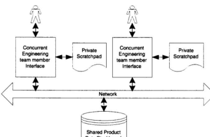
Figure 1 illustrates how a prototypical design rationale system works. Based on a representation schema, the decisions and reasoning are either recorded by designers themselves using documents,
Fig. 1. Flow of information in a design rationale system frame- work.
or captured by a design rationale system’s monitor- ing module. The capture of design rationale can occur from the design teams’ communications via Computer-Supported Cooperative Work (CSCW) tools, such as electronic mail, phone conversions, and archived design meetings and designers’ note- books. The design knowledge captured is organised by rules, which are primarily determined by a rep- resentation schema, and stored into the design rationale sytem knowledge-base – to then be used in later design activities. If a design is similar to an existing design, the design rationale for the for-
mer design can be retrieved from the design ration- ale database, providing the suggestions and ideas relevant for the current design task. Some systems (e.g. the CRACK system [16]) also include critiqu- ing tools, which are based on domain knowledge and can justify design decisions. Generally, a design rationale system is supported by knowledge-based systems and Computer-Aided Design and Manufac- turing (CAD/CAM) systems, opening up a wide range of possibilities in supporting design activities.
We break the core of our survey down based on major systems and prototypes, and examine the four following issues.
Approaches to developing design rationale systems.
Since the first approach to design rationale was proposed in 1970 [17], various other approaches have been developed. The main approaches are pro- cess-oriented and feature-oriented. In fields with a relatively high degree of standardisation, the feature- oriented approach is frequently used. Feature- oriented approaches focus on the representation of artifacts and the body of established rules governing the design process. In dynamic design domains, in which accepted design principles may not be well established, the process-oriented approach is often used to create a historical representation of the design process [2,3]. The integration of design rationale systems with other design support tools (knowledge-based, CAD and collaborative work) also influences the approach.
Representation schema for design rationale. A design rationale representation explicitly documents the reasoning and argumentation occurring in design [5]. The representation determines the methods used to capture and retrieve the design rationale, so it is important to select an appropriate representation schema.
Argumentation-based design rationale is a mainly representational approach which uses a semi-formal graphical format [2] for laying out the structure of arguments. It uses a node-and-link representation, which means it uses typed links to interconnect typed nodes [18]. A node represents a component, while a link represents a relationship. With argumen- tation, designers can easily maintain consistency in decision-making, keep track of decisions, and com- municate about design reasoning with each other.
The most common argument structures for selecting and organising information are IBIS, PHI, QOC and DRL.
Some systems use a descriptive approach [3] to represent design rationale, which records the history
of design activities, work flow and communication between designers [18]. More specifically, it records what decisions are made, when they are made, who made them, and why [18]. This approach is used in dynamic design domains, in which the problems are vague and the solution technology is poorly understood, and therefore little or no standardisation of designed artifacts exists. The descriptive approach emphasises minimising the intrusion to designers by making design rationale capture as transparent as possible. This makes re-usability of the design rationale incidental [3].
Capture of design rationale. In a design process, design rationale is captured by recording reasoning, decisions, options, trade-offs, etc., and constructing a formal [9] or semi-formal structure [2] so that the design rationale can be used in the decision-making process during design.
Determining what information to capture during design, and how to capture it, is a fundamental problem many have tried to address. Gruber [19]
proposed that rationale support tools should focus on capturing the information that is used to answer designers’ questions, as well as data that might be used to infer answers to later questions. The depen- dency relations among the data and information are very useful, and should be captured as well. In this environment, rationale explanations are constructed in response to information requests, from back- ground knowledge and information captured during design.
Applying this philosophy in a design environment using traditional CAD drawing tools, which are focused on detailed design and only capture data about the physical or logical aspects of an artifact, the design rationale support tools should capture information such as the intended behaviour or func- tion of a device, and the justification for design decisions [4].
The design rationale capture process generally consists of two steps: knowledge recording and design rationale construction. The first involves capturing as much raw information as possible during the design process. The second step is the extraction, organisation and storage of rationale knowledge, which is based on the design rationale representation schema and constraints in the design domain. We observed that the recording and con- struction processes have been implemented in design rationale systems through both automatic capture approaches and those requiring user-inter- vention (in which designers are required to input
or record the design discussions, decisions and reasonings themselves).
Retrieval of design rationale. The retrieval of design rationale is determined by the representation schema and the requirements of the engineering domain for which the knowledge is being used. At each differ- ent design stage, there are various purposes for accessing design rationale: to answer a user query, to show the logical aspects of an important issue, to monitor design process, or to get a document about the designed artifact [31,27,33]. Different access strategies are needed to help users with differ- ent purposes. The retrieval of design rationale can be active or passive. It is desirable that some design rationale retrieval be triggered automatically accord- ing to the design context [24].
Given a representation schema, tools supporting functions such as navigation by designers [16] and retrieval strategies [27] can be implemented. The integration of design rationale systems with other design support systems can greatly improve the retrieval of design rationale. The retrieval of design rationale in such systems is usually involved in the design reasoning process, and supported by knowledge-bases in the design support systems.
A design rationale system is not effective as a standalone system. Together with other design sup- port systems, such as CAD or Computer-Aided Software Engineering (CASE) tools, it contributes to the design process by providing designers with a knowledge representation framework, as well as tools to capture design rationale, design reasoning and communication during the design process. Ide- ally, such systems can transform raw design ration- ale and design history into knowledge for later re- use – providing facilities to retrieve design rationale when needed for review, maintenance or redesign.
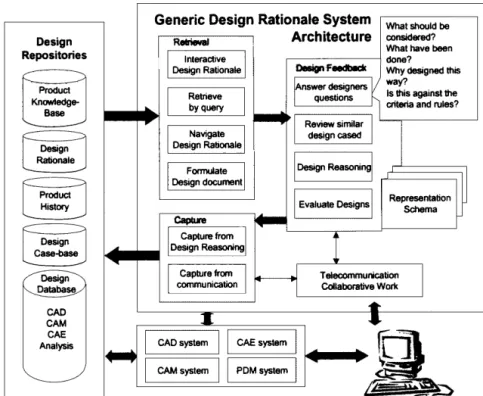
Figure 2 shows the architecture of a general design rationale system, generated from our survey by syn- thesising the functions of different systems. The design rationale systems or prototypes that we reviewed generally did not include all of the features indicated in the diagram.
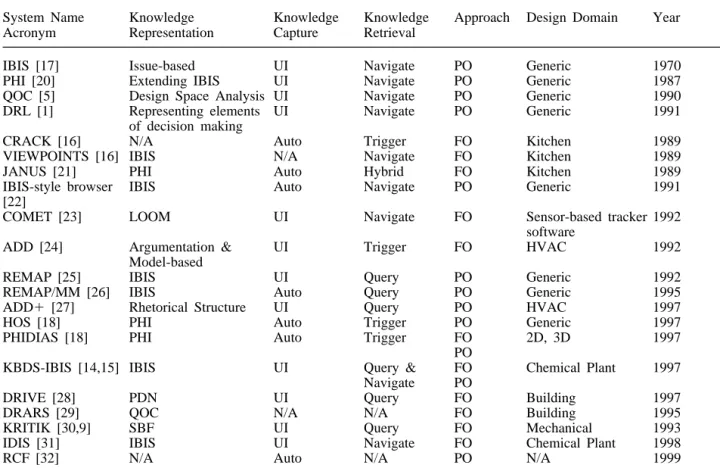
To provide a general view of the development of the research area, we list the design rationale sys- tems reviewed (in chronological order) according to the catalogue described above in Table 1. Each system is described in five dimensions: knowledge representation, capture, retrieval, approach and the application domain. The following sections will con- centrate on a detailed discussion of the systems in the table.
3. Approaches to Building Design Rationale Systems
At different stages of the design process of an artifact, design can be more process-oriented or more feature-oriented. At the initial design stage, as the design progresses from the requirements to a conceptual design, there are many discussions con- cerning the requirements (which may not be well specified), and much exploration of options and trade-offs since there may be no fixed solution path [34]. This design process is more dynamic, with knowledge organised according to design progress, so the approach of design rationale at this stage is more process-oriented. At the detailed design stage or in routine design, design process is more con- strained by the rules in the field or domain knowl- edge, since it is feature-oriented, [24,32], in which features could be function, performance, design, manufacture or implementation. These differences in the characteristics of the two different phases of design naturally lead to the two different approaches to design rationale.
3.1. Process-Oriented Approaches
Process-oriented design rationale systems emphasise the design rationale as a history of the design pro- cess. Process-oriented design rationale has been most often used in domains where the problems are vague, the solution technology is poorly understood, or both, and in which there is little or no standardis- ation of designed artifacts [3]. Unlike feature-ori- ented systems, which construct design rationale as a logical structure, design rationale is merely descriptive in a process-oriented system. Most exist- ing design rationale systems are process-oriented, with issues, options and arguments captured and organised according to the design progress.
This approach originated from the Issue-Based Information System (IBIS) framework for argumen- tation [17]. A number of other frameworks have been developed since then, including DRL [1] and PHI [20].
The representation schema of this kind of ration- ale is generally graph-based, using nodes and links, with nodes indicating issues (questions), positions (options) and arguments, and links indicating the relationships among the nodes. This kind of rep- resentation schema provides a flexible structure and great convenience in recording design rationale from communications of design progress. This is especially true for multimedia communications, since
Fig. 2. The general architecture of a design rationale system.
multimedia nodes could be included as part of the design schema [26,18].
Figure 3 shows an example of the process-based approach to design rationale. In this example, a material handling system is being planned for a manufacturing plant in design. At this initial design stage, there is only a functional specification, with no restrictions on the step-by-step evolution of the design. With the process-based approach to design rationale, the step-by-step reasoning is captured and represented according to different tasks in the func- tional specification. An IBIS schema is used here for design rationale representation.
The challenge with this approach is to convert the captured information into structured design rationale – to create links among nodes – to make the information accessible. A number of approaches have been used to create links among nodes: PHID- IAS [18] links the nodes by authoring and indexing;
REMAP/MM [26] supports hyper-links among design deliberation records and multimedia objects.
This conversion process presents a large overhead to the design rationale maintainer (a smart computer or a patient human being). Another method to organize the recorded information is incremental formalisation, described in Shipman and McCall [35].
Once the nodes are linked, design rationale reuse becomes a matter of retrieval of the knowledge. The
rationale could be viewed by traversing from one node to another by way of links, or be retrieved in response to queries. There are a number of tech- niques to deal with this; more detailed information on retrieval is given in Section 6.
The process-oriented approach to design rationale helps designers by providing descriptive history information, to answer questions such as who, why, what and when. Currently, it is not easy to translate this into representations that can be understood and processed by computers, so this approach provides support to the design process only when designers access and understand it [21].
3.2. Feature-Oriented Approaches
A feature-oriented approach starts from the design space of an artifact, where the rules and knowledge in the specific domain must be considered in design decision making. A design decision not supported by the rules of knowledge needs to be confirmed, so it will cause a revision of the rules and knowledge in the domain [24].
A feature-oriented system is usually developed in a task specific context using an empirical study.
Some models are extended from generic Design Decision Support (DDS) systems by adding primi- tives to explicitly represent design process. Gener-
Table 1. Table of prototype design rationale systems.
System Name Knowledge Knowledge Knowledge Approach Design Domain Year
Acronym Representation Capture Retrieval
IBIS [17] Issue-based UI Navigate PO Generic 1970
PHI [20] Extending IBIS UI Navigate PO Generic 1987
QOC [5] Design Space Analysis UI Navigate PO Generic 1990
DRL [1] Representing elements UI Navigate PO Generic 1991
of decision making
CRACK [16] N/A Auto Trigger FO Kitchen 1989
VIEWPOINTS [16] IBIS N/A Navigate FO Kitchen 1989
JANUS [21] PHI Auto Hybrid FO Kitchen 1989
IBIS-style browser IBIS Auto Navigate PO Generic 1991
[22]
COMET [23] LOOM UI Navigate FO Sensor-based tracker 1992
software
ADD [24] Argumentation & UI Trigger FO HVAC 1992
Model-based
REMAP [25] IBIS UI Query PO Generic 1992
REMAP/MM [26] IBIS Auto Query PO Generic 1995
ADD⫹ [27] Rhetorical Structure UI Query PO HVAC 1997
HOS [18] PHI Auto Trigger PO Generic 1997
PHIDIAS [18] PHI Auto Trigger FO 2D, 3D 1997
PO
KBDS-IBIS [14,15] IBIS UI Query & FO Chemical Plant 1997
Navigate PO
DRIVE [28] PDN UI Query FO Building 1997
DRARS [29] QOC N/A N/A FO Building 1995
KRITIK [30,9] SBF UI Query FO Mechanical 1993
IDIS [31] IBIS UI Navigate FO Chemical Plant 1998
RCF [32] N/A Auto N/A PO N/A 1999
Capture Method: User-Intervention (UI) or Automatic (Auto) Representation Method: Feature-Oriented (FO) or Process-Oriented (PO) Retrieval Method: Navigate, Query, Trigger or Hybrid.
Fig. 3. An example of process-based approach: the planning of a material handling system for a manufacturing plant.
ally, these kinds of systems contain domain knowl- edge-bases, which can be used to support automated reasoning. CRACK is a typical feature-oriented sys- tem [16]; its detailed description can be found in the following sections.
In a feature-oriented design rationale system, existing knowledge-bases usually support the gener- ation of design rationale, so representations of design rationale are usually more formal than in process- oriented systems. In some systems, the design rationale is represented with links to the existing knowledge-base. The retrieval and reuse of design rationale is very natural in the design process of later artifacts. An example model is GTMD [36], which is used to structure the acquisition process
within DESIRE, a formal framework for compo- sitional modelling.
With this approach, design rationale systems are usually included in the design systems. This helps designers by storing design rationale in a formal format which can be processed automatically, so it can provide active support to design or redesign processes such as the evaluation of design decisions and conflict resolution [28].
While the feature-oriented design rationale approach provides active support to design activities, it has the limitation that only part of design rationale (i.e. how the artifact designed satisfies the requirements) can be handled: other parts (i.e.
option-exploration, trade-off, who, when, why, etc.) cannot be handled with this approach [30].
Combinations of both of these approaches have been proposed to help overcome their individual limitations. Systems with such a hybrid approach not only provide logical structure for design ration- ale, but also record the history of the design process.
KBDS-IBIS is such an example [14].
3.3. Integration with Other Design Support Systems
A design rationale system is usually positioned as a technology to augment Computer Aided Design (CAD) and other engineering activities. In this way, it is not intended as a stand-alone system. Its smooth integration with other design support systems affects its effectiveness and efficiency. Figure 2 gives a general view of the integration of design rationale systems with other systems.
There is a trend towards tight integration of design rationale tools with other design representations [2], with the design rationale system being treated as an extension of the design system. Design rationale systems integrated with commercial CAD system have been extensively reported [14,31,32,27,24,37, 26,18]. In some of these systems, the integration was achieved by the combination of design rationale system with knowledge-based design decision sup- port systems [31,27,37,26]. To integrate design rationale tools with design systems, there should be an integration of representation schemas. This improves the design system, makes the implemen- tation of design rationale easier [9], and makes the capture and retrieval of design rationale driven by implementation concerns. The integration of design rationale with Computer Supported Cooperative Work (CSCW) and telecommunications was reported in PHIDIAS [26,18].
Sections 4–6 give a more detailed discussion on representation schema, capture and retrieval.
4. Representation Schemas
Due to the increasing complexity of computer sys- tems and demand for higher reliability, there is a growing interest in developing design systems to help designers record and re-use design rationale.
Especially for the design and maintenance of large systems (such as software systems), the capture and re-use of design rationale information system can be essential over the life-span of the product.
Designing an artifact involves considering many alternatives – where one must address, evaluate, and ultimately accept or reject each alternative. A design rationale system needs to record the analysis of the various alternatives so that designers can easily make their decision; after designing, the rationale for a design should be kept for future use. How to organise this enormous amount of diverse material, and build it into a usable structure, is a critical issue [2]. A good representation schema is vital to
enabling effective design and reuse. Much attention has been focused on developing methods, notations and tools for recording rationales, the space or history of arguments surrounding the actual decision made as development progress is represented. An overview of some of the most prominent techniques is given in the following sections.
4.1. The Issue-Based Information System (IBIS)
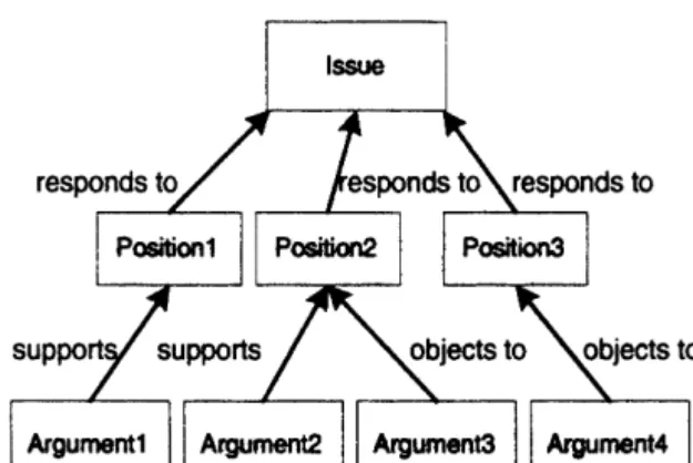
The Issue-Based Information System (IBIS) uses an issue-based approach that has been used in architec- tural design, city planning and public-policy dis- cussion. The key issues of IBIS are usually articu- lated as questions, with each issue followed by one or more positions that respond to the issue. Each position can potentially resolve or be rejected from the issue. Arguments either support or object to a position. Figure 4 shows the relationship among three elements in IBIS. An IBIS-style browser [22]
is the implementation of a merged issue-based and truth-maintenance [38] dependency structure. Such browsers use a graphical shorthand to represent node types and link types in a graph-based structure.
Issues, positions and arguments are the main compo- nents captured in the graph. One characteristic of such a system is that it can provide immediate feedback to designers by indicating the belief status of various issues (via colour or other notations on the nodes).
The Representation and Maintenance of Process knowledge (REMAP) system [25] uses the Telos language to represent knowledge, and is also based on the Issue Based Information Systems (IBIS) method. The history about design decisions in the development life-cycle is called process knowledge.
Much of this knowledge, involving the deliberation on alternative requirements and design decision, is
Fig. 4. The relationship of issue, position and argument.
lost in the course of designing and changing such systems. REMAP records the argumentation related to deliberations and solves the process knowledge loss problem. As the deliberation proceeds among designers during the design process. REMAP lists various issues, such as a problem, a concern or a question that requires discussion for the problem solving to progress; positions (alternatives) for solv- ing each issue are responded using a process model window, each of these positions has different sup- porting arguments, each of which in turn is sup- ported by assumptions. Issues are resolved by mak- ing a decision to select a position, thereby leading to a constraint that needs to be satisfied by design objects. Therefore, process knowledge is related to the objects that are created during the requirements engineering process.
Researchers have recognised that an explicit rec- ord of design rationale is an important requirement for effective design support. As computer systems supporting all aspects of the design process evolved, many have pursued integrating the record of ration- ale with the history of the evolution of the design artifact [39,40]. An integration of these two disjoint data models could bring many benefits for design, such as improved documentation of the design pro- cess and the verification of the design methodology and the resulting design artifact.
The Knowledge Based Design System-IBIS (KBDS-IBIS) [14] is the result of integrating a representation of design rationale (in the form of IBIS networks) to the design alternative history maintained by a design support system (KBDS).
KBDS-IBIS has been used in chemical process plant design, and put forward some extensions to the structure of standard IBIS networks. KBDS-IBIS introduced three new classes of object – artifacts, steps and tests. These integrate the representation of argumentation with the design process history.
KBDS-IBIS also can automatically generate two types of reports: step reports, which describe the design rationale for the evaluation of one design alternative relative to another; issues reports, describing the deliberation leading to a particular design. These record in a prescriptive fashion – allowing the design team to identify which parts must be re-designed in the light of a change in the internal assumptions, constraints or specification, or a change in any external factors affecting the design.
In an integrated and prescriptive form, KBDS-IBIS explicitly maintains the history of the design goals, decisions, justifications and assumptions coupled with the evolving description of a chemical process plant during its conceptual design.
Chung [31] described an Integrated Design Infor- mation System (IDIS) that supports the design of chemical plants. This system also places particular emphasis on supporting the design process so that the recording of design rationale may be done easily.
A commercial system from Enviros Software Sol- utions, DRAMA (Design RAtionale MAnagement), was based on the ideas of the KBDS prototype from the University of Edinburgh. It uses a graphical user interface and an object-oriented database to store and structure reasoning relating to design (http://www.enviros.com/drama/).
4.2. Procedural Hierarchy of Issues (PHI)
The Procedural Hierarchy of Issues (PHI) [20]
extends IBIS by broadening the scope of the concept
‘issue’ and by altering the structure that relates issues, answers and arguments. First, it simplifies relations among issues by using the ‘serve’ relation- ship only. Secondly it provides two methods to deal with design issues: deliberation and decomposition (i.e. to give answers to the issue or to break down the issue into a variety of subissues which in turn could be deliberated or decomposed). The prime issue is by definition the whole project. PHI avoids raising irrelevant and trivial issues [20]. Another advantage of PHI is that the issues, subissues, answers and arguments can be presented in the format of outlines, as shown in Fig. 5. Compared with IBIS, PHI provides dependency relationships between issue resolutions and considers the pros and cons of alternative answers [41]. In addition, it more completely and accurately models the task structure of the design process and the information useful for tasks [21].
VIEWPOINTS [16] is a hypertext system for argumentative kitchen design based on the PHI design methodology. It is a a tool which supports the argumentative approach within the design pro- cess. The elements of VIEWPOINTS are issues, answers, arguments and graphics. It provides a graphical interface to facilitate its use, enabling designers to do extensive browsing and make decisions.
JANUS [21] is the integration of the CRACK and VIEWPOINTS systems. CRACK [16], another computer-supported design rationale system, is a knowledge-based critic which has information about how kitchen appliances can be assembled into a functional kitchen. JANUS allows architectural and interior designers to graphically construct artifacts by direct manipulation, and at the same time receive
ISSUE:
What kind of conveyers should be used in material handling?
SUBISSUE:
1. What kind of conveyers should be used in bulk material handling?
%
2. What kind of conveyers should be used in unit material handling?
ANSWERS:
1. Gravity conveyers SUBANSWERS:
1. chutes, skate wheel conveyers 2. roller conveyers
ARGUMENTS:
1. Its advantage is low cost, relatively low maintenance, and negli- gible breakdown rate.
2. Its requirement is the ability to provide the necessary gradient in the system configureation.
%
2. Powered conveyers
%
3. Chain-driven conveyor
%
4. Power-and-free conveyers
%
Fig. 5. An example of PHI: select conveyers for material handling.
information useful to what they are doing from hypertext activated by knowledge-based agents.
From JANUS and its predecessors CRACK and VIEWPOINTS, we can see that integrated support for construction and argumentation is necessary for full support of design.
PHIDIAS [18] is a hypermedia system which is based on PHI; like other rationale representation schemes, it uses a graph-based node-link structure.
PHIDIAS represents all of its knowledge, including semi-formal rationale as well as formal represen- tations of physical objects, facts and rules, in this graph-based format. In PHIDIAS’s graphs, both nodes and links are first-class objects with prototype- based inheritance. Nodes can vary in size from a single letter to a multi-page document, with most
rationale nodes corresponding to individual words, sentences, or paragraphs. The Hyper-Object Sub- strate (HOS) [18] is another hypermedia prototype. It includes a generic view containing an argumentation structure, which uses a piece of the design and nearby discussion as an example in this structure.
4.3. Design Space Analysis
Design space analysis places an artifact in the space of possibilities and seeks to explain why the parti- cular artifact was chosen from these possibilities.
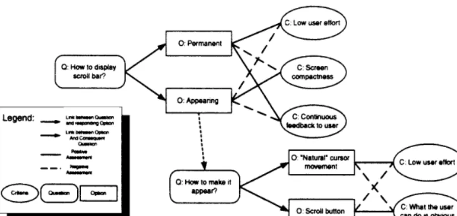
The Question, Option and Criteria (QOC) [5] is one semi-formal notation of design space analysis, which focuses on the three basic concepts indicated in
its name. The QOC representation emphasises the systematic development of a space of design options structured by questions, which is different from the IBIS-derived systems and PHI, whose purpose is to capture the history of design deliberation. QOC represents the design space using three components:
questions identify key issues for structuring the space of alternatives; options provide possible answers to the questions; criteria are the bases for evaluating and choosing from among the options.
Figure 6 presents an example of design space analysis for displaying a scroll bar. The rationale representation in QOC is created along with the descriptive representation (specification) or the arti- fact itself (prototype). In aspects of innovation and reuse, QOC has many advantages. It is relatively easy for a maintainer to create a QOC to ‘reverse engineer’ a part of a system and preserve it for future use. QOC records the exploratory activity of the design team, such as what alternatives were considered and what choices were made and why.
QOC’s graphical argumentation notation lets team users actively manage QOC recording during work, and supports the transition from expression to docu- mentation, from informal, incomplete, private ration- ale to more formal, complete, and publicly intelli- gible rationale [42].
The Design Rationale Authoring and Retrieval System (DRARS) [29] is a system that uses a variation of QOC [29]. Views, goals, alternatives, claims, questions, answers and versions are the DRARS system’s objects. The human user is respon- sible for giving descriptive and useful names to these objects.
Another way to record design rationale is by describing how an artifact serves or satisfies expected functionalities, using languages such as Decision Rationale Language (DRL) [1] or Function
Fig. 6. A QOC representation of the design space for displaying scroll bar [5].
Representation (FR) [30]. DRL is an expressive language which represents the space around decisions, which can be maintained independently or integrated with traditional design representation.
DRL was implemented in a system called SIBYL [43]. and is being used to explore various kinds of computational service over DRL structures.
Also related to QOC, [44] describes a language called TED used to represent the reasoning behind the implementation of particular features.
4.4. Functional Representations
Functional Representation (FR) [30], a represen- tational scheme, describes how the device works (or is intended to work). In the functional representation scheme, design rationale is used as an account of how the designed artifact serves or satisfies expected functionality. One can use FR to capture the causal components of design rationale. FR takes a top- down approach to represent a device: the overall function is described first, and the behaviour of each component is described in the context of this func- tion. FR encodes the designer’s account of the causal processes in the device that culminate in achieving its functions. Tasks that design rationale should be able to support are: control of distributed design activity; reassessment of device functions; generation of diagnostic knowledge; simulation and design veri- fication; redesign; and case-based design. FR pro- vides a partial rationale for choices made about components and their configuration; its limitation is that FR only captures the causal knowledge about device operation.
The Structure, Behaviour and Function (SBF) model [37] is an approach for designing devices which explicitly represents the functions of the
device (the problem), the structure of the device (the solution) and the internal causal behaviours of the device. Function can be defined as what (an object) does, behaviour as how (it) does what (it) does, and structure as what (an object) is. For example, a clock’s function is to indicate to an observer the time, its behaviour is that its hands go around with a periodicity matching the elapsing of time, and its structure is its composition of metal, plastic, glass, and so forth [45]. The structure of a device in the SBF language is represented as a schema that specifies the input behavioural state of the device. The SBF model of a device also specifies the internal causal behaviours that compose the func- tions of device substructures into the functions of the device as a whole. The functional models rep- resent design cases from which adaptation spaces are generated for solving a new design problems.
The designed products are represented using qualitat- ive models with the structure and behaviour of the artifact.
SBF models provide a powerful solution for adap- tation problems and for performing case-based and variational design [46], in which old design cases are adapted to address new design challenges. KRITIK [37,47] is a system which uses a functional represen- tation scheme called Environmentally-bound Structure- Behaviour-Function (EBSF) to represent and organ- ise knowledge of the functioning of a device, includ- ing the role of its environmental interactions.
Rosenman [6] clarified the concepts of purpose, function, behaviour and structure. Purpose is the action or fact of intending or meaning to do some- thing; function is ‘the action of performing’, ‘the mode of action by which it fulfills its purpose’:
behaviour is defined as how something acts in response to its environment; and structure is the organisation of the constituents of the object. The relationship between them is: structure exhibits behaviour effects function enables purpose: or, pur- pose enabled-by function achieved-by behaviour exhibited-by structure. The process of interpreting required behaviour to arrive at a given structure is the process of analysis, the interpretation of structure to determine behaviour and function is the process of synthesis. These processes are causative processes within the physical environment. The process of interpreting function for purpose is the process of realisation (of possible utility), whereas the process of interpreting required purposes as desired functions is a process of problem formulation. These latter two processes provide the communication between the human value system and the physical environ- ment, and teleological reasoning comes into play.
Purpose, function, behaviour and structure are gener- ally decomposed down to sub-functions, sub-behav- iours and sub-structures, so the problem is formu- lated by the relationship among groups of related functions, groups of related behaviours and groups of related structure (see Fig. 7). Such a represen- tation can be easily mapped to a relational database, with each predicate being mapped to a table in the Relational Database System (RDBMS), or into an object-oriented database, which has better capabili- ties of handling class-subclass relationships.
4.5. Other Representation Schema
In each different engineering domain, from mechan- ical design to software design, the design process has its own unique features. According to the specific requirements, various support systems have been developed. One major challenge for software engin- eers is judging how a change in one software module effects (and is affected by) the rest of the design.
Mark [23] introduced the Comet system, which uses explicit representation and reasoning with commit- ments to aid the software engineering and develop- ment process. The design knowledge managed by Comet is in the form of module descriptions: struc- ture and behaviour specifications of modules inter- related by commitment constraints. The underlying representation is LOOM [48], a language and environment for knowledge representation and reasoning. LOOM maintains a taxonomy of module descriptions based on the defined inter-relationship of their constituent terms, and can automatically determine modules’ relationships. Developers and software engineers can examine the commitments
Fig. 7. Whole-component decomposition [6].
that must be met in order to include an existing module, and can explore how commitments change when modules are modified. Comet has been applied to the domain of sensor-based tracker software [23].
Augmenting Design Documentation (ADD) [24]
is an integrated computational model for assisting designers in documenting projects at design time.
The model was developed based on observations of designers developing Heating. Ventilation and Air Conditioning (HVAC) systems and on observations of documentation users accessing design documents.
The ADD [24] model represents design rationale as a combination of argumentation-based and model- based rationale, and is good at both rationale acqui- sition and explanation. It works by documenting the complete design decision path associated with the artifact, as well as the rationale behind each decision presented by the user. This solution path represents the designers’ strategy, in which each node is a sequentially linked decision. Users can explore the design rationale in several ways: through the history tree, the dependency tree, annotations, and (most importantly) by asking direct questions. However, the ADD system only provides a one-paragraph answer, without references to the relevant data in the knowledge base.
More recently, Garcia proposed a system, called ADD⫹[27], which includes rhetorical structures in active documents. ADD⫹uses the same basic model as ADD, but improves the system’s interactions with the user. In ADD⫹, the wealth of knowledge kept in ADD’s knowledge base is organised into high- level Rhetorical Structure Theory (RST) [49]
schema, and mapped onto input and output screen configurations that gear the interaction between sys- tems and users. Compared with ADD, ADD⫹ has an explicit communicative model to convey mess- ages that reinforce the model’s usability.
Garza [28] discussed a design rationale system, a path-finder computer program called Design Ration- ale for the Information phase of Value Engineering (DRIVE), used as part of a much larger Computer- Aided Value Engineering (CAVE) system. It con- sists of two modules: a domain-dependent Knowl- edge Representation Module (KRM), which contains objects and attributes representing building design information, and a domain-independent Rationale Storage Module (RSM), which contains all the design decisions made about the different perform- ance parameters of various design objects in the KRM. The depends-on and has-relationship seman- tic net [50] links of of RSM generates the Parameter Dependency Network, which can determine how the designers arrived at a particular design decision. It
also can determine how one object-parameter affects other object-parameters and further affect other object-parameters.
Figure 8 shows an example of the PDN. The Room-Function object-parameter pair affects the Room-Fire Resistance Rating object-parameter pair, which in turn affects the Door-Fire Resistance Rat- ing, Wall-Fire Resistance Rating and HVAC Equip- ment-Fire Resistance Rating object-parameter pairs.
It uses Kappa-PC (an object-oriented expert system prototyping environment and AutoCAD (a graphical computer-aided design application). Compositional modelling is one other approach that has been tried [51,36].
5. Design Rationale Capture
How design rationale is captured is a critical element in the development of a design rationale system:
capture too little information (or the wrong information), and it will be impossible to create a representation of rationale; capture information too intrusively and designers will not use the system.
The primary requirement of the design knowledge capture process is that it captures design descriptions in a form that supports the communication and reuse of design knowledge. In particular, these capture tools should operate on representations that are use- ful for constructing design rationale explanations [4].
From the designer’s point of view, we can divide design rationale capture methods into two categories:
those that require user-intervention, in which the designer must manually record the design infor- mation during the design process, and those that are automatic, in which the capture is performed automatically by the design rationale system.
5.1. User-Intervention-Based Capture
User-intervention-based rationale capture has often been approached by the documentation method.
Documentation is intended to record the history of design activities. More specifically, it records what decisions designers made, when they were made, who made them and why [18].
The form of documentation is a report, which is written by individual designers. The creation of documentation tends to occur after the decision pro- cesses. Documentation therefore merely records decisions, without influencing the designer’s thinking processes leading to the decisions. Documentation has some very useful functions [18]: it enables
Fig. 8. Parameter dependency network example [28].
people outside the project group to understand, or supervise, the design process; and it can be used to identify the intellectual property generated in a pro- ject for the purpose of obtaining or defending pat- ents.
Conklin [3] claimed that the documentation approach to rationale capture has the following drawbacks:
쐌 documentation requires manually writing down a design rationale, which is not executable or even implementable;
쐌 as documentation, a set of decisions is inherently unstable, especially if it is being written during an exploratory process;
쐌 in order to be updated, the design rationale docu- ment can grow into a huge bundle. In this case, there are many people involved in the develop- ment process, and issues may be repeatedly recorded, which may result in inconsistent infor- mation in the design rationale document;
쐌 design is often marked by breakthroughs of under- standing, after which some previous decisions and assumptions may become incorrect or irrelevant after conceptual restructuring. When this happens, the design rationale document must be rewritten.
Most of the design rationale systems are using mechanisms that let designers provide their own expressions about design decisions and reasoning during the design process. The REMAP model [25]
supports the capture of design rationale knowledge by providing a mechanism for the design team to conduct deliberations using the primitives (issues, positions and arguments) in the model. As intro- duced in Section 4.1, all these primitives are defined manually by the designers during the design process.
The Comet system [23] uses explicit represen-
tation and reasoning with commitments to aid software design. In terms of rationale capture, it requires the user to introduce new module descrip- tions as specialisations of existing module descrip- tions, which limits the design flexibility. However, a crucial area in which Comet is particularly useful is through its Design Memory window, which allows developers to trace the compatibility of the candidate modules with the current design. This notion is very important to the computational tractibility of the system’s reasoning process.
In Garcia’s [24] ADD system for HVAC, rationale is captured by using the computer as a ‘designer’s apprentice’. ADD contains a predefined set of relationship between the various design parameters.
These relationships allow the system to expect cer- tain values for the design parameters. If the designer proposes a value different from the expected value, the computer asks the designer for justification regarding the differences. The justification is input by the designer and recorded in the system’s data- base.
DRIVE [28], compared with ADD, has a fixed and predefined set of relationships between its vari- ous model parameters. DRIVE builds relationships between its various model parameters in real-time, i.e. as the design develops. It helps designers express the rationale behind their design decisions in a computer-interpretable format. It also assists value engineers in formulating suitable design alternatives by presenting rationale about an existing design.
However, the disadvantage of DRIVE is that it starts out with a totally empty rationale database and relies on the designers to create relationships among its various object-parameters. In contrast, ADD starts with a predefined but modifiable set of rationale information. ADD captures additional design ration-
ale when an expected value provided by the original rationale database differs from the current state of design. In other words, DRIVE needs user-inter- vention even though it is more flexible in terms of defining parameter dependency relationships.
KBDS-IBIS [14] introduced two new ideas. The first was to enable the designer to record a variety of complementary types of documents within the process design history, addressing the goal of improving the design information recorded. Design rationale is recorded in KBDS using an extension of IBIS structures. Secondly to extend the range of information recorded, KBDS allows the designer to annotate or associate a number of documents of different types to unit operations in a process flow- sheet or to notes within an IBIS structure. The quality of design support depends on the quality and quantity of the design history records. It is necessary to have a full and accurate description of the design artifact on which to base the argumen- tation for design decisions.
Even though some design rationale systems need user-intervention to record design information, a sys- tem must naturally support the design process or engineers will find the use of the system a distrac- tion. Chung’s [31] IDIS has three main components for supporting natural capture of design rationale during the design process: a viewpoint system, an issue-based system, and a rule-based system. IDIS provides an integrated framework for recording three different aspects of design rationale: exploration of design alternatives, reasons for design decisions and design constraints. Recording the possible solutions and the argumentation explicitly helps other design- ers avoid considering the same unfruitful areas in the future, and can be useful in checking designs.
By recording the design constraints as decisions are made, if changes are made to the design, the system can help designers check the design for violations of these constraints.
5.2. Automatic Rationale Capture
The automatic capture of design rationale assumes there is a method to capture the communication among the designers and design teams. The com- munication records can then be used to extract design rationale and decisions as they evolve during the design process [18]. Usually, communication employs Computer-Supported Co-operative Work Tools (CSCW) [52] or meeting technologies. This includes, for example, telephone, tape recorders, video camera, shared applications, or e-mail to cap-
ture oral discussions as well as writings and draw- ings exchanged between designers. The designers need not do anything more than pursue their usual design activities. When communications and meet- ings are archived digitally, design activities can be processed and design rationale determined.
One drawback is that what is recorded during communication and collaboration is likely to be free form, full of disorder and digressions [18]. Raw communication lacks structure; by using this approach to capture design information, the knowl- edge retrieval process may be ineffective as a result.
While difficult to extract meaning from, the capture of raw CSCW sessions and project meetings is the most convenient approach for the raw archiving of design rationale.
The HOS system [18] provides an environment supporting computer network design with the combi- nation of natural communication and design in an argumentation structure. HOS includes facilities for importing email and USENET/Internet news files – thus, the network designers can continue their exist- ing practice of using e-mail to inform one another on the progress of tasks, and later include this information in their HOS design space. This design information capture process is done automatically by the HOS.
PHIDIAS’s [18] integral, graph-based architecture facilitates relating the semi-formal knowledge con- tained in design rationale with more formal system knowledge. It implements this capture process in two steps. The first is by representing all of its knowledge, including semi-formal rationale as well as formal representations of physical objects, facts, and rules, in a common graph-based format. The second step is simply using hyper-links to intercon- nect knowledge items, regardless of their level of formality.
Ramesh [26] suggested that an ideal design ration- ale system should not only facilitate easy and non- intrusive capture, but also provide automated reason- ing with related knowledge. Ramesh implemented a multimedia extension based on the REMAP model, called REMAP/MM, which is a prototype Decision Support System (DSS) environment that supports capture by providing a graphical interface for design teams to conduct their deliberations. It also supports hyperlinks among design deliberation records and multimedia objects. REMAP/MM explicitly ident- ifies the dependencies among design rationale; when design is reviewed, dependency information can be used to identify relevant components of the process.
Fischer’s [16] CRACK kitchen design environ- ment consists of two components: a domain-oriented
construction kit for creating a kitchen floor plan layout and a knowledge-based critic for evaluation.
The construction kit in CRACK is provided to give the designer the feeling of directly generating the design without the computer’s being ‘in the way’.
The important abstract operations and objects in the kitchen design domain have already been built into the CRACK construction kit. Therefore, the design rationale used during the design is captured auto- matically by the system.
JANUS’s [21] architectural design system inte- grates a CAD-like editor with a rule-based design critic and an argumentation-structured hypertext documentation environment; it is an integration of the CRACK and VIEWPOINTS systems. The JANUS system has demonstrated that hypertext can be used in conjunction with knowledge-based design environment to ease design knowledge capture.
An experimental system, the Rationale Construc- tion Framework (RCF) [32] was designed to acquire rationale information from the detailed design pro- cess without disrupting a designer’s normal activi- ties. The underlying approach involves monitoring designer interactions with a commercial CAD tool to produce a rich process history. This history is subsequently structured and interpreted relative to a background theory of design metaphors that enable explanation of certain aspects of the design process.
Generic task model of design. DEsign and Specifi- cation of Interaction REasoning components (DESIRE) is a formal framework for multi-agent systems [53,51]. It explicitly models five types of knowledge: the task composition, the knowledge structure involved, information exchange between tasks, sequencing of (sub)tasks and goals, and the roles of the participating agents. It has been used for management of conflicts in design [53], (parametric) design of elevators [51]. Generic Task Model of Design (GTMD) [36] is one of the generic models available within DESIRE. GTMD is used to struc- ture the acquisition process, clearly distinguishing the design tasks into three subtasks: reasoning about requirements and preferences (RQS); reasoning about the Design Object Description (DOD); and reasoning about (coordination of) the overall design process. Each of these three are composed of four subtasks: modification, update-of-modification his- tory, deductive refinement, and update of current description. Knowledge used to generate design rationale is represented in the components of the GTMD. During the design process, the design rationale is generated and stored in the respective history components. Different types of design ration-
ale are distinguished according to the functional role they play in the design process. GTMD has been used to structure the modelling process of an example aircraft design task [36] and an elevator design task [51].
Interactive Acquisition of Justifications. Justifications explain why something should be believed or done.
Gruber [54] proposed an approach for acquiring justifications by transforming why-questions into what-questions. It changes the open-ended task of explaining why into the constrained task of selecting what is relevant. The author framed the problem of capturing design rationale as a knowledge acqui- sition problem, where the task is to elicit, from domain specialists (designers), knowledge that enables a program to generate explanations of how the designed artifact is intended to achieve its func- tion. The ASK knowledge acquisition system was proposed. It first elicits an example specifying a situation and a choice; the user provides the example by running the interactive knowledge system until it comes to an interesting choice among actions.
The user interrupts the knowledge system, and indi- cates which action the user would have taken in the situation and an example of an action that would not have been appropriate (the negative example).
It then elicits justifications for the strategic decision, that is, reasons for choosing one action over another.
The interface presents features of the current situ- ation, and users select from among these features a set of relevant features for choosing the positive example. ASK computes the values of the specified features for the current state and the positive and negative actions, and presents these object-feature- value tuples as English sentences that are intended to explain why the chosen action is appropriate.
Capture of device behaviours. Stahovich [55,56]
described a program called SketchIT that captures the behaviour of the device in a single sketch, represents them in qualitative configuration space (qc-space), and then synthesises them into multiple families of new designs. The input of SketchIT is a stylised sketch of a device and a state transition diagram describing the device’s desired overall behaviour. The latter provides guidance in ident- ifying what behaviour the individual parts of the device should provide. The overall behaviour of the device is achieved through a sequence of interactions between pairs of engagement faces, hence the behav- iour of the device is captured and represented first by configuration space curves (cs-curves), which are formed by touched points of engaged surfaces in
configuration space (c-space). The axes of a c- space are the position parameters of the bodies; the dimension of the c-space for a set of bodies is the number of degrees of freedom of the set. The numerical cs-curve is further abstracted into a quali- tative c-space, which represents cs-curves by their qualitative slopes and the locations of the curves relative to one another. In the synthesis process, the program turns each of the working qc-spaces into multiple families of new designs represented by a BEP-Model (Behaviour Ensuring Parametric Model).
The synthesis process is comprised of two steps:
selecting a motion type for each part and selecting a geometry for each pair of engagement faces. There are a variety of selections of motion type and geometry which are different from those of the original sketch, but have the same behaviour described by the working qc-spaces. This variety leads to a family of new designs which have the same function as that of the original sketch.
6. Design Rationale Retrieval
The reuse of design rationale is realised by its successful retrieval. In this context, design rationale research shares much in common with research in case-based reasoning and case-based/variational design. Case-based reasoning has been an active research area for the past 15 years [57–60]. This work represents a foundation of structures, algor- ithms and techniques for reasoning about and adapt- ing archived knowledge.
Design rationale systems operate in a similar man- ner, retrieving past experience relevant to solving a new problem. Which cases are retrieved depends upon both the current objectives and the represen- tation schema of the design rationale. There are different potential scenarios for retrieving design rationale: (1) to view similar design cases at the initial conceptual phase of design; (2) to retrieve criteria, rules and options to help make design decisions during the design process; or (3) to pro- duce documents after a design process. Depending on the scenario, there are different strategies to retrieving related design rationale and avoiding unwanted material [14,27].
Lee [12] classified design rationale systems as user-initiative or system-initiative, depending on whether the user or the system initiates access. We consider the retrieval strategies of design rationale systems by considering their support of three basic retrieval approaches: navigating by designers,
retrieval by queries, and automatic triggering during the design process.
6.1. Navigating Archived Design Rationale
Design rationale navigation involves permitting designers to explore design rationale by traversing from one node to another by existing links. Systems may provide facilities to help with such navigation [41]. For process-oriented approaches, this navi- gation often provides a backtracking of the design history. In a feature-oriented approach, with design knowledge being stored according to features of the designed artifact, navigation is done around the fea- ture structure. For a complex artifact, a large quan- tity of information is recorded during the design process – looking up specific answers is often a difficult task.
The VIEWPOINTS [41] system uses PHI and extends IBIS by broadening the scope of the con- cepts of issues, answers, arguments and graphics, to aid designers in finding answers to specific prob- lems. VIEWPOINTS creates an integrated multifa- ceted design environment with five components: a construction kit, an argumentative hypertext system, a catalogue with a collection of design examples, a specification component and a simulation component for exploring the design options. VIEWPOINTS is used as a look-up manual, where designers can find answers to specific problems and consider various arguments for and against them. For a complex problem, the discussion around it may be distributed in a wide range of archived activities. To navigate through all the related nodes and to make sense of it becomes a difficult task.
An IBIS-style browser [22] lets users browse design rationale as a map with nodes such as issues, positions and arguments, and links such as responds to, supports and objects. As a system combining issue-based and truth-maintenance approaches, it helps designers perform what-if analysis using colors to indicate the belief status of nodes.
ADD [24] proposed a read-only interface to allow users to navigate graphically through the decisions and reasonings connected to the designed artifact.
ADD also allowed users to verify the knowledge required for justifying each decision, thus leading to retrieval of an intelligent design document. A controller contained domain knowledge for checking designers’ decisions.
COMET [23], the software design support system for Computer-Aided Software Engineering, allows software developers to review and check any exist-
ing module descriptions in the Comet knowledge- base that are consistent with the descriptions created for a new module. There is a design memory win- dow with a nodes-link diagram to help users with navigation.
In IDIS [31], listing and browsing facilities are provided by AutoCAD diagrams and the viewpoint linked to them. By clicking an item on an AutoCAD diagram, the specification of that item will be dis- played, and users can find out all the issues and rules related to it by visiting the viewpoint and its parents and children. It also provides some sup- plemental facilities to support keeping track of design progress, and for reviewing a project when it is completed. It provides an option for listing unseen nodes in the issue base to answer the ques- tion ‘what is new’ in the design process, and an option for listing the outstanding issues and their corresponding deadlines to answer the question
‘what are the outstanding issues’. Users can treat the issue system as a database of free text, so a keyword search could be used to find out ‘what has been said about a certain topic’; it can display all the relevant issues that led a particular design alter- native to answer ‘how did we get here’. To answer the question ‘what are the differences between two design alternatives’, it can provide a summary of the viewpoints leading to the different design alter- natives, process units that are in one design and not in another, and different parameter values associated with the same items in different designs.
6.2. Automatic Triggering
Several design rationale systems enable the capturing of design rationale by automatic triggers that detecting or monitor certain conditions according to the design context. This type of approach shares many similarities with the event-driven programming paradigm in the engineering of real-time and inter- active software systems. Design conditions are moni- tored according to corresponding rules, criteria or constraints of design. The monitor is used to look over and check the design process, and compare the decisions made with the constraints, rules or criteria in a design rationale library or knowledge base; if differences are detected, the design rationale will be retrieved automatically.
The PHIDIAS [18] system uses issue-based indexing of design rationale as its hypertext-based retrieval strategy. The basic idea is to connect the design rationale with the design task. The connection is artifact-based indexing, which connects design
rationale to the drawing of the artifact, critique- based indexing, which connects the critique to the design task, and operation-based indexing, which connects the design rationale to some specific oper- ations on the designed artifact. Critics have been built according to the indexing scheme, which can be specified to be triggered automatically depending on design conditions or which may be requested to be executed by users.
CRACK [21] is a knowledge-based computer sup- port system which can help designers solve construc- tive design problems in design activities. The critics in CRACK are intelligent support systems which detect and criticize partial solutions constructed by the designer based on knowledge of design prin- ciples. A critic can be triggered by state-driven condition-action rules, because it checks the knowledge -base to detect non-satisfying design decision [16].
ADD⫹ [27] acts as an apprentice and learns about the features that make a specific case different from the standard in the design process. The appren- tice must be able to access the design knowledge so that a new design decision can be justified.
6.3. Query-Based Retrieval
To provide retrieval strategies according to design- ers’ queries is more efficient than browsing the nodes of design rationale structures. The queries may be ‘what-if’ questions, which can be answered by exploring different options; or ‘why’ questions, which are answered by back-tracking in the network of nodes and links to find out the argumentation or reasoning behind a decision. Gruber [54] proposed a generative approach, in which design rationale explanations are generated in response to infor- mation requests from background knowledge and relevant information captured during design. The problem is how to provide a methodology of sel- ecting and assembling knowledge from libraries of design rationale based on specifications of require- ments [61].
REMAP/MM [26] uses a deductive query langu- age to define various types of ad hoc queries, and provides a graphical interface for displaying queries and retrieving desired information. The queries may be recursive, which supports selective retrieval of process knowledge, allowing the design process to be replayed. Instead of replaying the entire process, dependency information can be used to identify relevant components of the process that need to be replayed. REMAP/MM made extensive use of multimedia and a combination of both informal and

![Fig. 7. Whole-component decomposition [6].](https://thumb-eu.123doks.com/thumbv2/1library_info/5194116.1667379/11.900.466.811.758.1028/fig-whole-component-decomposition.webp)
![Fig. 8. Parameter dependency network example [28].](https://thumb-eu.123doks.com/thumbv2/1library_info/5194116.1667379/13.900.116.776.84.347/fig-parameter-dependency-network-example.webp)