Four Mechanisms for Adaptable Systems
A Meta-Level Approach to Building a Software Product Line
Claudia Fritsch1 and Burkhardt Renz2
1 Robert Bosch GmbH, Corporate Research and Development, P.O. Box 94 03 50, D-60461 Frankfurt, Germany
Claudia.Fritsch@de.bosch.com
2 University of Applied Sciences Gießen-Friedberg, Department MNI, Wiesenstr. 14, D-35390 Gießen, Germany
Burkhardt.Renz@mni.fh-giessen.de
Abstract. For more than ten years we have developed and maintained a software product line of legal expert systems. They share certain func- tionality, such as interaction with the user by means of a graphical in- terface, capturing data, storing information in a database, and printing documents. They differ mainly in two points: Domain descriptions and technical infrastructure.
When we designed the architecture for this software product line, we focused on two requirements in particular: Domain experts should be involved in development, but should not have to learn a general-purpose programming language. Changes in domain descriptions should leave technical code untouched – and vice versa.
Using ameta-level architecturewe achieved a sound decoupling: Domain descriptions are kept in the meta level. Appropriate engines included in the base level act according to these descriptions.
We present the four meta-level mechanisms which we have developed for the design of this software product line. They separate domain de- scriptions from technical code in the following areas: data reference and access, input and output control, application and domain logic, and user command control.
Introduction
The software product line we are talking about is made by a German publishing house specialized in international civil law and law of civil status. The following is an account of the software developed at this company over a 10 year period.
Today, the company continues successfully to develop this product line.
Chapter 1 introduces the product line, chapter 2 explains the architecture, chapters 3 – 6 contain the four mechanisms, and chapter 7 gives a résumé.
R. L. Nord (Ed.): SPLC 2004, LNCS 3154, pp.51-72, 2004.
(c) Springer-Verlag Berlin Heidelberg 2004
1 A Product Line of Legal Expert Systems
The products in this software product line are made for registrars and similar offices. The product line covers the German and Austrian market. Variants reflect national and regional legislation and practice.
The software processeslegal events,such as the registration of births or mar- riages. Inputs for each legal event arepersonal data which are processed accord- ing to complex legal rules. Output of each is a set of documents. Customers demand software guaranteed to be legally correct, i.e., observing the Law on Personal Status ([15]).
1.1 Scope
German and Austrian law of civil status have the same structure (as distinct from the Anglo-Saxon juridical system) but differ in many details. Austrian reg- istrars additionally administer citizenship – an event which does not belong to the duty of German registrars. In Germany, Land law (state law) adds specific rules to federal law. This demands variants of the software. The government has assigned special tasks to some registry offices, requiring more variants. While these variations result from differences in the domain, other reasons for variabil- ity stem from technology.
The products have to support different technologies demanded by the cus- tomers. Registry offices are equipped with different hard- and software: Some have networks, others do not. Some use relational database management systems such as Oracle or MS SQL Server, others ask for a low-cost (or even no-cost) database. We call combinations of these technologiesplatforms.The use of these different platforms has consequences for the software. Nevertheless, the software has to offer the same, required functionality on each platform.
Some products in this product line have been on the market for more than ten years. Technology has been changing, accordingly the software has been subject to change. Customers follow the technology change. While some of them do it fast, the financial situation of others does not allow up-to-date technology. E.g., the switch to 32-Bit-Windows spread over more than 5 years. This is another reason why the product line has to support different platforms at the same time.
The products’ life cycles overlap.
Changes in the domain are initiated by changes of the law – or development of society reflected in law. They occur independently of changes in technology.
Technical changes and domain-specific changes have to be made at the same time, but without interference.
1.2 Basic Product for German Registrars
To illustrate the characteristics of the domain we give an overview of the product for German registrars:
A German registry office is divided into 5departments.The work in each de- partment is divided into 4 – 12 categories. Examples of departments are births,
deaths, and marriages. Examples of categories in the birth department are reg- istration of a birth, legitimation of a child, and adoption. Altogether there are about 35 categories. In each category,legal events are processed. An example of a legal event is the registration of the birth of one child.
A legal event may come in many varieties, depending on the family back- ground and number of people involved. The varieties of the events rank from simple standard to highly complex involving international law. So, even within the same category, the amount of data required for one legal event differs.
While many legal events are processed completely within an hour, others take weeks to be finalized. For example, the registrar may enter the data of a marriage up to 6 months in advance.
When a legal event has been processed, the output is a set of documents.
Forms, required by law, must be filled out. Examples of documents are personal registration certificates, register entries, decrees, and notifications to other of- fices. The data are laid out on the documents in different combinations, even in different wording.
The output is strictly regulated by law ([14], [15]), but sometimes rules are incomplete or conflicting. These cases are left to the registrar’s discretion. The software, although an expert system, must leave final decisions to the registrar.
1.3 Domain Characteristics
The following characteristics are the key results of domain analysis.
– The legal events have the following properties in common
• a varying amount of data is required, depending on the background and number of people involved
• the required data and the documents which have to be printed follow cer- tain patterns, depending on circumstances such as nationality or marital status
• a registrar may work at one legal event for a long time
• data may be incomplete during processing
• data may not be changed after registration – The law of civil status
• may change several times a year and time between proclamation and effective date is short
• can be mapped to processing rules to a high degree, but these rules may not limit the registrar’s authority
• is incorporated in forms, certificates, and a flow of work; registrars fill out forms and domain experts “think” in forms, too
– The registrars and personnel in registry offices
• may either be experts in the field or have basic knowledge
• have different computer skills
• work in about 6000 German registry offices equipped with various plat- forms
1.4 Requirements
From the domain characteristics we derive requirements our products have to fulfill. These requirements lead to the four mechanisms we are going to describe.
– Usability: The software should
• capture domain expertise and map it to processing rules
• adapt to working methods in the office (not vice versa)
• reflect the registrars’ way of thinking, the work process, and the division of labor in the offices
• support many varieties of a legal event, depending on the current data
• guarantee legal correctness
– Maintainability: The developers have to
• adapt the software to changes of regulations several times a year
• implement and test changes quickly
• adapt the software to new technology without affecting the captured domain expertise and vice versa
– Platform independence: The software should
• run on different operating systems
• offer several databases
• offer different user interfaces (GUIs)
2 Architecture
The products in our product line share a common architecture. We outline this architecture, focusing on the points which give reasons for the four mechanisms.
2.1 Architectural Decisions
1. Organize the processing of a legal event in a series of masks. Users and domain experts are used to work with forms. Forms guide through the processing of a legal event. The software should support this working method.
Our basic decision was therefore to
– collect the data needed to process a legal event in a series of masks (data entry screens) thatact as a master form
– use this data to print all documents (certificates, register entries, notifica- tions, etc.)
– react on input immediately, guiding the user through the event.
This decision implies:
– The series of masks depends highly on the current data of the concrete event.
The data affects the number and order of masks presented and the control of the input on the masks.
– The masks contain domain knowledge, both legal regulations and common practice.
With this, the domain logic and the presentation of the application (in the form of series of masks) would be coupled tightly if we implemented the masks in a general purpose language using the infrastructure of a specific GUI class library. Instead:
2. Describe masks in a domain-specific language. We designed adomain- specific languagein which domain experts describe layout and behavior of masks, in particular
– input fields
– constraints on these fields
– control of input according to domain requirements
This language does not depend on any GUI class library, rather it yields a new level of abstraction. We regard this separating of the domain knowledge from the technical infrastructure as decoupling by abstraction. Masks are described without reference to a specific implementation, but aretranslatable into a rep- resentation for a certain GUI.
However, this second step in the development of the architecture has a drastic consequence: Naming data items and accessing their values have to be basic elements of the language.
3. Reference data by symbolic names. We abstract the actual storage of data to a data model where items are referenced by symbolic names (see mechanism #1). It turns out that this mechanism is the core of our architecture.
The data items referenced by symbolic names form the repository that glues together
– the controlling of the masks – the generation of documents and – the control flow of the application
As a further result, data reference is database-independent.
These ideas lead to the following principles, which we will use over and over again:
A meta-level architecture separates domain descriptions from tech- nical code. Prerequisite is to find the properties of the processing of a legal event, both the content and the workflow. These properties are not part of the code but allow us to describe the legal event at the meta level. The base level executes these domain descriptions by means of interpreters and data-controlled engines, written in general purpose languages (C, C++, Java). This permits us to move to another technology, e.g., a new database system or another operating system, without touching the expert knowledge.
Domain expertise is captured in executable descriptions. All expert knowledge is contained in domain descriptions, namely masks, documents, do- main logic and the data model. The captured knowledge is highly complex and a most valuable core asset. Each description is in only one place. Domain de- scriptions are strictly separated from technical code. This allows us to embrace changes in the domain without touching code.
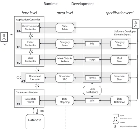
Fig. 1.Overview of the architecture (FMC notation).
2.2 Overview of the Architecture
Figure 1 shows the high level, compositional structure of our product line archi- tecture. As notation we use Fundamental Modeling Concepts (FMC) developed by Siegfried Wendt and described in [10] and [9].
The components needed at runtime are shown on the left, development on the right. The behavior of the system is described on thespecification level. These domain descriptions are transformed into the meta-level objects which control the components of thebase level at runtime.
The Application Controller starts the application and passes control to the User Command Controller. TheUser Command Controllerreacts to user commands invoked by the application menu according to the State Tablewhich describes the dynamic behavior of the application. When the user chooses a category and opens a legal event for processing, theEvent Controller reads from theCategory Ruleshow to handle this legal event.
TheEvent Controllerpasses control to theMask Controllerwhen the user opens a mask to enter data. The Mask Controller dynamically generates presentation objects from the Mask Objects Archives and shows them on the screen. It uses data references to establish connection between the input fields and the Event Data Object. (The same mechanism is used for dialogs but neither shown in the figure nor discussed in this paper.)
When the user issues the command to print documents, theApplication Con- trollerpasses control to the Document Formatter.
TheMask Controllerand theDocument Formatterneed the data of the current legal event. Whenever data access is necessary, they demand this service from theData Access Module, or, more specifically, theEvent Data Object.
During development, domain experts specify Mask Descriptions and Docu- ment Descriptions in domain-specific languages. The compilersmagicandformic translate these descriptions into Mask Objects Archives and Document Three- Address Codes, respectively.
The rules which tell theEvent Controllerwhat to do are specified inCategory Descriptions. The preprocessorinic translates them intoCategory Rules.
Software developers specify theData Definitionof the database. The compiler cdic translates it into a Data Dictionary and a Data Mapping. Using the Data Dictionary,magic,formic, and inicverify the data references in the descriptions.
The Data Mapping, read by the Event Data Object, provides information on tables, primary keys, and integrity constraints.
2.3 Remarks
The meta-level architectural pattern is discussed in, e.g., [11] and [18]. These descriptions focus on meta object-models which determine the creation and be- havior of base-level objects at runtime by a reflection mechanism.
In our architecture we use four mechanisms to provide and use metadata:
– description of data based on a specific type of relational data model – declarative and procedural domain-specific languages
– meta objects and rules given by logical expressions
– description of user command control by a specific type of statechart Both the domain knowledge and its transformation into workflows should not be hard-wired into the code. We tried to find the most convenient way.
The domain experts describe all layers of the application on the specification level – the data, the input and output, and the control – and these descriptions are transformed to control the base level. This solution is generic by means of mask and document generators. Their application, however, is very specific to the domain.
Interactive systems are often described by a layer architecture. Basically three conceptual layers are distinguished: the presentation, the domain logic, and the persistence layer, e.g., in [3].
Our architecture has layers in two dimensions, namely levels and respon- sibilities: in both the base level and the meta level we separate presentation,
domain logic, and persistence. The most interesting aspects of the meta-level architecture with respect to layering are:
– The layers in the meta level are tightly coupled, supporting the required domain-specific dependencies. The construction of the meta level follows the way domain experts describe the processing of legal events. For this reason we avoid indirection wherever possible.
– The layers in the base level are extremely decoupled. Engines in each base- level layer interpret the meta-level descriptions at runtime. These engines do not hard-wire domain-specific logic but process the meta-level descriptions.
The architecture provides access points to the layers; the engines do not depend on each other in any other way. Consequently the base-level engines can operate in different combinations in the various products of the product line.
3 Mechanism #1: Data Reference and Access by Symbolic Names
References to data items are needed in the meta level to specify data input, document contents, and workflow. We want to reference and access data items by names. We want to ignore where data is stored, and how:
3.1 Solution
Within an event, a symbolic name uniquely identifies a data item. The symbolic name determines the access path to the data in the database. At runtime, a dynamic data object serves as a container for this data and is responsible for its persistence.
Data model In order to define a
hbrt
vid enr date ...
1234 317 03.03.2003 Legal event marriage (root entity)
hbvp
vid ptype name anzve ...
1234 e Schneider 0
1234 s Bergmann 1
Data of fiancée and fiancé
hbve
vid ptype venr partner ...
1234 s 1 Olthoff
Data of previous marriages
references
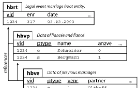
Fig. 2. A part of the data model illus- trating the principle of relationships.
naming convention for data items we need a convenient data model. In our application each legal event is assigned a unique root entity whose primary key is calledEvent Identifier(vid). We can then organize the event data in entities so that each entity has a 1:1 relationship or a cascading 1:n rela- tionship to the root entity. Each en- tity type has acompound primary key whose first item references the vid.
Figure 2 shows the principle in an example: Root tablehbrtcontains one row for the marriage identified by vid 1234. In tablehbvp there is one row for fiancé Schneider and one row for fiancée Bergmann, distinguished byptypeeand
s, respectively.anzveholds the number of previous marriages. Mrs. Bergmann, now divorced, was previously married to Mr. Olthoff, while Mr. Schneider is unmarried. So tablehbvehas one entry. This row is linked tohbrtby thevidand tohbvpby thevidand ptypes.3
Data reference Asymbolic nameconsists of therow identifier,i.e., the name of the entity type and the key information, and thefield identifier,i.e., the name of the attribute. A dot separates row identifier and field identifier. Using the example of figure 2, the symbolic name
hbve[s][1].partner
references Olthoff, name of the previous spouse of Mrs. Bergmann. It corre- sponds conceptually to the SQL statement
select partner from hbve where vid=? and ptype=’s’ and venr=1 Data access The data of one legal event is encapsulated in an Event Data Object (edo). Assisted by the Data Mapping,edo translates the symbolic name into a data access path. To continue with our example, edo reads in the Data Mapping that the compound primary key of hbveis composed of the attributes vid, ptype, and venr. The vid is the identifying attribute of theedo. So edohas all necessary key information to access the data of hbve[s][1].partner.
Theedoholds the data of an event in memory. It offers two strategies:
– Load all data rows identified by the samevid. This gives a full in-memory copy of the data belonging to this legal event.
– Load only those data rows requested by the application (lazy load). At each requestedochecks if the requested data is already in memory, i.e., contained in the currentedo.
Which strategy we choose depends on the infrastructure. It is even possible to mix both strategies, i.e., load the core data on creation of the edo, and load remaining data as requested by the application.
Concurrency control The data values in theEvent Data Object i.e., in mem- ory, have to be synchronized to the database. TheEvent Data Objectintercepts all database access and keeps a log of the state of the data in memory. Therefore, theEvent Data Objecthas to perform long duration transactions [16].
As databases do not support long transactions, theData Access Moduleuses a check-out/check-in mechanism. On creation of anedothe current user is recorded in the corresponding root entity, and access of other users is denied.4
3.2 Implementation
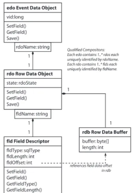
Figure 3 shows the implementation ofedo: The classEvent Data Object(edo) is a container of Row Data Objects (rdos). Each object of class edo is uniquely identified by thevidgiven on construction of theedo.edo’s methods to retrieve and store the values in the database delegate this responsibility to therdos,edo’s components.
3 Please don’t be troubled by cryptic abbreviations such ashbvp. They are reasonable abbreviations for Germans. Our domain experts love them.
4 This is in no way a restriction. It meets the working procedure in the offices.
Each object of classRow Data Object stores one row of data. It has an at- tributerdoNamewhose value is the row identifier. AnrdoNameis unique within therdos contained in one edo.
Each rdo consists of a Row Data
edo Event Data Object vid:long
SetField() GetField() Save()
rdoName: string
fldName: string state: rdoState SetField() GetField() Save()
rdo Row Data Object
fldType: sqlType fldLength: int fldOffset: int SetField() GetField() GetFieldType() GetFieldLength() fld Field Descriptor
rdb Row Data Buffer buffer: byte[]
length: int 1
1
1 1
1
1
references field data offset in rdb Qualified Compositons:
Each edo contains 1..* rdos each uniquely identified by rdoName.
Each rdo contains 1..* flds each uniquely identified by fldName.
Fig. 3.Code structure of theEvent Data Object(UML notation).
Buffer and a list of Field Descriptors.
TheRow Data Bufferstores the data.
It is allocated dynamically at runtime.
It is structured by the Field Descrip- tors. EachField Descriptorcontains the meta information of the correspond- ing database field: name, type, and length. This meta information is re- trieved from the system catalog of the database at runtime. The Field De- scriptor is used to make all necessary type conversions and to inform the application about the type of a data item in the database.
The rdo keeps track of its state with respect to the database in its at- tribute rdoState. The state of anrdo is characterized by the statechart in figure 4.
When created, the rdo is initial-
PERSISTENT TRANSIENT
UPDATE INSERT
Save
GetField GetField
create [found in database]
create [not found in database]
SetField
Save Save
GetField SetField
GetField SetField SetField
Fig. 4. Data Persistency and Synchro- nization (UML statechart notation).
ized from the database. If the corre- sponding row exists in the database, the data are loaded and the state of the object isPERSISTENT. Otherwise, it isTRANSIENT.
The methods of the rdo manipu- late the data in the Row Data Buffer and change the state of the rdo ac- cordingly. The methods SetField() and Save() change the state of the rdoto ensure the correspondence to the state of the data in the database.
The method Save() chooses the ap- propriate action on the database ac-
cording to the state of the rdo. In state UPDATESave() performs an update of the data row. In stateINSERTit inserts a new row in the table. The primary key of the new row is given by the rdoName. In statePERSISTENT or TRANSIENT, nothing needs to be done.
3.3 Discussion
Data model and data reference are simple: The data model consists of 1:1 and 1:n relationships only. It is mapped directly to the data definition of relational databases. Software developers and domain experts can easily keep both the data model and data reference in mind.
Data reference isdatabase system independent andprogramming language in- dependent:The symbolic name is a character string. It introduces an indirection between the data reference and data access. Data reference assigns a meaning to a database field – it establishes the necessary coupling in the meta level. The symbolic name may be translated to any database access technique.
Changes in the data definition affect the users of the data (Mask Descrip- tions andDocument Descriptions), while the data access mechanism remains un- changed.
Data access isgeneric and dynamic: edoprovides a data access mechanism and a data container. But edodoes not know which data to access. This infor- mation is contained only in the meta level: the symbolic names. edo resolves symbolic names at runtime.
Data access isportable:We had few problems with incompatibilities of SQL- databases, because we only use a small subset of SQL. We were even able to implement this SQL subset on a navigating database. A simple data model has led to database system independence.
The basic idea of theEvent Data Objectcan easily be extended to a check- out/check-in mechanism with a more sophisticated data mapping and naming convention. An option is to use an XML data model and a subset of XPath as naming convention to identify individual data items or even groups of them.
3.4 Related Mechanisms
Mechanism #1 is the basis for the other three mechanisms. They use the symbolic names.
3.5 Remarks
The concept of theEvent Data Objectand the use of a statechart to control the state of therdos was inspired by [12, Chap. 20].
The patterns in [3, Chap. 11 and 13] are closely related to our approach:
the Unit of Work, Metadata Mapping, and Repository patterns share concepts with the Event Data Object. However, we use the Event Data Object to store and retrieve data values whose access paths are givendynamically– by symbolic names, in fact. So theEvent Data Objectis more restricted in terms of the data model, but within that more generic.
The disconnected data set of ADO.NET (see e.g. [17]) has many similarities to theEvent Data Object. We already mentioned that an XPath-based naming convention could be used instead of ours.
4 Mechanism #2: Input and Output Control by Domain-Specific Descriptions
The data necessary to process a legal event is collected in a series of masks. The Mask Controller reacts on input immediately and guides the user through the event depending on the specific situation.
The data is then used to print all required documents. Usually, one event results in 5 – 20 documents, each comprising 1 – 4 pages.
4.1 Solution
For each event, platform-independent mask and document descriptions define which data is entered and how forms are filled out. They are writ- ten in domain-specific languages. At runtime, the compiled descriptions control the layout and behavior of masks and the content and formatting of documents.
Mask and document descriptions are written in languages which we designed according to the needs of the domain. Certainfunctionsof the languages provide the domain-specific features, notably
– properties of fields on masks and documents – processing of input
– formatting of output
We continue describing solution and implementation for masks and docu- ments separately.
4.2 Masks
Concept AMask Descriptiondefines static structure and dynamic behavior:
– The layout of the mask is defined by placing labels and input fields according to a column raster5
– Each input field is assigned the symbolic name of the data item which stores the input
– Input is assisted in certain fields by domain-specific functions, such as date functions, auto-completion, and calculations
– Actions are triggered by user interaction events (enter or quit the mask, enter or quit a field, enter a certain character in a field). Actions are domain- specific and may depend on parameters, data in input fields, or data of the current event
• (pre-)fill fields with data
• disable/enable fields
• check logical state of input
5 A template defining the layout of the masks was developed by a UI designer.
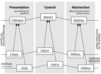
Fig. 5. The PAC architecture of the Mask Controller, exemplified with MFC (UML notation).
Implementation The compilermagictranslates the platform-independentMask Descriptions into the platform-dependent Mask Objects Archives. E.g., for MS Windows these are serialized C++ objects. At runtime, theMask Controlleruses theMask Objects Archives to control the mask.
TheMask Controllershown in figure 5 is designed according to the Presenta- tion Abstraction Control (PAC) architecture ([11]). The Presentation manages the screen, intercepts arriving messages, and routes these to the Control. The Abstraction maintains the data via the Event Data Object. Moreover, the Ab- straction keeps all meta-level information to provide the intelligence needed to handle user interactions which require executing functions, disabling fields, and so on. The Control – the mediator between Presentation and Abstraction – rec- ognizes the input, asks the Abstraction what to do, executes the appropriate functions, passes the result back to the Presentation, and returns control to the operating system. This behavior is not hard-wired into the code but determined by the meta-level information contained in the Abstraction.
4.3 Documents
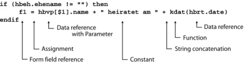
Concept ADocument Descriptiondefines layout and content:
– A set of fields defines the layout of the document. Each field is defined by a composition of rectangles, namely their positions on the document, length, and height.
– A set of formatting rules defines the properties of each field. A field may have several of about 20 properties, notably
if (hbeh.ehename != "") then
f1 = hbvp[$1].name + " heiratet am " + kdat(hbrt.date) endif
Data reference Function
String concatenation Constant
with Parameter
Form field reference Assignment
Data reference
Fig. 6.An exampleDocument Description.
• generic properties, e.g., flush left/right
• domain-specific properties, e.g., the number of in-between lines – Assignments define the content of each field.
• A field may contain static text or data items or any composition of these.
• The filling of fields may depend on parameters or on any data of the current event. The language provides if-then-else and switch-case for that.
For all this the language provides about 60 functions, implemented in the host language. Figure 6 gives an idea of the language.
Implementation The compilerformic translates a Document Description into platform-independentDocument Three-Address Code(see figure 1). One instruc- tion consists of a destination, two operands, and an operator.
At runtime, the Document Format-
Virtual Machine
Event Data Object
Database
Symbol Table
Three-Address Code Document
3AC
Function Pool Formatted
Document
R
Document Formatter
R
Fig. 7.Compositional structure of the Document Formatter.
tercomposes a document from theDoc- ument Three-Address Codeand the data provided by theEvent Data Object(fig- ure 7). First the Document Formatter loads the Three-Address Code and the Symbol Table into memory. With the help of theedoit replaces all data refer- ences in theSymbol Tablewith the cur- rent data values. Then the Virtual Ma- chineprocesses theThree-Address Code.
Using theFunction Poolit computes the content of each field and stores it in its destination in theSymbol Table. Af- ter that, the Symbol Table contains all information necessary to produce the document, i.e., field contents and prop- erties. Finally the Document Formatter traverses the Symbol Table and produces a virtual document in memory. The result is a completely processed, printable document.
4.4 Discussion
In eachMask Descriptionand in eachDocument Description highly valuable do- main expertise is captured and is readable, maintainable, and available for de- velopers. Each description serves as specification, code, and documentation. It is also guaranteed to be up-to-date, because this domain knowledge is captured in no other place.
Mask Descriptions and Document Descriptions inherently expose a high de- gree of correctness, because the languages guarantee consistency and prevent programming errors. Testing is reduced to a black-box test of functionality.
Configuration management of masks and documents works ideally because each item is contained in one file, and the files have ASCII format.
“Coding” of masks and documents comes close to specifying because the languages are declarative. They are procedural only where necessary.
4.5 Related Mechanisms
Mechanism #1 Masks and documents rely on data reference and access pro- vided by theEvent Data Object(edo). Masks and documents only work properly if the data references they use correspond to database fields.
Masks and documents can be parameterized. For example, the same Mask Descriptioncan collect similar data for different people if a key attribute, such as ptype, is parameter. Likewise, the sameDocument Descriptionis used for different people or different recipients.
Mechanism #3 Depending on the specific situation, theEvent Controllerde- termines which masks to present for input and which documents to offer as output.
Mechanism #4 TheMask Controlleris part of a Chain of Responsibility ([4]):
Messages resulting from user interaction are routed to the Control component of theMask Controller. If the required reaction involves only the current input field, it is handled by the Field Controler (FldCtrl); if several fields are involved the Mask Controler (MskCtrl) is responsible; if another mask is involved theEvent Controllercomes into play. Finally theUser Command Controlleris the top level of this chain.
4.6 Remarks
We use the Presentation Abstraction Control architectural pattern [11] for the design of the user interface. The dependencies on the platform are encapsu- lated in the Presentation component. Abstraction and Control are platform- independent.
The concepts used for the design of the Document Three-Address Code and the implementation of formiccome from [1] and [6].
Both compilers,magic and formic, are made with lex&yacc. Subroutines in formic are implemented with the m4 macro processor.
5 Mechanism #3: Application and Domain Logic by a Rule Engine
The handling of a legal event is organized as a workflow: it leads the user through a series of masks. It results – after a juridical check – in printing several docu- ments. The order of the masks and the selection of the documents depends on the specific situation, i.e., on personal data.
While the structure of the workflow is common to all categories of legal events, the concrete series of masks and documents within a category is do- main knowledge. As such, it would be inappropriate to program the workflow in technical code. Instead, we continue to keep the domain knowledge in the meta level.
5.1 Solution
The workflow is controlled by properties. The properties describe the se- ries of masks and documents and the conditions on which masks should be presented and documents should be printed. These domain-specific prop- erties are described in the meta level. At runtime, a rule engine controls the workflow using these descriptions.
Each mask or document has the following properties: A name, parameters which are substituted on invocation, and conditions which restrict its use de- pending on the current data of a legal event.
The complete workflow of a category of legal events consists of a list of all possible masks and documents and the conditions.6
The conditions – logical expressions – are the heart of the application and domain logic. All constraints are grouped in classes of conditions. Each class comprises all permissible states of interdependent data items. This is called a logical classand thelogical statewithin a class. Each condition can be referenced by its logical class and logical state. To give an example: In processing a marriage, the logical class “marital status” permits the logical states “single” or “divorced, number of previous marriages > 0”, whereas ”married” is not allowed. The logical expressions for the fiancée are
hbvp[s].famstand=="ledig" && hbvp[s].anzve==0 hbvp[s].famstand=="geschieden" && hbvp[s].anzve>07
6 Some masks or documents are repeated several times. The number of repetitions depends on the current data, e.g., the number of children. Our descriptions allow to specify repetition, but we omit the details in this paper.
7 famstand = marital status, ledig = single, anzve = number of previous marriages, geschieden = divorced
5.2 Implementation
A Category Description contains the properties of a category, i.e., the series of masks and documents and the conditions.Category Descriptions are files in ASCII format, structured bysections andtags.8
The preprocessorinictranslates aCategory Descriptioninto aCategory Rules file. First, inic checks the syntax of data references against the Data Dictionary (see figure 1) to guarantee the correctness of all data references. Theninictrans- forms the conditions into Reverse-Polish Notation. This simplifies and speeds up evaluation of the expressions at runtime.
At runtime, the Event Controller starts the processing of a legal event by transforming the Category Rules into runtime objects. During input, the rule engine evaluates the conditions to control the behavior of the workflow.
5.3 Discussion
Using the concept of logical classes and states we initially intended to reach a more declarative way of describing the domain logic than we finally did. Inter- national civil law brings up a complexity which is hard to capture in a com- prehensive set of logical expressions. Domain experts often prefer to design the processing of the legal event in terms of controlling the input on the masks.
Many regulations of the domain are formulated in this manner ([14]).
5.4 Related Mechanisms
Mechanism #1 Category Descriptions reference data items by their symbolic name. The rule engine uses theedoto resolve these references and to access the values of the data items.
Mechanism #2 The Event Controller uses the rule engine to determine the series of masks and documents and gives control to theMask Controllerand the Document Formatter. In particular, it provides the parameters and the reference to theedofor the processing of masks and documents.
The Mask Descriptions refer to the Category Rules, which describe the in- tegrity conditions of input values. At runtime theMask Controllerevaluates the conditions by means of the rule engine.
6 Mechanism #4: User Command Control by a Finite State Machine
So far we have described how data is entered on masks and is used to print documents. The controlling of the application is still missing. For example, before users can work at a legal event, they choose the category from the menu and open either an existing event or set up a new one. After entering the data, they issue a printing command.
8 The style of Windows ini-files. Our product line started long before XML was in- vented.
6.1 Solution
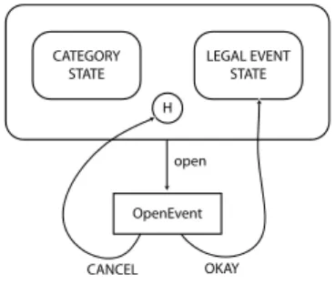
Describe top level user commands as events which trigger actions and move the application from one state to another. At runtime, a finite state machine reacts to the events by executing the actions and transitions.9 Our statechart consists of sets of states, events, actions, return codes, and two types of transitions. It is a variant of the statecharts introduced by Harel in [5].
In astateaneventmay occur. State
H CATEGORY
STATE
LEGAL EVENT STATE
OpenEvent open
CANCEL OKAY
Fig. 8.Part of the user command con- trol statechart.
plus event define the action to be exe- cuted. Each action issues areturn code.
Action plus return code define the fol- low-up state. Figure 8 gives an exam- ple. Both in CATEGORY STATE and in LEGAL EVENT STATEthe user mayopen a legal event for processing. If the user confirms the Open Event dialog with OKAY he will arrive in LEGAL EVENT STATE. Otherwise he will return to the state where he came from, indicated by anH.
6.2 Implementation
The triggering of a menu command is routed to the User Command Controller whose finite state machine runs the statechart. The statechart is defined by a state table, a static data structure which contains the flattened statechart.
At runtime, the User Command Controller uses this state table to control the behavior of the application. Events come from user interactions. Actions are methods of theApplication Controller.
6.3 Discussion
Ergonomics Modeling the control flow of a program with a statechart supports software ergonomy. The statechart maps the working procedure in the office to the control flow of the program. The result is a clear, transparent behavior of the program which users understand effortlessly. Our users have never asked questions such as “where am I?” or “how did I get here?”.
It was possible to keep the statechart simple because all categories and events are processed according to the same pattern (see mechanisms #2 and #3). All of them are handled with the same actions.
Static data structure We decided to implement the state table in a static data structure instead of a dynamic one, because statecharts rarely change in our products.
9 Please do not confuse the events in the statechart with legal events.
Product Line The description of the statechart in the meta level decouples application control from GUI infrastructure. E.g., on the MS Windows platform we redirect MFC’s message map to theUser Command Controller’s state table.
The implementation of the finite state machine is reusable with other state- charts. E.g., the functionality of the software can be reduced by removing states and transitions from the statechart. Variant products can sometimes be obtained by providing a different state table.
6.4 Related Mechanisms
TheUser Command Controlleris not directly connected to mechanisms #1, #2, or #3. The repositoryedofacilitates the use of the finite state machine: actions share data in the repository.
6.5 Remarks
There are several techniques to implement statecharts, see [13] and [7].
As shown in figure 8 our statechart is a bipartite graph where states are dis- tinguished from actions. This notation visualizes behavior clearly and coherently.
We used it long before UML came up. Nevertheless, this notation can easily be made UML conformant by using stereotypes to distinguish states from actions.
7 Conclusion
To conclude this paper, we discuss the contribution of the four mechanisms – #1: Data Reference and Access by Symbolic Names
– #2: Input and Output Control by Domain Specific Descriptions – #3: Application and Domain Logic by a Rule Engine
– #4: User Command Control by a Finite State Machine to the realization of variability in the product line.
7.1 Realizing Variability of the Domain
Mechanism #1 TheEvent Data Object is a core asset used in all products.
Each product gets a Data Definitionof its own.
Mechanism #2 The domain-specific languages are core assets used for all products. They need extension for some products (e.g., Austrian registry offices need extra formatting which is not used in Germany).
Mask ControllerandDocument Formatter are core assets. They need adapta- tion if a certain function needs different implementations for a product.
Mask Descriptions andDocument Descriptions are product-specific. Some de- scriptions can be used for more than one product.
Mechanism #3 Event Controllerandinic are core assets used in all products, whileCategory Descriptions are product-specific.
Mechanism #4 TheUser Command Controlleris a core asset used in all prod- ucts, while theState Tableis product-specific.
7.2 Realizing Variability of Technology
Mechanism #1 Different database technologies require different implementa- tions of some parts of theEvent Data Object and theData Access Module, while data reference remains unchanged.
Mechanism #2 Changes due to technology do not affect Mask Descriptions andDocument Descriptions at all.
Printing depends on printing technology, but theDocument Formatter does not. (We do not go into the details here.)
TheMask Controller depends on GUI infrastructure to a high degree, so do theMask Objects Archives andmagic, which has to generate output appropriately.
The mask description language depends to a certain degree on the possibilities which the platform provides. We kept both magic and the mask description language downward compatible.
Mechanism #3 is completely independent of technology.
Mechanism #4 TheUser Command Controller depends on the GUI. Events resulting from user interactions have to be redirected to the User Command Controller.
7.3 Applicability of these Mechanisms Our mechanisms will suit if
– events have to be processed and follow certain patterns – data can be modeled according to our principles – many different masks and forms are needed – several products are developed
– domain logic should be saved when technology changes and vice versa 7.4 Issues
If domain-specific languages are used to capture domain logic, the scope of these languages will define the capabilities of the products. This is both an advantage and a disadvantage.
The system has the advantage of beinguniform. Both developers and users understand it easily. It’s in the nature of this architecture that features of the same type behave in the same way. They appear in the meta level many times but their processing is implemented only once.
The disadvantage is that special cases, exceptions, or ad-hoc variations are impossible or only possible with more effort.
Developing this architecture and these mechanisms required not only a deep and thorough understanding of the domain but also the discovery ofpatterns in thedomain. The mechanisms used in this architecture fit to these patterns. In particular, our data model matches the structure of the legal events. We took it as a basis to schematize the domain. “Problem analysis takes you from the level of identifying the problem to the level of making the descriptions needed to solve it” says Michael Jackson in [8].
We join domain expertise with software engineering. Domain experts directly contribute to software development: In the data references they have found a powerful, efficient means of expression. As the owners of Mask Descriptions,Doc- ument Descriptions, andCategory Descriptions they have gained control over the domain-specific aspects of application development.
The analysis of the domain has led to languages which allow the description and specification of product behavior. Variant descriptions specify variants in the product line.
References
1. A. V. Aho, R. Sethi, and J. D. Ullman: Compilers: Principles, Techniques, and Tools, Addison-Wesley 1986
2. P. Clements, L. Northrop:Software Product Lines, Addison-Wesley 2002
3. M. Fowler:Patterns of Enterprise Application Architecture, Addison-Wesley 2003 4. E. Gamma, R. Helm, R. Johnson, J. Vlissides:Design Patterns, Addison-Wesley
1995
5. D. Harel:Statecharts: a Visual Formalism for Complex SystemsinScience of Com- puter Programming No. 8, p. 231 – 274
6. A. I. Holub:Compiler Design in C, Prentice-Hall 1990
7. I. Horrocks:Constructing the User Interface with Statecharts, Addison-Wesley 1999 8. M. Jackson: Problem Frames – Analyzing and structuring software development
problems Addison-Wesley 2001
9. F. Keller et al.:Improving Knowledge Transfer at the Architectural Level: Concepts and Notations in Proceedings of the 2002 International Conference on Software Engineering Research and PracticeLas Vegas 2002
10. A. Knöpfel:FMC Quick Introduction, Hasso Plattner Institute for Software Sys- tems Engineering, Potsdam, Germany, 2003 <http://fmc.hpi.uni-potsdam.de>
11. F. Buschmann, R. Meunier, H. Rohnert, P. Sommerlad, M. Stal:Pattern-Oriented Software Architecture, John Wiley & Sons 1996
12. J. Rumbaugh, M. Blaha, W. Premerlani, F. Eddy, W. Lorensen: Object-oriented Modeling and Design, Prentice-Hall 1991
13. M. Samek:Practical Statecharts in C/C++, CMP Books 2002
14. H. Schmitz, H. Bornhofen (editors): Dienstanweisung für die deutschen Standes- beamten und ihre Aufsichtsbehörden2. Auflage, Verlag für Standesamtswesen 2001 15. H. Schmitz, H. Bornhofen (editors):Personenstandsgesetz 10. Auflage, Verlag für
Standesamtswesen 2003
16. A. Silberschatz, H. F. Korth, S. Sudarshan:Database System Concepts4th edition, McGraw-Hill 2002
17. T. Thai, H. Q. Lam:.NET Framework Essentials: Introducing the .NET Frame- work, O’Reilly 2001
18. J. W. Yoder, R. Johnson:The Adaptive Object-Model Architectural Style inPro- ceedings of the Working IEEE/IFIP Conference on Software Architecture 2002
<http://www.joeyoder.com/papers/>