Debugging Quadrocopter Trajectories in Mixed Reality
Burkhard Hoppenstedt1, Thomas Witte2, Jona Ruof2, Klaus Kammerer1, Matthias Tichy2, Manfred Reichert1, and R¨udiger Pryss1
1 Institute of Databases and Information Systems, Ulm University, Ulm, Germany
2 Institute of Software Engineering and Programming Languages, Ulm University, Ulm, Germany
burkhard.hoppenstedt@uni-ulm.de
Abstract. Debugging and monitoring robotic applications is a very in- tricate and error-prone task. To this end, we propose a mixed-reality approach to facilitate this process along a concrete scenario. We con- nected the Microsoft HoloLens smart glass to the Robot Operating Sys- tem (ROS), which is used to control robots, and visualize arbitrary flight data of a quadrocopter. Hereby, we display holograms correctly in the real world based on a conversion of the internal tracking coordinates into coordinates provided by a motion capturing system. Moreover, we describe the synchronization process of the internal tracking with the motion capturing. Altogether, the combination of the HoloLens and the external tracking system shows promising preliminary results. Moreover, our approach can be extended to directly manipulate source code through its mixed-reality visualization and offers new interaction methods to de- bug and develop robotic applications.
Keywords: Quadrocopter·Mixed Reality·Robot Operating System· 3D Trajectories
1 Introduction
In recent years, quadrocopters became affordable for a wider audience and were successfully used for commercial use cases, such as delivery ([7], [22]). The au- tonomous operation of quadrocopters requires complex approaches, such as plan- ning offlight paths [13],coordinated actions [20], or collision avoidance [10]. A similar development took place in the field of augmented reality. Especially smart glasses provide more features and offer a better interaction with the real world.
The development efforts for quadrocopter software are very high and we see po- tential in utilizing augmented reality to assist the development of quadrocopter software. Augmented reality has proven to be a suitable approach for complex tasks, such as machine control [19]. In this work, we connected a quadrocopter via the Robot Operating System (ROS) to a Microsoft HoloLens. In the smart glass, we can see all the trajectories of the flight plan. Using the proposed frame- work, it is possible to receive an instant 3D feedback for the programming of a planned path and the method can be seen asvisual 3D programming [12].
The remainder of this paper is structured as follows: Section 2 discusses re- lated work, while Section 3 introduces the background for quadrocopters, Mixed Reality, and the Robot Operating System. In Section 4, the developed prototype is presented, in which the mixed-reality application and the processing pipeline are presented. Threats to validity are presented in Section 5, whereas Section 6 concludes the paper with a summary and an outlook.
2 Related Work
Quadrocopters have been already tested in the context of Mixed Reality [14].
Hereby, the simplification of debugging, the elimination of safety risks, and the easier development of swarm behavior by complementing physically existing robots with simulated ones were named as outstanding advantages. Further- more, a study for the programming of a small two-wheeled robot [16] revealed no impact on the learning performance when using Augmented Reality (AR).
The debugging of quadrocopters with a fixed camera in combination with LEDs is presented by [11]. In this approach, autonomously driving robots are operated in a testing environment, and a camera stream is overlapped with AR data. Fi- nally, the use of mobile LED projectors for easily understandable visualizations of robot data is presented by [15]. However, the projection is limited to 2D data and might be insufficent for complex flight paths of quadrocopters. However, to the best of our knowledge, a combination of technologies as shown in this work, has not been presented in other works so far.
3 Fundamentals
3.1 Robot Operating System
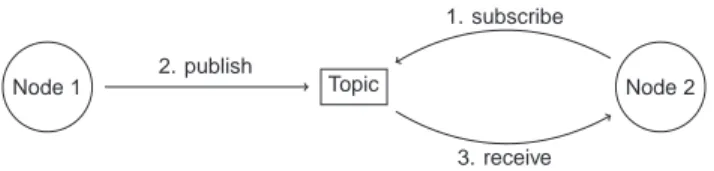
The Robot Operating System (ROS) [18] is ameta operating systemdesigned for the development of robot-specific applications. It is not classified as a standard operating system, it is rather a collection of programs. ROS is basically designed as a peer-to-peer architecture and supports the publish and subscribe pattern (see Fig. 1). A central instance, denoted as master, provides a central lookup directory and organizes the connections between different programs. The clients of ROS are callednodes, and communicate by publishing messages in a YAML- like [8] syntax. All messages are send to so-calledtopics, which can be seen as a black board for messages. This concept allows the asynchronous transfer of large amounts of data.
3.2 Mixed Reality
We used the Microsoft HoloLens to utilize mixed-reality concepts. Mixed reality, in turn, is a concept in which the real environment and the virtual environment are combined. Concerning theVirtuality Continuum[17], mixed reality has the higher intersection of reality and virtuality. More specifically, the HoloLens uses
Node 1 Topic Node 2 1. subscribe
2. publish
3. receive
Fig. 1.Publish and Subscribe Principle of the Robot Operating System
spatial mapping to create a virtual model of the real environment. Therefore, in- teractions of holograms and real-world objects become possible. Mixed Reality is widely used in the contexts of industrial maintenance, medicine, and architec- ture. The HoloLens is equipped with various sensors, such as a depth sensor, a RGB Camera, and an ambient light sensor. Infinite projections are not possible, neither to the distance nor to the proximity. With a weight of 579g, the HoloLens may cause dizziness when used for a longer period of time. In an intensive use, the battery lasts for about 2.5 hours, which inhibits a long-time usage.
3.3 Tracking
In our architecture, the HoloLens is tracked with a motion capturing system, which uses an array of infrared emitting and receiving cameras. The HoloLens is equipped with a set of three (at least) reflective markers (see Fig. 2, right side).
The markers are placed asymmetrically, since a symmetric marker placement would yield an ambiguous tracking position. Furthermore, the HoloLens provides its own tracking, which is relative to the starting pose. The motion capturing system, in turn, provides an accuracy on millimeter level and is not susceptible to drifts due to dead reckoning, which outperforms the internal HoloLens tracking (see Fig. 2, left). After a calibration, the pose data is sent to the ROS as avirtual reality peripheral network stream [23].
4 System Overview
Using a motion capturing system with 16 cameras, the system can detect, iden- tify, and track objects with high precision. The motion capturing software then makes this information available to the ROS through a continuous stream of pose data. Inside the ROS network, the decentral and dynamic nature of ROS makes it possible to connect components and other applications, such as the control of a quadcopter swarm, in a flexible way. The motion data can, for example, be processed to estimate the velocity and acceleration of objects, which is of paramount importance for the motion planning and control of quadrocopters.
This amount of different data sources and objects might be complex to grasp or understand, and is therefore often visualized using tools such as rviz [4]. We use the same data format as common rviz marker messages to feed our mixed-reality overlay. This enables to use the HoloLens as a plug and play replacement for rviz
-2 -1.5 -1 -0.5 0 0.5 1 1.5 2 -1
-0.5 0 0.5 1 1.5 2
position.x [m]
position.y [m]
hololens tracking optitrack tracking
reective marker ir camera
Fig. 2.Tracking Accuracy (left), Marker Reflection (right)
object detection
and tracking ROS rosbridge
x y
z
quadcopter
x y
z
hololens x
y z
world
x y
z
hololens_origin
Fig. 3. Architecture of the system (left). Coordinate systems and transformations (right).
and connect the 3D visualizations directly to the objects that provide the data.
The communication between the HoloLens and the ROS is realized through a rosbridge [5]. The latter translates the TCPROS [6] message passing protocol to a websocket-based protocol. The messages are then decoded using a HoloLens rosbrige [1], interpreted, and eventually displayed on the HoloLens.
The HoloLens uses its own motion tracking [2], including internal cameras and its Inertial Measurement Unit (IMU) to localize itself and keep the visual overlay stable with respect to the environment. The reference frame of this inter- nal tracking is not directly available to the ROS components of our system. We can only observe the tracked position of the HoloLens itself (in the static world frame of the motion capturing system) and communicate the internal (estimated) position back to the ROS network (see Figure 3). Using these two coordinate
transformations, we are able to calculate the position of arbitrary tracked objects with respect to the internal HoloLens reference framehololens origin.
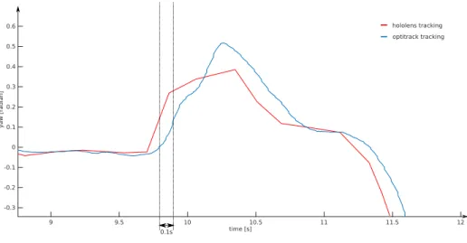
This setup is highly sensitive to timing. The transmission of data through different hosts over a network as well as inside the ROS network introduces a significant delay to the pose data that is used to transform the object positions into the mixed-reality overlay. An additional delay is related to the tracking of objects and the HoloLens itself. Figure 4 shows a time difference in the tracking data, received from the HoloLens and the motion capturing system in ROS of at least 0.1s. This results in a shifted or delayed positioning of the overlay, which is especially visible during fast head turns or fast movements. We currently do not estimate or compensate this delay as it would be necessary to synchronize clocks across multiple systems. Instead, we update the HoloLens origin frame only sporadically during periods of low head movements. This way, the internal tracking of the HoloLens can keep the overlay stable, and the positioning of the overlay is corrected when timing is less critical.
9 9.5 10 10.5 11 11.5 12
-0.3 -0.2 -0.1 0 0.1 0.2 0.3 0.4 0.5 0.6
yaw [radian]
time [s]
0.1s
hololens tracking optitrack tracking
Fig. 4.Time difference of the received pose data in ROS.
The system was tested in the quadrocopter lab at Ulm University. An area of approximately 9.5×5.5×4 meters is used as the room for the quadrocopters to operate and make maneuvers. TheOptitrack [3] tracking system is installed closely to the ceiling of the lab. The HoloLens has been made trackable with markers, so that the motion capturing system can deliver a continuos stream of pose information. This stream is sent to a computer in the lab, running an instance of ROS. Finally, a ROS visualization is sent back to the HoloLens. This message contains all the information about the current visualization. It further includes lists of all objects with their location and required changes (e.g., modify, delete, insert). The HoloLens parses this messages and transfers its content into
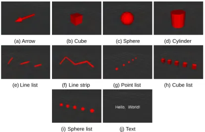
the internal object representation. The visualisation message can be seen as a toolbox to build arbitrary complex scenes from the provided basic components (see. Fig 5). A flight path can then be visualized using, e.g., a line strip or a list of points, while arrows can be used to visualize the desired acceleration and velocity vectors at a waypoint.
(a) Arrow (b) Cube (c) Sphere (d) Cylinder
(e) Line list (f) Line strip (g) Point list (h) Cube list
(i) Sphere list (j) Text
Fig. 5.Basic 3D Components
5 Threats to Validity
The following limitations of the presented approach need to be discussed. First, the approach has not been tested in a study yet. Thus, it is unclear if users benefit from the immersive representation of quadrocopter flight paths in terms of speed or usability. Second, the approach relies heavily on a robust network connection, therefore network problems will negatively influence the application behavior. In general, network limitations might reduce the performance of animations and the general application framerate. Third, the system is designed under laboratory conditions and cannot be applied outside unless a marker-based environment is established.
6 Summary and Outlook
We presented a prototype for visualizing data of a quadrocopter system (e.g., quadcopter trajectories) in Mixed Reality. The communication is realized using the Robot Operating System. Different 3D objects serve as a toolkit to build
visualizations in the context of quadrocopter flight plan programming. In a next step, we will extend the approach from the monitoring to the interaction level.
Using the concept of source origin tracing, as used, e.g., by [9], it is possible to directly manipulate constants in source code through the visualization. For example, when using a tap gesture, the position of an object in the room could be modified as well as the attached source code. Therefore, the user of the application may program his or her quadrocopter through immersive interactions with the displayed holograms. As the proposed approach contains novel user interaction patterns, it should be evaluated in a usability study (cf. [21]) to identify the mental load during its use. In this context, the speed advantage compared to a traditional approach should be evaluated. Altogether, this work has shown that the combination of the Robot Operating System and Mixed Reality is a promising strategy.
References
1. HoloLens-Rosbridge. https://github.com/roastedpork/hololens-rosbridge, accessed: 2019-02-13
2. HoloLens Tracking-System. https://docs.microsoft.com/en-us/windows/
mixed-reality/enthusiast-guide/tracking-system, accessed: 2019-02-13 3. Optitrack.http://optitrack.com, accessed: 2019-02-15
4. ROS Vizualization rviz.http://wiki.ros.org/rviz, accessed: 2019-02-13 5. ROSBridge.http://wiki.ros.org/rosbridge_suite, accessed: 2019-02-13 6. TCPROS.http://wiki.ros.org/ROS/TCPROS, accessed: 2019-02-15
7. Bamburry, D.: Drones: Designed for product delivery. Design Management Review 26(1), 40–48 (2015)
8. Ben-Kiki, O., Evans, C., Ingerson, B.: Yaml ain’t markup language (yaml) version 1.1. yaml. org, Tech. Rep p. 23 (2005)
9. Breckel, A., Tichy, M.: Live programming with code portals. In: Workshop on Live Programming Systems - LIVE’16 (2016)
10. Gageik, N., M¨uller, T., Montenegro, S.: Obstacle detection and collision avoid- ance using ultrasonic distance sensors for an autonomous quadrocopter. University of Wurzburg, Aerospace information Technologhy (germany) Wurzburg pp. 3–23 (2012)
11. Ghiringhelli, F., Guzzi, J., Di Caro, G.A., Caglioti, V., Gambardella, L.M., Giusti, A.: Interactive augmented reality for understanding and analyzing multi-robot sys- tems. In: Intelligent Robots and Systems (IROS 2014), 2014 IEEE/RSJ Interna- tional Conference on. pp. 1195–1201. IEEE (2014)
12. Green, T.R.G., Petre, M., et al.: Usability analysis of visual programming envi- ronments: A ’cognitive dimensions’ framework. Journal of visual languages and computing7(2), 131–174 (1996)
13. Hehn, M., DAndrea, R.: Quadrocopter trajectory generation and control. In: IFAC world congress. vol. 18, pp. 1485–1491 (2011)
14. Hoenig, W., Milanes, C., Scaria, L., Phan, T., Bolas, M., Ayanian, N.: Mixed reality for robotics. In: Intelligent Robots and Systems (IROS), 2015 IEEE/RSJ International Conference on. pp. 5382–5387. IEEE (2015)
15. Leutert, F., Herrmann, C., Schilling, K.: A spatial augmented reality system for in- tuitive display of robotic data. In: Proceedings of the 8th ACM/IEEE international conference on Human-robot interaction. pp. 179–180. IEEE Press (2013)
16. Magnenat, S., Ben-Ari, M., Klinger, S., Sumner, R.W.: Enhancing robot program- ming with visual feedback and augmented reality. In: Proceedings of the 2015 ACM Conference on Innovation and Technology in Computer Science Education.
pp. 153–158. ACM (2015)
17. Milgram, P., Takemura, H., Utsumi, A., Kishino, F.: Augmented reality: A class of displays on the reality-virtuality continuum. In: Telemanipulator and telepresence technologies. vol. 2351, pp. 282–293. International Society for Optics and Photonics (1995)
18. Quigley, M., Conley, K., Gerkey, B., Faust, J., Foote, T., Leibs, J., Wheeler, R., Ng, A.Y.: Ros: an open-source robot operating system. In: ICRA workshop on open source software. vol. 3, p. 5. Kobe, Japan (2009)
19. Ralston, S.E.: Augmented vision for survey work and machine control (Jul 25 2000), uS Patent 6,094,625
20. Ritz, R., M¨uller, M.W., Hehn, M., D’Andrea, R.: Cooperative quadrocopter ball throwing and catching. In: Intelligent Robots and Systems (IROS), 2012 IEEE/RSJ International Conference on. pp. 4972–4978. IEEE (2012)
21. Schobel, J., Pryss, R., Probst, T., Schlee, W., Schickler, M., Reichert, M.: Learn- ability of a configurator empowering end users to create mobile data collection instruments: Usability study. JMIR mHealth and uHealth6(6) (2018)
22. Stolaroff, J.: The need for a life cycle assessment of drone-based commercial package delivery. Tech. rep., Lawrence Livermore National Lab.(LLNL), Livermore, CA (United States) (2014)
23. Taylor II, R.M., Hudson, T.C., Seeger, A., Weber, H., Juliano, J., Helser, A.T.:
Vrpn: a device-independent, network-transparent vr peripheral system. In: Pro- ceedings of the ACM symposium on Virtual reality software and technology. pp.
55–61. ACM (2001)