Research Collection
Doctoral Thesis
Design and Fabrication of Thin Folded Members with Digital Concrete Processes
Author(s):
Szabo, Anna Publication Date:
2020-11
Permanent Link:
https://doi.org/10.3929/ethz-b-000453808
Rights / License:
In Copyright - Non-Commercial Use Permitted
This page was generated automatically upon download from the ETH Zurich Research Collection. For more information please consult the Terms of use.
ETH Library
DISS. ETH NO. 27199
DESIGN AND FABRICATION OF THIN FOLDED MEMBERS WITH DIGITAL CONCRETE PROCESSES
A thesis submitted to attain the degree of DOCTOR OF SCIENCES of ETH ZÜRICH
(Dr. sc. ETH Zürich)
presented by ANNA SZABÓ
M. Sc. in Architecture and Engineering, Budapest University of Technology and Economics
born on 27.03.1987 citizen of Hungary
accepted on the recommendation of Prof. Matthias Kohler
Prof. Fabio Gramazio Prof. Dr. Robert J. Flatt
Dr. Nicolas Roussel Prof. Dr. Rafael G. Pileggi
2020
Acknowledgements ... 6
Abstract ... 8
1 Introduction ... 10
1.1 General introduction ... 10
1.2 Historical overview of folded structures ... 12
1.3 Research objective ... 15
1.4 Structure of the thesis ... 16
2 State of the art ... 19
2.1 Contemporary folded concrete architecture ... 19
2.1.1 In-situ folded concrete construction ... 19
2.1.2 Prefabricated folded concrete construction ... 21
2.1.3 On-site prefabricated folded concrete construction ... 24
2.1.4 Conflict between design complexity and fabrication efficiency ... 25
2.2 Research in concrete construction processes ... 26
2.2.1 To use formwork or not to use formwork? ... 27
2.2.1.1 No formwork ... 27
2.2.1.2 Stay-in-place/lost formworks ... 30
Printed stay-in-place formworks infilled with concrete ... 30
Party or fully covered lost formworks ... 31
2.2.1.3 Non-traditional temporary formworks ... 33
Flexible moulds as temporary supports ... 33
Granular or fluid materials as temporary support ... 36
Thin or reduced formworks supported with active hydration control ... 38
2.3 Smart Dynamic Casting (SDC) ... 41
2.3.1 Material concept - set on demand concrete ... 41
2.3.2 SDC fabrication setup ... 42
2.3.3 Formworks for SDC ... 44
3 Adapting SDC to Thin Folded Geometries ... 47
3.1 Introduction ... 47
3.2 Materials and methods ... 49
3.2.1 SDC fabrication setup for thin folded geometries ... 50
3.2.1.1 Digital control for SDC to produce thin folded geometries ... 52
3.2.2 Initial robotic experiments ... 53
3.2.3 Second phase of robotic experiments ... 54
3.2.4 Penetrometer tests ... 55
3.2.4.1 Offline penetrometer tests ... 55
3.2.4.2 Online penetrometer tests ... 55
3.3 Results ... 56
3.3.1 Initial robotic experiments ... 56
3.3.2 Offline penetrometer tests ... 57
3.3.3 Online penetrometer tests ... 58
3.3.4 Second phase of robotic experiments ... 59
3.3.4.1 Robotic experiment as material evaluation ... 59
3.3.4.2 Robotic experiments to explore possible designs ... 60
3.4 Discussion ... 63
3.4.1 Slipforming process model ... 64
3.4.2 Adaptation of mix design and acceleration strategy ... 65
3.4.3 Modifications based on offline tests ... 66
3.4.4 Modifications based on online tests ... 67
3.4.5 Robotic experiments as shape exploration ... 68
3.5 Conclusion ... 70
4 Mastering Yield Stress Evolution and Formwork Friction for Smart Dynamic Casting ... 73
4.1 Introduction ... 73
4.2 Materials and Methods ... 74
4.2.1 Materials ... 74
4.2.1.1 Self-compacting concrete ... 75
4.2.1.2 UHPFRC ... 76
4.2.2 Methods ... 77
4.2.2.1 Slump tests ... 77
4.2.2.2 Penetration tests ... 78
4.2.2.3 Calorimetry ... 78
4.2.2.4 Friction tests ... 78
4.3 Part 1: Mastering the yield stress evolution ... 80
4.3.1 Results ... 80
4.3.1.1 Spread flow ... 80
4.3.1.2 Penetration tests ... 82
4.3.1.3 Calorimetry ... 84
4.3.2 Discussion ... 86
4.3.2.1 Initial yield stress after accelerator addition ... 86
4.3.2.2 Penetration resistance / Strength evolution ... 87
4.3.2.3 Cement hydration ... 88
4.4 Part 2: Friction tests ... 88
4.4.1 4.1 Results ... 88
4.5 Part 3: A theoretical model for the SDC process window ... 92
4.5.1 Reformulating the process window with the ‘SDC number’ ... 92
4.5.2 Practical considerations ... 96
4.6 Conclusions ... 100
4.7 Implications ... 101
5 Establishing Admixture Controlled Digital Casting (ACDC): a solution for fast building rates ... 104
5.1 Introduction ... 104
5.2 Materials and methods ... 105
5.2.1 Materials ... 105
5.2.2 Slump tests ... 107
5.2.3 Calorimetry ... 107
5.2.4 Slow penetration tests ... 107
5.2.5 Uniaxial compression tests ... 108
5.2.6 Robotic experiments with the ACDC process ... 108
5.2.6.1 Process development of ACDC with deformation tests and force sensor measurements ... 110
5.3 Results ... 112
5.3.1 Calorimetry ... 112
5.3.1.1 Offline tests ... 112
5.3.1.2 Online tests ... 113
5.3.2 Slow penetration tests ... 114
5.3.3 Robotic experiments ... 117
5.3.3.1 Deformation tests ... 117
5.3.3.2 Force sensor measurements ... 118
5.4 Discussion ... 119
5.4.1 Cement hydration ... 119
5.4.1.1 Hydration kinetics with custom aluminium sulfate type of acceleration .. 119
5.4.1.2 Consequences of the offline and online acceleration method on hydration 121 5.4.2 Slow penetration as a continuous measurement of yield stress ... 121
5.4.3 Buildability for SDC with the different mixes ... 122
5.4.4 Deformation tests ... 123
5.4.5 Buildability for ACDC ... 124
5.5 Conclusion ... 125
6 In-tense ACDC for producing thin folded structures ... 127
6.1 Introduction ... 127
6.2 Design of the folded structure demonstrator ... 127
6.3 Basic experimental conditions ... 128
6.3.1 ACDC fabrication setup for thin folded concrete structures ... 128
6.3.1.1 Material composition and process parameters ... 129
6.3.1.2 In-Tense formworks with folded geometries ... 129
6.3.1.3 Digital control and material monitoring ... 130
6.4 Folded prototypes as experimental results ... 131
6.4.1 General observations during the ACDC fabrication process ... 131
6.4.2 Ram Board ... 131
6.4.3 Heat-bonded geotextile ... 133
6.4.4 0.2mm PE foil ... 135
6.4.5 Stretchable woven textile ... 137
6.5 Assembly of the prototypes ... 139
6.6 Discussion ... 141
6.6.1 Processing ease for In-Tense ACDC ... 141
6.6.2 Surface quality and casting pattern ... 143
6.6.3 Folded geometries with In-Tense ACDC ... 147
6.7 Conclusions ... 148
7 Application of ACDC to self-supporting thin formworks ... 149
7.1 Introduction ... 149
7.2 Experimental conditions and main observations ... 150
7.2.1 Eggshell formwork with ACDC ... 150
7.2.2 Curved folded paper board formwork with ACDC ... 152
7.3 Discussion ... 155
7.3.1 Fabrication time and surface quality ... 155
7.3.2 Geometries ... 156
7.4 Conclusion ... 157
8 Conclusions ... 158
8.1 Most significant findings ... 158
8.2 Architectural implications and future work ... 161
8.2.1 SDC ... 161
8.2.2 ACDC ... 161
References ... 163
List of figures ... 174
Appendix ... 180
Curriculum Vitae ... 184
Acknowledgements
This research was conducted in the NCCR for Digital Fabrication, in the group of Gramazio Kohler Research at ETH Zürich funded by the Swiss National Science Foundation.
Firstly, I would like to express my gratitude to my supervisors, Prof. Matthias Kohler and Prof Fabio Gramazio for their support of my PhD study. I am thankful for the freedom and trust they provided me for the research to embark on challenging paths that could result in a meaningful scientific contribution. I am also grateful for the support and guidance of Prof. Dr Robert J. Flatt from whom I learned how to be creative in concrete material science and how to have fun while conducting research. He was a mentor to me who was always available for meetings and helped me improve both scientifically and personally. He showed me the way to entertain a crowd with a presentation at a conference or to ski down red slopes with his unique enthusiasm for chemistry, humour and group-spirit. My sincere thanks go to my thesis committee, Prof. Dr Rafael G. Pileggi and Dr Nicolas Roussel for their insightful comments not only at the defense but also during their sabbatical in Zurich.
A special thank you goes to Dr Lex Reiter who was like a supervisor to me and whose knowledge helped me in designing experiments, understanding their results and supervising students. I would like to thank Ena Lloret Fritschi who supported me in continuing her PhD project while she also understood that my interest lays in the material and processing part. I am thankful that both the team of Gramazio Kohler Research and the group of the Physical Chemistry of Building Materials made me feel I belong there. I especially valued the spontaneous conversations with Dr Timothy Wangler. I am also grateful for the efforts of Prof Dr Paul Smith to make sure I understand the basics of polymer science that gave me the knowledge I can still benefit from even today.
I am glad that I could experience teaching and supervision of projects thanks to the students who chose to work with me: Lukas Esser, Pascal Küng, Federico Giacomarra, Shaun Wu, Rahul Girish, and my dream team with Alan Colmant, Marius Graf and Nicolas Neff. I'm also thankful for the collaboration with Prof Dr Joseph Choma who introduced us to the exciting world of curved crease folding.
Thank you, Andi Reusser, Heinz Richner, Martin Keller, for the technical support and my unique corner desk. Thanks for the key to the automatic mode for the robots and all coding and tooling support to Michael Lyrenmann, Philippe Fleischmann, Hans Flückiger. I would like to thank the student assistants, Tom Mundy, Lukas Sigrist, Lukas Fuhrimann and Bruno Pinto Aranda, for their help for my robotic experiments.
Then, I would also like to thank all my contacts who sent me the materials I could use during my experiments: Pascal Gonnon, Sascha Eggmann, Timo Gantenbein and Peter Gaeberlein.
A special thanks to all the people who sent me music throughout these years, danced with me at concerts, parties and festivals, travelled with me, brought me chocolate or cooked for me. Thank you, Mathilde, Cyril, Yure, Simon, Yle, Lucas, Luigi, Alexis, Sabrina, Joris, Angela, Ines, Jesus, Achilleas, Daniela, Nizar, Augusto, Fabio, Agustin, Bel, Anita, Csaba, Andor, Arun, Honzicku, Alfonso, Claudia, Manuel, Alex, Yigitcan, Clement, Giulia, George, Omer, Juna. Without your support and energy, I wouldn't have been able to finish this PhD. Thank you all for understanding that I did not have much free time in the last few years due to focusing most of my attention at work.
Finally, I would like to thank my family and friends in Hungary for their patience and their acceptance of my not too frequent visits or calls. Nyu, Pu, my siblings Andras, Katalin, and my friends who were flexible on the dates and times to meet up Juhy, Gergo, Piroska, Anita, Bea, Peti and Merci.
Abstract
Concrete is the most widely used man-made building material in the world. It is traditionally cast in a fluid state to formworks where it hardens to a strong and durable material. However, the vast quantities of concrete are responsible for a substantial proportion of global CO2 emissions and the heavy-duty formworks that shape concrete in conventional construction are the major contributors to the overall costs and waste.
Thus, over the history of concrete different approaches evolved to increase the ecological and economical sustainability of concrete structures and this research aims to join this effort. The topic of this research is thin folded concrete structures that provide a material-efficient solution for spanning large distances due to the increased load-bearing capacity of their folded form. Today, the number of these projects decreased significantly due to their complicated formworks and labour-intensive realization, while their advantages remained relevant. Therefore, this thesis aims to provide efficient production methods for folded structures by using digital fabrication processes with concrete and allow for their widespread use again.
To achieve this goal, a robotic slipcasting process called Smart Dynamic Casting (SDC) was selected and studied with both empirical and analytical methodology. The empirical investigation showed that it was more difficult to produce thin folded prototypes with SDC than columns or mullions and the analysis provided an explanation with a theoretical process model. This model of SDC showed that the friction between the concrete and the moving formwork affects the slipping process more in relative terms with the small hydrodynamic radius (volume to surface ratio) of the thin folded formwork than previously. Although the model provided guidelines for material adjustments for the production of thin folded prototypes, the height and the geometries stayed limited. Thus, further research was conducted to improve the set on demand material system used in SDC with a custom dual acceleration method leading to a novel process coined as Admixture Controlled Digital Casting (ACDC).
In ACDC, stationary weak formworks are filled robotically with a fast-hardening set on demand concrete to reduce the pressure from casting. The robust production of thin folded structures with ACDC was demonstrated with various cheap and simple formworks, such as the In-Tense system where thin materials are held by rigid frames, the 3D printed Eggshell formwork or the curved folded paper board formwork. Finally, the assembly of three prototypes to a post-tensioned roof segment proved the viability of the ACDC method for thin folded concrete structures at an architectural scale.
Résumé
Le béton est le matériau de construction artificiel le plus utilisé dans le monde. Il est traditionnellement coulé à l'état fluide dans des coffrages où il durcit et devient solide et durable. Mais les énormes quantités de béton sont responsables d'une part substantielle des émissions mondiales de CO2 et les coffrages lourds qui façonnent le béton dans la construction conventionnelle sont les principaux contributeurs aux coûts et aux déchets. Ainsi, au cours de l'histoire du béton, différentes approches ont évolué pour accroître la écologie et économie des structures en béton et cette recherche vise à s'associer à cet effort. Le sujet de cette recherche est les structures en béton plié mince qui offrent une solution efficace pour couvrir de grandes distances grâce à la capacité portante accrue de leur forme pliée. Aujourd'hui, le nombre de ces projets a diminué en raison de la complexité de leurs coffrages et de leur réalisation de main-d'œuvre, tandis que leurs avantages sont restés pertinents. Par conséquent, cette thèse vise à fournir des méthodes de production efficaces pour les structures pliées en utilisant des procédés de fabrication digitale avec du béton et à permettre leur utilisation à nouveau.
Pour atteindre cet objectif, une méthode de fabrication appelée Smart Dynamic Casting (SDC) a été sélectionnée et étudiée avec une méthodologie à la fois empirique et analytique. L'étude empirique a montré qu'il était difficile de produire des prototypes à pliage fin avec la glissage robotisée, tandis que l'analyse du processus a fourni une explication. Le modèle de processus de la SDC a montré que le frottement entre le béton et le coffrage mobile affecte la fabrication davantage plus en termes relatifs qu'auparavant pour les colonnes ou les meneaux. Bien que le modèle ait indiqué des lignes directrices pour l'ajustement des matériaux en vue de la production de prototypes à pliage fin, la hauteur et les géométries sont restées limitées. Ainsi, des recherches supplémentaires ont été menées pour améliorer le système de matériaux utilisé par la SDC avec une méthode de double accélération personnalisée qui a conduit à un nouveau processus appelé "Admixture Controlled Digital Casting" (ACDC).
Pour ACDC, des coffrages faibles stationnaires sont remplis de manière robotisée avec un béton à prise rapide afin de réduire la pression de coulée. La production robuste de structures pliées fines avec ACDC a été démontrée avec divers coffrages simples et bon marché, tels que le système In-Tense où les matériaux minces sont tenus par des cadres rigides, le coffrage imprimé en 3D "Eggshell" ou le coffrage en carton plié en courbe.
Enfin, l'assemblage de trois prototypes sur un segment de toit post-contraint a prouvé la viabilité de la méthode ACDC pour les structures en béton pliées fines.
1 Introduction
1.1 General introduction
Concrete is the most commonly used construction material in the world due to its general availability, structural performance and shaping possibilities [1]. The history of concrete in architecture shows simultaneously developed trajectories. These ideological trajectories, for example brutalism, functionalism or structural rationalism, relate the functional and structural role of the material to its form and construction methods [2]. The principle of structural rationalism, suggesting that structural design should act as a form giving driver for architecture, was introduced by Eugène Viollet- le-Duc and Auguste Choisy in the 19th century and has relevance in our age as well [3].
The rational construction approach considering the material and the purpose of the structure could become drivers for digital technologies in the construction industry suitable for specific load bearing elements. This thesis investigates the digital fabrication of thin folded structures to achieve enhanced structural performance and material savings through the folded form [4].
Today, material savings are not only reasoned by financial concerns, they also aim to reduce the impact of building industry on climate change. Cement industry is the largest single emitter of CO2 with approximately 8% of global CO2 emissions (2.8 Gtons/y) [5], thus has a significant contribution to one of major factors causing the current climate change. Hence, there is an increasing number of initiatives and growing research interest worldwide to develop more sustainable cement production and concrete processing that goes beyond traditional construction [6], [7].
However, the fabrication of concrete structures remained nearly unchanged since the invention of reinforced concrete [8]. Nowadays, concrete is still cast into bulky formworks where it transitions from fluid to solid before bearing structural loads. The formwork is the major contributor to the fabrication costs [9] and it has a significant influence on the production time, the required labor, the quality of the finished project and the amount of waste generated. Folded structures require full formworks that define the lateral surfaces from all sides and careful planning for the filling to prevent air enclosure. These complex formworks render their production labor intensive thus they became a less common structural solution with the rise of labor costs [10].
In the last few decades, the need for more efficient construction methods and larger design freedom for concrete elements generated significant research interest. These research projects investigate the potential of alternative formwork systems and building methods with digital fabrication to improve the building process with concrete [11].
These digital concrete processes require a high level of control over the properties of the material during fabrication previously unseen in traditional concrete construction.
The sensitivity for these material properties often compromises robustness [12] and achievable geometries [13]. Additionally, concrete processes use locally sourced raw materials that can show significant variations depending on the location. Thus, the transfer of digital concrete processes from small scale academic research to the construction industry require a deep understanding of the complex fabrication contraints.
The analysis of the digital concrete processes calls for interdisciplinary collaboration between professionals with a background in architecture, robotics, material, structural and often also mechanical engineering. The collaboration is challenging due to the gap of knowledge and lack of common vocabulary in these fields. Next, the primary focus of the collaborators regarding digital fabrication processes also differ: aesthetics, function, technological innovation and production efficiency all need to be balanced in the research. This thesis focuses on the production efficiency to evaluate the potential of digital concrete processes for the fabrication of thin folded members.
The methodology for this thesis evolved throughout the work, thus here a brief overview is given and a detailed description will follow as individual sections in Chapter 3, 4, 5, 6 and 7. Initially, the investigation followed an empirical methodology by using a robotic slipforming process called Smart Dynamic Casting (SDC) with a minimal formwork and a concrete that has engineered properties to set on demand [13].
This process was chosen as the starting point of the research due to its previously proven potential for producing non-standard columns, mullions and even a folded structure as a concrete canoe with minimal formwork [12]. In this thesis, the fabrication of folded structures was studied further for architectural applications [11], [14].
However, the complexity of the process and its material system required lab-scale testing and analytical studies besides the empirical fabrication of folded prototypes.
The analytical investigation provided the ground for defining a theoretical framework for SDC-type slipforming with integrated geometry-specific material requirements and fabrication guidelines [15]. The theoretical framework highlighted the limitations of slipforming for folded forms such as slow building speed and restricted design space.
To overcome these limitations and achieve highly efficient production of non-standard folded forms the fabrication setup was changed from slipforming to automated concrete filling while the material processing logic was preserved. The resulting process Admixture Controlled Digital Casting (ACDC) was explored empirically and the efficiency of the fabrication method was demonstrated on a fully functional reinforced thin folded concrete structure [16], [17].
1.2 Historical overview of folded structures
Folded structures emerged in the early twentieth century offering an optimal, material- efficient structural solution to span large distances with reinforced concrete [18]. They benefit from form enhanced load-bearing capacity due to the increased stiffness of their folded form [19], [20]. Thus, folding can function as a tectonic driver for architectural forms [3].
The first folded structures were designed by architect-engineers whose extensive knowledge of structural planning and building technology allowed for realizing intricate folded geometries and saving material [2], [21], [22]. An early example in Figure 1 is the Aircraft hangar at Orly Airport, Paris by Eugene Freyssinet from 1921 demonstrating mastery of reinforced concrete construction with its folded paraboloid shell covering a 61m to 91.5m space [23].
Figure 1. Aircraft hangar at Orly Airport, Paris by Eugene Freyssinet from 1921 [23]
The Miami Marine Stadium by Hilario Candela from 1963 in Figure 2, represents a folded concrete structure with 20m cantilevering, the longest span of its time. Its folded concrete roof consists of a series of hyperbolic paraboloid surfaces which is supported by eight slanted columns anchored to the ground and covers over more than 6000 seats [24]. Although these structures offered structural effectiveness and economical reduced material usage, their construction was costly, wasteful and labor intensive due to the complex and extensive formwork structures needed for their realization [14].
Figure 2. The cantilevering folded roof with hyperbolic paraboloid geometry (Left) and the construction of the complex formwork (Right) of the Miami Marine Stadium by Hilario Candela, 1963 [20].
In the 1930s, the rationalization of the construction process led to radically simplifying the design of thin folded structures to planar geometries [25]. Further, since the geometries of folded plate structures have an optimal structural performance that can be calculated by the force flow along the edges of the diagonal surfaces, they require less complex structural knowledge for planning (see Figure 3) [18]. In the 50s and 60s, these folded plate structures became increasingly popular across Europe, North America and Asia [10] for industrial, sport, educational or cultural functions.
Figure 3. Threefold load-bearing action of folded plates Left Simplified force flow in folded plates Right 1. Slab action 2. Plate action 3. Truss (frame) action. Figure: [18]
An iconic example in the left in Figure 4 is the structural system of the UNESCO Assembly Hall designed by Marcel Breuer and Pier Luigi Nervi from 1953. It consists of cast-in-place folded frames that adapt to the trapezoidal floor plan and the sloping roof while it creates a focal point with increasingly narrow folds towards the speakers
table [26]. Another interesting example in the middle in Figure 4, the Notre-Dame Church in Royan, France, by Guillaume Gillet et Marc Hébrard from 1958, uses the folded geometry to increase the stiffness of its high wall segments fabricated on site [27]. In the case of simple folded plate roof structures with regular rhythm, a shift towards prefabrication can be observed over time due to its potential to reduce building time and labor costs [28]. For example the Folded Plate Church in Hoensbroek in the right in Figure 4 that was built in 1964 from 13 precast V-shaped roof members spanning a distance of 21.40 m between likewise precast enclosure panels with similar folded geometry [10].
Figure 4. Left: UNESCO Assembly Hall designed by Marcel Breuer and Pier Luigi Nervi from 1953 [29] Middle:
Notre-Dame Church in Royan, France, by Guillaume Gillet et Marc Hébrard from 1958 [30] Right: Church in Hoensbroek from 1964 [10].
However, the thriving period of folded structures ended abruptly in the 1970s in Europe and North America due to the rapid increase of labor costs that could not be compensated for anymore with material savings and structural efficiency [31], [32].
Even nowadays, Figure 5 shows that only a few examples can be found for folded concrete structures due to their challenging construction with complex formworks requiring both human labor and heavy-duty machinery for the operation (see Section 2.1 Contemporary folded concrete architecture). These challenges on the other hand generated research interest on improving or rethinking the design and fabrication method of folded structures in the context of the 4th industrial revolution (see Section 2.2 Research in concrete construction processes) [11], [33].
Figure 5. Timeline of folded concrete structures in Europe and America as a schematic representation of their thriving period in the 50s and 60s, decline in the 70s and a few contemporary examples.
1.3 Research objective
This research aims to revisit the fabrication of folded constructions built from reinforced concrete that was largely discarded due to efficiency reasons in the last few decades. It explores digital fabrication methods with concrete to provide economically and ecologically more sustainable production methods through technological innovation.
The thesis concentrates on three major topics which are explored in an iterative process throughout the PhD 1) the fabrication process, 2) the material mix design, 3) possible geometries. Firstly, one-to-one scale robotic experiments are conducted to investigate how thin folded concrete prototypes could be produced with a chosen digital fabrication process: Smart Dynamic Casting (SDC). For these empirical studies, a new digital design and fabrication tool is required that can visualize the geometry, generate fabrication data and predict the feasibility of fabrication based on previously learned
process constraints. However, the material mix and the fabrication protocol is left unchanged to provide continuity with the previous project phase of SDC [13].
Next, this thesis aims to develop a deeper understanding on the SDC-type slipping process to provide a theoretical framework. With this framework, requirements for the process and the characteristics of the material mix could be set with respect to the geometry of an element. Thus with the help of the theoretical framework the production could be adapted to the design of the elements.
Then, this research also aims to investigate how the core of the SDC fabrication method, set on demand material processing, can be applied in a broader context as Admixture Controlled Digital Casting (ACDC) to achieve increased design freedom for thin folded structures. Further, this thesis explores assembly and a reinforcement strategy as necessary steps towards a fully functional folded concrete building system produced with digital concrete construction methods.
1.4 Structure of the thesis
This thesis consists of six chapters and it is structured as follows:
Chapter 1 provides an introduction by discussing the motivation, the historical background and the objective of the thesis.
Chapter 2 presents the state of the art of the research in three parts: contemporary folded concrete architecture, research in concrete construction processes and Smart Dynamic Casting. Parts of these sections were published in a conference paper [11].
Chapter 3 describes the changes in the material composition and the production rate of Smart Dynamic Casting process to successfully fabricate thin folded structures. It introduces a theoretical framework for SDC providing qualitative information on the operation window of the process, when slipforming can be performed, with formwork geometries of different surface-to-volume ratio. This model showed that the process window is much narrower for thin folded structures than for the previously investigated columns, thus making their fabrication substantially more difficult with SDC.
However, with an adapted material composition, that showed a relatively slow and consistent strength evolution, prototypes could be fabricated successfully. The
geometrical freedom for the design of these prototypes was constrained by the risk of buckling during fabrication. This chapter has been published as two conference papers [11], [14].
Chapter 4 reports laboratory scale experimental work on strength evolution and formwork friction modeled for the SDC process. These are investigated with two base mixes (UHPC and SCC) and three acceleration methods over the timeframe of an SDC experiment. This chapter introduces the idea of a custom accelerator consisting of Al2(SO4)3 suspension as activator and superplasticizer as flow enhancer. Firstly, the consistency in strength evolution is shown to be possible regardless the difference in formulation to identify. Then, experiments specially developed for this thesis show that the friction scales largely linearly with the the yield stress (a property describing cohesion in the material), verifying the assumption of the theoretical model from the previous chapter. With this experimentally defined friction coefficient the quantification of the operation window becomes possible, while nevertheless showing some limitations due to the testing setup. The theoretical model is reframed by introducing the SDC number to describe the operation window. At last, the practical considerations for the different slipping strategies with thin folded or cylindrical formworks are discussed based on the model. This chapter consists of a journal paper recently published in the special issue of the journal Materials on Concrete 3D-Printing and Digitally-Aided Fabrication [15].
Chapter 5 describes the transfer of the most suitable set on demand composition from the laboratory to the continuous material processing with the robotic setup. The fabrication setup is modified compared to the one of SDC to exploit the full potential of the material. The resulting process is called Admixture Controlled Digital Casting where the concrete is cast with a robotic arm into weakly supported formworks. The concrete is initially sufficiently fluid to fill the formwork, then it hardens fast enough to minimize formwork pressure, thus preventing deformations of the walls. The deformations are measured as displacement and force exerted on a simple straight formwork during ACDC type of controlled filling. Then they are related to the strength build-up of the concrete. The formwork was built from plastic sheets tensioned horizontally between two supports. This formwork construction was named In-Tense and it was proven to be a viable concept for reducing the amount of material needed
for formwork with ACDC. This chapter has been published as two conference papers [16], [17].
Chapter 6 presents the fabrication and assembly of a thin folded roof structure demonstrator consisting of three elements. The elements of this roof section are produced by filling folded In-Tense formworks with the ACDC process. The formwork of each element is tensioned vertically to allow for producing folded geometries with cross sectional changes along the height. This fabrication approach provides larger geometrical freedom than previously seen with the rigid formwork used for SDC in chapter 3. Further, each In-Tense formwork is constructed from a different light stretchable or bendable formwork wall material such as Ram Board, geotextile, PE foil or woven textile. These empirical fabrication studies are evaluated by their surface quality, fabrication time, ease of formwork removal and accuracy at the planned connection areas between the elements. The accuracy was assessed with the assembly of the selected three elements to the thin folded roof segment by post-tensioning. The successfully connected folded structure demonstrator became the proof of concept for a viable fabrication system with ACDC and In-Tense formworks where minimal deformations are allowed on the lateral surfaces and high precision is provided only where it is needed for assembly. The major findings of this chapter were published in a conference paper [16].
Chapter 7 discusses design possibilities for folded structures that were developed in collaboration with partners from ETH Zürich and Clemson University. These empirical studies extend application of the ACDC system as an automated filling process to thin lightweight self supporting formworks. Two formworks are investigated: the Eggshell formwork and the curved folded paper formwork. Both formwork designs consider the fabrication constraints learned from the experiments of chapter 6 to achieve prototypes with improved surface quality free from the layering pattern and a higher vertical building rate. These two fabrication studies open new directions for exploring the future design potential of minimal formworks filled with the ACDC process.
Chapter 8 presents the general conclusions and outlook of this thesis. It also discusses the architectural implications of the digital fabrication technologies discussed in this thesis.
2 State of the art
The first part of this chapter describes the state of the art on folded concrete structures and their fabrication methods. The second part of this chapter provides an overview of digital fabrication technologies with concrete, with a focus on the ones that hold the most potential for folded concrete structures. Finally, the third part of the chapter introduces the Smart Dynamic Casting process that serves as the basis of this research project.
2.1 Contemporary folded concrete architecture
Today, only a few remarkable examples of folded structures can be found in architectural practice [10], [11]. These can be divided into two strands: 1) formative examples where folding is an overarching design concept and 2) non-formative folded structures where the structural potential of folding is exploited [19]. The non-formative structural projects go beyond the traditional folded plate typology by the use of advanced material compositions, special formworks or novel processing methods [3], [34], [35]. They are mostly realized in prefabrication but a few in-situ examples can be found as well [36], [37].
2.1.1 In-situ folded concrete construction
In-situ concrete construction remained nearly unchanged over the century relying on extensive manual labor [38], [39]. The realization of complex folded shapes in-situ is a time-consuming, labour and waste-intensive process with extended formwork build- ups of customized panels (see Figure 6).
Figure 6. In-situ construction in 2008 (Vodafone building in Porto) [40], [41].
The formative in-situ examples of contemporary folded structures use folding as an overarching design concept to articulate volumetric undulations and differentiations in the design. Representative examples are the chapel in Valleaceron, Spain by Sancho- Madridejos Architecture Office realized in 2001 and the Vodafone building by Barbosa Guimarães Arquitectos in Porto, Portugal realized in 2008 (see Figure 7 Left and Right) [40]. They were both realized with traditional wooden formwork panels and concrete casting methods [41].
Figure 7. In-situ fabricated formative folded concrete buildings. Left: Chapel in Valleaceron [42]. Right:
Vodafone building in Porto [40]
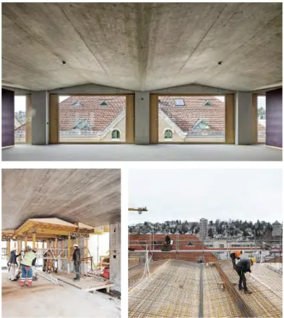
On the other hand, the Namics Headquarters in St. Gallen, Switzerland realized in 2017 (see Figure 8) shows that with reduced geometrical complexity and advanced material handling, in-situ fabrication is a viable approach to produce material-efficient folded structures. The folded slab of the building spans the width of the building (12.87 m) free from any vertical support creating an open office space [43]. For this project, the flow behaviour of concrete was modified to enable casting in-situ with a varying
thickness on a folded plate formwork without the need of counter-formwork (see Figure 8) [44].
Figure 8. In-situ fabricated folded plate structure. Namics Headquarters by Mark Ammann Architekten, St.
Gallen, Switzerland (2017) [45], [46].
2.1.2 Prefabricated folded concrete construction
In general, prefabrication allows for greater control over the concrete material mix and the production process than in-situ fabrication [47]. The predictable quality thus the reliable load-bearing capacity provide better conditions for a highly optimized structural design than on-site fabrication [48]. Custom formworks allow for integrated functions and an increase in the geometrical complexity of the prefabricated elements [49]. The integral joints can be finalized with very little work on-site. Further, the traditional reinforcement methods for large-span structures, such as post-tension cables, remain possible [47]. Next to these numerous advantages, prefabrication is constrained by transportation defining maximal element size and by repetitive designs due to the reuse of the same formwork [11], [50].
For example, the folded concrete structure of the Mühlimatt Sports Education and Training Centre by Studio Vacchini Architetti was realized with prefabrication in 2010 (see Figure 9). This structure consists of 81 precast, load-bearing folded elements assembled to 27 folded frame units that provide a free span of 52.6 m for the sports hall [51]. The formworks for such structurally optimized, large span concrete elements had to comprise intricate features like hydraulic opening mechanism, ventilation for entrapped air and post-tensioned cable positioning aids [52]. Therefore, it became favourable not to discard them after one single use serving the the economics of the fabrication. The resulting standardized geometry is reminiscent of the historical examples of folded plate structures. Nevertheless, despite the repetition in the structural system, the refined design of the single elements provide a unique character to the building [11].
Figure 9. Prefabricated contemporary folded concrete building. Mülimatt Sports Education and Training Centre by Studio Vacchini Architetti in Brügg, Switzerland, 2010 [51].
The South of France TGV Station by Marc Mimram in Montpellier was realized in 2018 with a prefabricated folded roof structure (see Figure 10). The folded roof is made of 115 post-tensioned elements with 5cm thickness and over 18m span [53]. The folded geometry of the roof and the performance characteristics of the concrete mix
used both allowed for significant material savings. The folded elements were prefabricated using 5 different type of formworks and an ultra high performance concrete mix with stainless steel fiber reinforcement [54]. The challenges of the formwork construction (entrapped air, tendon positioning) were similar to the previous example with the Mülimatt Sports Centre. However, for the TGV station, the casting was even more complicated due to the flow properties of the mix design and the perforation of the elements providing obstacles for casting. Regardless the standardized elements the custom perforation pattern could provide variation in the design and brought daylight into the building in a playful manner [53].
Figure 10. Left: Montpellier - South of France TGV Station by Marc Mimram from 2018 [53], Middle: Finished prefabricated elements at their final position on site [54], Right: Formwork removal [55].
2.1.3 On-site prefabricated folded concrete construction
On-site prefabrication means that the formwork and the raw materials are transported to the building site where the elements are cast, demoulded and then assembled at their final place [56]. This method can combine the advantages of both previously discussed construction systems, prefabrication and on-site construction, by freeing the design from transport size constraints and allowing for less constrained segmentation of design driven by mainly the reduction the fabrication complexity. The Confluence Park Pavilion in San Antonio, Texas, USA by Lake Flato Architects was realized in 2018 with this approach (see Figure 11). The pavilion was built from 22 almost 8m tall folded elements with only three unique formworks [57]. The formworks for such elements have been produced in two steps. Firstly, the geometry resembling petals was reproduced from polymer foam blocks with CNC milling. Secondly, fibreglass textiles were laid on top of the foam and were infused with resin to form the composite mould for the concrete (see Figure 11 middle right and right) [58]. The complex geometry of the petals required a customized casting technique where the upper part of the element was left free from formwork and was given a manual surface finish. Despite the repetition of the elements, the apparent complexity of the assembled pavilion is impressive [59].
Figure 11. Top Left: Confluence Park Pavilion in San Antonio, Texas, USA by Lake Flato Architects from 2018 [59]. Top Middle: a single prefabricated petal lifted to its final position. Top Right: the finished formwork on site
[58]. Bottom: the fabrication of the composite formwork on the CNC milled polymer foam [58].
2.1.4 Conflict between design complexity and fabrication efficiency
Contemporary folded concrete structures reveal a conflict between the demand for complexity from the planning professionals equipped with digital design tools and the strive for an efficient production process restricting their design space [60]. They also demonstrate that involving the most commonly used subtractive digital fabrication technologies, such as CNC milling, in the production of complex formworks provide larger freedom of design however it also renders the production more time-, energy- and waste-intensive [13], [61]. Consequently, to increase productivity and reduce costs, the number of customized costly formworks must be reduced for a single project [48].
Thus, academic institutions, and more recently industry, became motivated to initiate research on innovative digital fabrication methods in concrete construction that rethink
the fundamentals of concrete construction: the need for formwork and the casting method [8], [39], [49], [62], [63].
2.2 Research in concrete construction processes
Additive manufacturing has a history that spans almost 40 years [64]. The technology became widespread after the invention of fused deposition modelling (FDM) using melting, a physical change, to construct a digitally designed object in 3D layer-by-layer from polymers [65]. 3D printing of concrete has attracted considerable attention later, only in the last decade [63], due to the difficulty to produce elements at full architectural scale and the complexity of concrete material processing compared to polymer processing [66], [67].
Nevertheless, with the advances of research on the early age properties of concrete numerous new digital concrete fabrication processes appeared that aim to revolutionize the construction industry both in prefabrication and on-site applications [68]–[70].
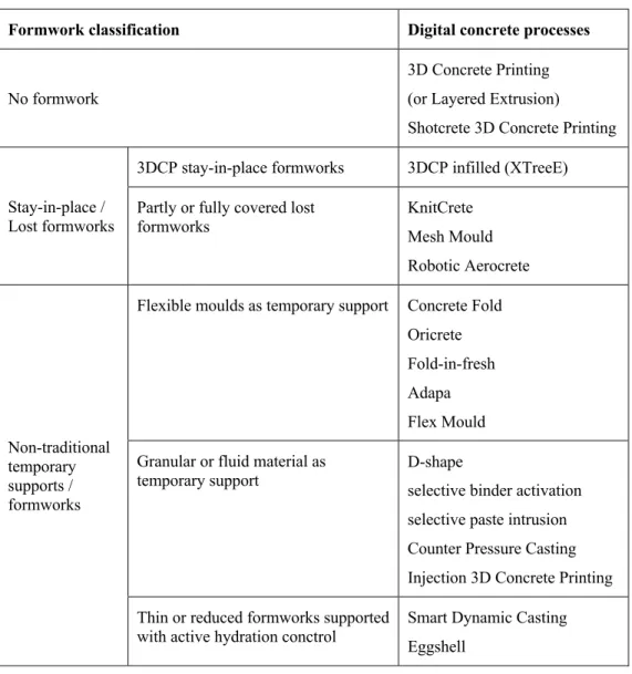
Some of these processes are inspired by already existing digital fabrication principles with different material systems such as 3D printing or binder jetting, others are based on the digitalization of traditional concrete technologies such as casting, slipforming or shotcreting [71]. The classification of the digital concrete processes is rather complicated and different approaches can be observed in the following papers [8], [39], [49], [66], [72], [73]. Table 1 shows the classification used in this thesis by the two most important aspects for this research: the formwork and the concrete processing.
The listed digital concrete proceses will be discussed in detail in the upcoming sections with their advantages and challenges.
Table 1. Classification of alternative formwork systems and the belonging digital concrete processes.
Formwork classification Digital concrete processes
No formwork
3D Concrete Printing (or Layered Extrusion)
Shotcrete 3D Concrete Printing
Stay-in-place / Lost formworks
3DCP stay-in-place formworks 3DCP infilled (XTreeE)
Partly or fully covered lost
formworks KnitCrete
Mesh Mould Robotic Aerocrete
Non-traditional temporary supports / formworks
Flexible moulds as temporary support Concrete Fold Oricrete Fold-in-fresh Adapa Flex Mould Granular or fluid material as
temporary support D-shape
selective binder activation selective paste intrusion Counter Pressure Casting Injection 3D Concrete Printing Thin or reduced formworks supported
with active hydration conctrol Smart Dynamic Casting
Eggshell
2.2.1 To use formwork or not to use formwork?
2.2.1.1 No formwork
The most popular digital concrete process is Layered Extrusion (also called extrusion- based 3D concrete printing, 3DCP) that eliminates the need for formwork [63], [72]. In this process, concrete is extruded through a nozzle that is moved in space with a computer-controlled device to build up material layer-by-layer similar to fused deposition modelling [74]. It was pioneered by Prof Behrokh Khoshnevis from the University of Southern California who industrialized the process under the brand of Contour Crafting with the vision to automate rapid construction of buildings in 2004
[75], [76]. Since then, the process generated an ever-growing research interest both in academia and industry and the first full-scale pilot projects demonstrating its potential have been successfully completed in prefabrication or as on-site construction [77]–[80].
The major advantage of the fabrication method is that it allows for fast production of geometrically complex, structurally efficient geometries as illustrated in the bottom of Figure 12 by the Concrete Choreography project by DBT, ETH Zürich from 2019.
While its main disadvantage is that it cannot be combined with traditional reinforcement techniques unless the concrete print is only used as stay-in-place formwork [81]. The efficient integration of alternative reinforcements is an ongoing topic of research [82].
Figure 12. Top Left: Contour Crafting process [76]. Top Right: Layered Extrusion process [81]. Bottom:
Concrete Choreography project from DBT, ETH Zürich featuring geometrically complex concrete columns produced with Layered Extrusion [81], [83].
Another formwork-free layer-by-layer digital fabrication method is Shotcrete 3D printing (SC3DP) that is a robot-assisted concrete spraying technology developed at TU Braunschweig in 2017 [84]. The institute recently published a video (see a
screenshot in Figure 13) demonstrating the 3-step fabrication of a double-curved reinforced concrete wall in collaboration with the Leibniz University Hannover and the TU Clausthal [85]. In this process, first, the rough geometry is built up with undulations that define the position of the vertical reinforcement. First, the horizontal reinforcement is added manually every few layers. Then, the vertical rebars are placed and the structure could be covered with an additional layer of sprayed concrete. As the last step, subtractive robotic surface smoothing is performed. The main advantage of this process is to incorporate traditional structural reinforcement and to provide extended geometrical freedom compared to 3DCP for printing cantilevers and overhangs without additional support structures [84], [86].
Figure 13. Fabrication of a double curved reinforced concrete wall with Shotcrete 3D printing. Left: The first step of creating the undulated geometry with SC3DP. Right: The second step of concreting with the manually placed
reinforcement still visible [85].
However, it is important to point out that the absence of formwork that on the one hand reduces cost and waste, on the other hand, hasa significant effect on the surface characteristics. The lack of formwork can also affect structural performance and requires that the concrete becomes self-supporting immediately after deposition [62], [68], [71]. Firstly, the material needs to be pumpable, extrudable or sprayable, then the extruded concrete or sprayed deposit has to have high enough yield stress to keep its shape right after leaving the nozzle, and finally, rapid strength increase is required to support the consecutive layers on top [69], [71], [87]. Then, the layered character of the surface is defined by the fabrication method and it can only become completely smooth with additional post-processing techniques that increases the complexity of fabrication and costs [88], [89]. Additionally, water evaporation on the surface of the extruded concrete filaments can cause cold joints, weak bonds between layers, leading to decreased structural performance. In the case of reinforced elements, cold joints are
low resistance areas for chloride ingress exposing the rebars to a higher risk of corrosion [90], [91].
Although both processes show potential for the fabrication of thin folded concrete elements none of these was investigated for this purpose so far.
2.2.1.2 Stay-in-place/lost formworks
Printed stay-in-place formworks infilled with concrete
The following processes use stay-in-place formworks, which are not removed after the setting of the concrete. Thus, the formwork becomes an integral part of the finished structure, it can enhance functionality or have an aesthetic function [62].
Stay-in place formworks printed with 3DCP can be infilled with foamed concrete as insulation or with structural reinforced concrete that contains metal fibre or traditional reinforcement. This method combines the geometrical possibilities opened up by formwork-free construction with full structural or increased thermal performance [77], [92]. In 2019, the start-up XTreeE used 3DCP to prefabricate the stay-in-place formwork of a 12m high telecommunication tower with branching design segmented into 6 pieces (see Figure 14). These parts will be shipped to Guadeloupe, stacked on top of each other and filled with UHPFRC to create a structure that can resist the harsh environmental conditions of earthquakes and hurricanes [93].
Figure 14. Left: The 3D Concrete Printing process of XTreeE. Middle: One of the six segments of the telecommunication tower. Right: The design of the 5G tower in Guadaloupe [93]
Party or fully covered lost formworks
Compared to the previous examples where the lost formwork defines the surface appearance and confines the subsequently applied concrete, other technologies cover it partly or completely. For example, in the process called KnitCrete by BRG, ETH Zürich from 2016, the lost formwork is a custom-shaped textile produced with a CNC knitting machine, tensioned on a temporary support structure and sprayed on one side with rapid hardening calcium aluminate cement paste [61], [87]. Then concrete is applied on top of the cement coating with traditional methods to create a thin concrete shell structure [94]. The first pavilion constructed with KnitCrete called Knit Candela in Figure 15 was constructed in 2019 as a doubly-curved concrete shell with almost 50 m2 surface area [95], [96].
Figure 15. Knit Candela pavilion produced with a CNC knitted lost formwork [95].
Although the potential to use the textile as reinforcement was given, in KnitCandela it was not exploited yet. In contrast, the following two processes, Mesh Mould and Aerocrete use semi-permeable mesh structures as lost formwork that becomes reinforcement after concreting.
Mesh Mould is a fully automated bending and welding process for the fabrication of reinforcement cages with custom geometries that allow for the fabrication of fully load- bearing concrete components that has been developed by GKR, ETH Zürich in 2018 (see Figure 16) [97]. The reinforcement cage is a permeable leaking formwork that party allows the concrete infill to protrude through its perforations during casting [98].
The surface of the element is finalized with manual trowelling. The process was demonstrated in 2018 with a doubly-curved structural wall in a large scale demonstrator called NEST building [38], [97].
Figure 16. Mesh Mould robotically fabricated welded metal lost formwork that also functions as reinforcement [97].
Robotic AeroCrete in Figure 17 is an automated shotcreting technology developed at ETH Zürich in 2018 that sprays concrete containing short fibres on a permeable mesh to produce reinforced shell structures [99]. Its first demonstrator proved the possibility to coat the reinforcement despite its permeability thanks to the carefully selected ratio between the size of the openings in the mesh and the length of the short fibres included in the concrete. However, a significant amount of concrete was wasted during spraying thus decreasing the material efficiency of the process.
Figure 17. AeroCrete robotically shotcreted prototype and the different surface structures obtained with the process [99].
In summary, most of the technologies involving stay-in-place or lost formworks provide the possibility to include reinforcement thus produce fully functional structural concrete elements. However, their numerous process steps increase the complexity of fabrication and require manifold technical knowledge.
The first demonstrator of the Robotic Aerocrete process had a folded geometry also resembling the concrete petals of the Confluence Park, thus it can be stated that the
process has great potential to produce thin folded structures with custom geometries, although with decreased levels material savings and limited smoothness of the final surface unless an additional surface finish step is added (see Figure 17).
2.2.1.3 Non-traditional temporary formworks
The fabrication methods of the last category use non-traditional supports or formworks that are removed during or after the production process [62]. Most of the research projects focusing on the fabrication of thin folded concrete elements belong here.
Flexible moulds as temporary supports
The first group of projects use reconfigurable, flexible formworks to achieve a ceratin range of shapes. For example, the following projects from RWTH Aachen demonstrate three different approaches to the production of textile reinforced concrete folded structures with these non-traditional reconfigurable formworks.
The Concrete Fold project from 2014 applies a manual manufacturing process to produce non-structural undulated façade elements from Concrete Canvas (see Figure 18) [100]. It uses a fabrication bed as formwork that can induce different curved or angular deformations to the concrete canvas while it sets due to the contact with water.
However, this fabrication method is limited by the dimensions of the folding bed and the directionality of its folding components [11].
Figure 18. Concrete Fold from RWTH Aachen showing the manual labour required for producing the elements on the right [100]
The Oricrete project from 2013 enables casting the unfolded geometry in-plane off-site and then folding it to a 3D structure on-site (see Figure 19 Left) [101]. The Oricrete
project consists of two interdependent parts: a digital modelling framework and a physical construction method for folded plate structures [101]–[103]. The modelling framework provides the design tool and the digital environment for the construction method thus allows for form-finding, structural optimization and simulation of the folding process. The fabrication process starts with producing the unfolded structure flat by leaving the digitally defined crease pattern flexible and free from concrete. After the setting of the concrete the concrete-free crease pattern act as hinges between the rigid faces. The element is transported to the building site, and laid on a temporary scaffolding that defines its final folded shape. Then its creases are grouted to fix the fold angles and finalize the structure. The Oricrete process was demonstrated in both model and one-to-one scale with thin folded shell vaults and canopies that show either single or double curvature (see Figure 19 Left) [101], [104].
Figure 19. Left: Bike shell-ter produced with the Oricrete technology [105]. Right: Fold-in-fresh, the newest direction of Oricrete producing segments of a barrel vault [106].
The Fold-in-fresh technology from 2019 is a recent direction of the Oricrete project that aims to simplify the fabrication process by folding a freshly cast textile-reinforced concrete plate into a folded geometry before it hardens (see Figure 19 Right) [106]. It uses a foldable formwork that consists of triangular faces connected by hinges. The fabrication process starts with casting a concrete layer on the unfolded flat formwork, then the concrete and the formwork is folded up together from underneath with wedges.
The method was demonstrated on a vault structure built up from identical segments produced individually with the process [106].
The research projects Concrete Fold, Oricrete and Fold-in fresh show potential to eliminate the need for elaborate, spatial formworks for folded plate constructions, however, they all need processing steps that require extensive human labour.
Additionally, their structural potential is limited by the performace of the textile reinforcement.
The Adaptive MouldTM by Adapa (see Figure 20 Left) from 2013 also use principle of forming concrete in a fresh state similar to fold-in fresh, however, instead of folded elements, it focuses on the prefabrication of single or double-curved panels [107], [108]. The core of the technology is a grid of digitally controlled actuators underneath the surface of the mould that allows for fast and accurate reconfiguration of its shape.
Up until now, the technology was mostly used indirectly for the fabrication of custom formwork inlays instead of producing unique concrete elements.
Figure 20. Left: The Adaptive MouldTM of the start-up Adapa [107]. Middle:TailorCretefabrication setup [108].
Right: Flex Mould pavilion with double curved concrete surfaces from TU Delft [109].
The research project Flex Mould from TU Delft from 2017 (Figure 20 Right), similar to the Adaptive Mould of Adapa, uses extendable actuators to define the geometry of the one-sided flexible mould to produce curved precast elements [109], [110]. The Flex Mould project also discusses how cracking can be avoided during deliberately imposed deformation due to the plastic strain capacity of the concrete at a specific yield stress range. In the most recently studied version of this process, the position of the actuators is fixed before fabrication and 3DCP is used to define the edges of the elements on top of the mould for subsequent casting [110]. Both the fabrication method of Adapa and the Flexible Mould project show the possibility to include thin steel rebars, glass fibre textiles or mixed fibres during fabrication. Although these processes demonstrate a high level of automation, they are not widely used due to their expensive fabrication beds with high mechanical complexity.
Granular or fluid materials as temporary support
The next group of technologies uses granular or fluid materials to provide temporary support during fabrication. The most common digital fabrication method in this category is particle bed 3D printing that applies the principle of a pioneering additive manufacturing technology for polymers, selective laser sintering [111], on construction materials [112]. In this process, the elements are built from discrete layers by first spreading loose particles then bonding them only at specific areas by the digitally controlled selective deposition of a liquid or a paste. Two major approaches exist for producing concrete components: 1) selective binder activation using water as an activator on a loose mixture of aggregates and binder(s) and 2) selective paste intrusion injecting cement paste as activated binder into a bed of aggregates [112], [113].
Figure 21. Left: D-shape process. Right: A 3D printed footbridge realized in collaboration between D-Shape and IAAC, Barcelona [114].
The publication of Pegna from 1986 describing cement bed printing is the earliest reference in literature for digital fabrication with concrete [115]. However, the feasibility of the selective binder activation for producing large scale architecture was proven only later by the founder of D-Shape, Enrico Dini with a 3D printed footbridge in 2016 that created 12m span and featured a complex design based on optimization algorhythms [114], [116]. While the scale of the prints was a milestone for architecture, it is important to observe that the 3D printed elements of the bridge were supported by a load-bearing steel structure. Since then both process variants have been extensively researched by several research institutions such as TU Braunschweig, Swinburne University of Technology or Columbia University to name a few [112], [117], [118].
The research interest is probably due to the high resolution and the geometrical freedom for cantilevers and undercuts offered by these processes. However, their disadvantages
do not make them favourable for producing folded structures with the limited element size due to the volume of the particle bed, laborious post-processing to remove the unbound particles and the risk of decreased structural performance due to voids from entrapped air.
The next method is Counter Pressure Casting that was developed at ETH Zürich in 2017. It uses the aggregate bed around thin 3D printed polymer formwork to counteract the formwork pressure during casting [119]. This process was demonstrated with the skeletal optimized structure of a concrete canoe cast from UHPFRC (see Figure 22 Left). The aggregate placement in this process does not pose any technical challenge in contrast to particle bed 3D printing. Further, the removal and recyclability of the aggregates are easier, however, it introduces additional fabrication steps with the production of 3D printed formworks and their removal. Nevertheless, with respect to possible industrial application, all the different steps have relatively low technological barriers to overcome and the process can, therefore, be expected to become robust.
Figure 22. Left: Topologically optimized structural frame of a concrete canoe produced with counter-pressure casting [119]. Right: Sub-Additive 3D concrete printing [120].
Similar to the previously discussed flexible mould concept, aggregate piles can also be used as one-sided moulds for producing curved concrete elements with custom geometries. In Sub-Additive 3D concrete printing from Cornell University from 2018 (Figure 22 Right), the geometry of the pile is constructed with a robotic arm equipped with simple tools that can move the aggregates and then the concrete is printed on top [120]. The process is demonstrated on a segmented arch prototype [121]. Although the principle of the process sounds simple, the arrangement of the aggregate bed is challenging and requires feedback loops from a 3D scanning device to maintain accuracy.
The last example in Figure 23, Injection 3D concrete printing (I3DCP) from TU Braunschweig from 2020, benefits from the confinement from a gel instead of a granular material system [122]. It applies the principle of Rapid Liquid Printing developed at MIT, Cambridge in 2017 [123] or Fluid Cast from AA, London from 2009 [124] for spatial concrete printing. The I3DCP process uses two fluid materials with similar rheological properties, to robotically inject one into the other in a manner that the injected material keeps its position in the surrounding other material. The method is investigated with concrete as injected material and a gel-like non-hardening suspension as surrounding material or the other way around. Further, this process also provided a possibility to create functionally graded concrete structures by using concrete with different properties for the injected and surrounding medium [122]. This novel approach provides the possibility of previously unseen spatial freedom for concrete extrusion and high building rates. However it also has to cope with the size constraints and the scalability of the tank similar to the aggregate bed for Counter Pressure Casting. Here, the possible element height (weight of the part over a unit area) is limited by the yield stress obtainable from the gel. The surface quality and the bonding between the layers, thus the structural performance remains questionable.
Figure 23. Injection 3D concrete printing in the gel on the left and a prototype printed in the combination of gel and sand on the right [122].
Thin or reduced formworks supported with active hydration control
The last group of processes discussed in this chapter, Eggshell from 2018 and Smart Dynamic Casting from 2012, belong to the Digital Casting Systems (DCS) developed at GKR, ETH Zürich [62]. They require active hydration control for the concrete to maintain the functionality of their non-traditional small or thin formworks. The concrete used in the DCS processes is manipulated with chemical admixtures to be
![Figure 7. In-situ fabricated formative folded concrete buildings. Left: Chapel in Valleaceron [42]](https://thumb-eu.123doks.com/thumbv2/1library_info/5298438.1677546/21.892.203.695.642.853/figure-fabricated-formative-folded-concrete-buildings-chapel-valleaceron.webp)
![Figure 9. Prefabricated contemporary folded concrete building. Mülimatt Sports Education and Training Centre by Studio Vacchini Architetti in Brügg, Switzerland, 2010 [51]](https://thumb-eu.123doks.com/thumbv2/1library_info/5298438.1677546/23.892.247.645.494.937/prefabricated-contemporary-mülimatt-education-training-vacchini-architetti-switzerland.webp)
![Figure 10. Left: Montpellier - South of France TGV Station by Marc Mimram from 2018 [53], Middle: Finished prefabricated elements at their final position on site [54], Right: Formwork removal [55]](https://thumb-eu.123doks.com/thumbv2/1library_info/5298438.1677546/24.892.190.705.409.944/figure-montpellier-station-finished-prefabricated-elements-position-formwork.webp)
![Figure 18. Concrete Fold from RWTH Aachen showing the manual labour required for producing the elements on the right [100]](https://thumb-eu.123doks.com/thumbv2/1library_info/5298438.1677546/34.892.167.724.783.994/figure-concrete-aachen-showing-manual-required-producing-elements.webp)
![Figure 19. Left: Bike shell-ter produced with the Oricrete technology [105]. Right: Fold-in-fresh, the newest direction of Oricrete producing segments of a barrel vault [106]](https://thumb-eu.123doks.com/thumbv2/1library_info/5298438.1677546/35.892.176.719.496.706/figure-produced-oricrete-technology-direction-oricrete-producing-segments.webp)
![Figure 20. Left: The Adaptive MouldTM of the start-up Adapa [107]. Middle:TailorCretefabrication setup [108]](https://thumb-eu.123doks.com/thumbv2/1library_info/5298438.1677546/36.892.177.730.427.641/figure-left-adaptive-mouldtm-start-adapa-middle-tailorcretefabrication.webp)
![Figure 21. Left: D-shape process. Right: A 3D printed footbridge realized in collaboration between D-Shape and IAAC, Barcelona [114]](https://thumb-eu.123doks.com/thumbv2/1library_info/5298438.1677546/37.892.211.684.474.688/figure-process-right-printed-footbridge-realized-collaboration-barcelona.webp)
![Figure 22. Left: Topologically optimized structural frame of a concrete canoe produced with counter-pressure casting [119]](https://thumb-eu.123doks.com/thumbv2/1library_info/5298438.1677546/38.892.173.718.569.762/figure-topologically-optimized-structural-concrete-produced-counter-pressure.webp)
