Virtual Reality &
Physically-Based Simulation
VR Displays,
Stereo Rendering,
Display Issues
Depth Cues
§
Motion parallax: apparent motion of objects relative to each other, when observer moves§
Occlusion§
Stereopsis (binocular/stereo vision)§ Important, but not the most important depth cue
§
Accommodation & convergence§
Defocus blur (a.k.a. blur gradient)§
Perspective (see CG1)§
Lighting & shading§
Relative size / familiar size§
Texture gradientBinocular/Stereoscopic Vision / Stereopsis
§
Focus = adjustment of the eyes' lenses to adapt to different distances§ So that the fixated object appears sharp on the retina
§ A.k.a. accomodation
§
Convergence = counter-rotating eye movement (around the vertical axis), so that the optical axes of the eyes intersect at some point (fixation point)§ So that the fixated object appears on the center of the retina (has highest resolution)
§
Stereo blindness: ~10% of general population§
Some people can actually turn their eyes to divergence:§
Convergence causes disparity δ between corresponding points on the retinas:Horopter
d1
d2
+
- +
-
a g
= 2 1 = ↵
The Shape of the Horopter
§
Mathematical construction ⟶ Vieth-Müller Circle = theoretical locus of points in space that stimulate corresponding retinal points
§
Measuring the horopter with the "ApparentFronto-Parallel Plane"
method:
§ Subject is asked to arrange a series of objects so that there appears to be no depth difference between them
mmmmcm
Panum's Fusional Area
§
There is a zone/range of depth around the horopter, where the brain is able to fuse the double image of an object→ Panum's Area of Fusion
Human
3D
2D 2D
Bunny
Limitation of Human Stereopsis
§
Stereoscopic vision works just up to a few meters (< 6 m, ca.)§
Does not work in the left & right periphery:The History of Stereo Images
§
Euklid (4th century BC)§
Sir Charles Wheatstone (1838 )§
1860: 1 million Stereoscopes sold§
1950-ies:■ Today
How to Project Stereo With Only One Display Surface?
§ One channel, two senders & receivers → need some kind of multiplexing
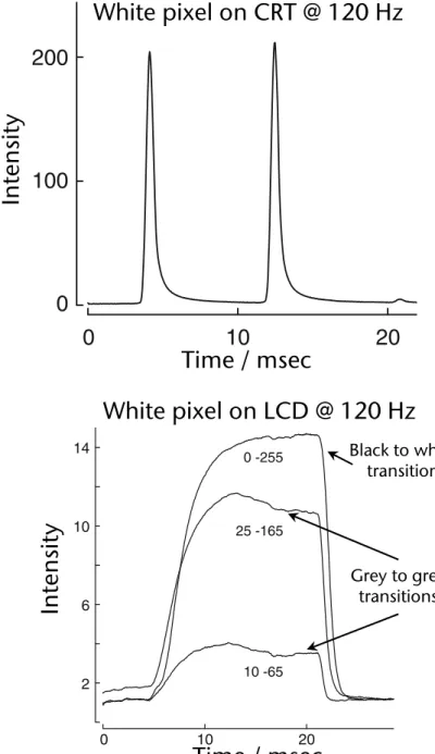
1. Temporal Multiplexing ("active stereo"):
§ Typically 1 projector (e.g. monitor)
§ Project/render alternatingly left/right image
§ Synchronously, switch left/right glass of shutter glasses to pass-through
§ Shutter glasses run with 120 Hz → 60 Hz framerate
2. Multiplexing by polarization ("passive stereo"):
§ Usually 2 projectors displaying on same surface
§ Project left/right simultaneously but with different polarization of the light
§ Polarization glasses let only left/right images pass, resp.
§
Kinds of polarization:1. Linear polarization:
- Any direction perpendicular to direction of travel of light
2. Circular polarization:
- Left-handed / right-handed polarization
Demo
http://www.colorado.edu/physics/2000/applets/polarization.html
"Color Multiplexing"
§
Simple version: Anaglyph stereo (red-green stereo)Creating Anaglyph Images
§
Monochrome images:§ Render left & right images
§ Convert to grayscale ⟶ L, R
§ Merge into red & cyan anaglyph image I(r,g,b) by assigning
§
Full color anaglyph images:§ Render left & right images, but do not convert to grayscale ⟶ L, R
§ Merge into red & cyan anaglyph image:
I (r ) = L , I (g , b) = R
Multiplexing by Wavelength (Infitec)
§
Generalization of anaglyph stereo:§ Partition whole spectrum into 6 (narrow) bands
§ Left & right eye get filters with interleaving band passes
§ Other names: Dolby3D, spectral comb filter
§
Tricky part: color fidelityLeftRight
620 nm
λ
460 nm
540 nm 520 560
440 480
600 640
λ
λ
λ
λ
λ
≈
≈
≈
Improvement: Utilize Color Metamerism
Courtesy Infitec(infitec.net)
By way of metamerism, the same "color" of 460 nm light can be created by shining light consisting of 440 and 480 nm into the eye
Autostereogram (Single Image Stereogram)
§
"Magic Eye" images are patterns constructed such that corresponding points convey depthUnderlying "depth image"
Curiosity: Stereoscopic Effect Based on the Pulfrich-Effect
§
The Pulfrich effect:§ Discovered by Carl Pulfrich, German physicist, 1922
§ Dark stimulus in the eye arrives later in the brain than a bright stimulus
§
Viewing instructions: put sunglasses or similar darkening filter over one eye, the other eye remains nakedhttp://www.youtube.com/watch?v=1mnWI_u_zBg
Immersive Displays
§
Head-Mounted Displays (HMDs)§ Head-Coupled Displays (HCDs)
§
Immersive projection displays (IPDs)§ Autostereo Monitor
§ Desktop setups
- E.g. Autostereo monitors, zSpace, or"reach-in"
§ "Powerwall"
§ Workbench
§ Cave
§
"Exotic" displays:A.k.a. World-Fixed Displays
Stereo Monitor
§
Sometimes called "Fishtank VR"§
Advantages:§ Inexpensive
§ Resolution up to 1900 x 1600
§ Well accepted by users (?)
§ No special requirements on the environment/setting
§ Some 3D capabilities
§
Disadvantages:§ Small Field-of-View (FoV)
§ Very little immersion
§ Very limited working volume
§ "Stereo frame violation" is very
common zSpace
52'' Autostereo Display
§
Interesting things you can do with a simple monitor: the "Reach-in idea"§
The problem with a small FoV: there is practically no immersion!Head-Mounted Diplays (HMD)
§ First "true" VR display
§ Technologies / characteristics:
§ HMDs using LCDs or OLEDs
§ Weight:
- Small FoV →lightweight; large FoV → heavy
§ Advantages:
§ Kind of a "surround display"
§ In theory, very good immersion
§ No stereo frame violation
§ Large working volume
§ Almost no special requirements on the
Virtual Research
Around 1992Around 198
Other Models (as of 2017)
Oculus VR / Facebook HTC Vive
Sony's PlayStation VR
NEO VR by Immersion
"Sword of Damocles" (1965)
Moon by Royole
Disadvantages of HMDs
§
Uncomfortable when used for a prolonged time ("invasive interface")§
Distortions (can be corrected somewhat by pre-distortion)§
Real environment is shut off (good for immersion, bad for collaboration and self-embodiment)§
Manipulation of real controls is difficult (e.g., in mockup of cockpit)§
Every participant needs an HMD (bad: expensive, good:everybody has correct perspective in VE)
The Field-of-View Problem of HMDs
200o
60o 120o
Common HMDs Human
Fied of View
Monocular Binocular
Human visual field
The Resolution Problem of HMDs
§
Human visual acuity:§ 1 photo receptor (cone) = 1 arc min = 1/60 degree
§
Display needed for a "retina" HMD:§ 150o x 135o with 1/60o resolution = 9000 x 8100 pixels per eye
§
Challenges:§ Bandwidth: moving the data at 60 Hz from GPU to display
§ Miniaturize display panels with 73 Mio pixels
5 arc min
HMD with Eye Tracking
§
Potentials:§ "Foveated rendering"
- Requires end-to-end latency of < 10 ms
§ Control game using eye gaze direction
§
Dynamically move the zero-parallax plane?§
Control focus depth for depth-of-field rendering?§
Make eye contact with virtual avatars (NPC)?§ So they "notice" and look back at you
§
Shoot enemies in games just by looking at them?My Vision
§
Wireless HMD with very wide field-of-view and SLAM-based tracking like HoloLens§
Can someone build that for me please?Head Coupled Displays (HCD) – Out-Dated
§
HCD = HMD mounted on a"boom"
§
Advantage of HCDs over HMDs:§ Possible to quickly "take the display off" for a moment; or
users can just take a "quick peek"
into the VE
§ Low weight on the head
§ Extremely good tracking comes built-in
§
Disadvantages compared to HMDs:§ Smaller working volume
§ One hand is always occupied
§ Inertia
à
Failed to gain market shareImmersive Projection Displays / Technology (IPD / IPT)
§
Idea is (somewhat) similar to cinema theaters§
Setup: 1–6 walls on which VE is projected§
Powerwall = 1 wall (e.g., 3x6 meters)§
Workbench = 1 horizontal display surface (table)§
Holobench, L-Shape = 2 display surfaces, 1 vertical, 1 horizontal§
Cave = 3–6 wallsLarge-Screen Projection Walls (Powerwalls)
© Immersion
§
"HeyeWall" (Darmstadt):§ 24 tiles, 48 PCs
§ Total resolution: 18 Mio pixels (6144 x 3072) in stereo
Example Application: Virtual Conference Room
Result: 1 shared workspace, by way of coherently adjoining
"desktop IPDs"
Workbench, L-Shape, Holobench, etc.
Holobench Workbench
Cave
3-wall cave
Schematic of the arrangement of the mirrors
5-wall cave, FhG-IGD, Darmstadt
, Alborg, DK
5-sided CAVE at University RWTH Aachen
RealityDeck - Immersive Giga-Pixel Display
§
308 x 30" LCD displays§
2560x1600 resolution per display§
1.5 Giga pixels of resolution in total§
40'x30'x11' physical dimensions§
85 dual quad-core, dual-GPU cluster nodeshttp://www.cs.stonybrook.edu/~realitydeck/
Curved Screens
§
Usually, with wall-sized screens (curved or not), some kind of edge blending and color correction between projectors isnecessary
Curved Screen made out of 3D-TVs
§
Idea: construct the walls of a Cave / curved powerwall out of a (small) number of 3D TVs§
Advantage: reconfigurable relatively easily (just put the walls on wheels)Personal Domes
§
Example: Wii + Dome + MacBook ProSource: Paul Bourke, University of Western Australia, http://local.wasp.uwa.edu.au/~pbourke/
§
A modern "Sensorama":Immersa-Dome from Aardvark Applications
Advantages and Disadvantages of IPTs
§ Advantages:
§ Large resolution
§ Large field-of-view
§ "Non-invasive"
§ No isolation of the real world
§ (Can accomodate several users)
§ Cave: turning the head results in small changes of the images à problem of latency is reduced / not so prominent
§ Disadvantages:
§ Size
§ Price (lots of projectors, lots of graphics cards)
Retinal Displays
§
Idea:§ Use the human retina as the display
surface (all images from the outer world end up there anyway)
§ Use a laser to write the image by scanlines into the eye
§
Advantages:§ Can be miniaturized (potentially)
§ High contrasts, high brightness
§ Good for see-through displays, bad for VR
§ Small power consumption
Video Source
Drive Electronics
Laser Intensity
Modulator Beam
Scanning Optical Projection
Design study
Holographic / Volumetric / POV Displays
§ Hologram = can reconstruct real 3-dimensional image
§ Advantages:
§ Provide correct perspective/view from every angle!
§ Coherence between accomodation and convergence
§ Depth of field (Tiefen(un-)schärfe)
§ Holographic displays: algorithmic computation of holograms
§ Problems:
§ Staggering amount of computational work
§ Colors
§ Volumetric displays: voxels are projected onto a a rapidly rotating surface covering a volume
§
A.k.a.: Persistence of Vision Displays§ Problems:
§ Size of data (e.g. 100 mega-voxels = 1000x1000x100 display resolution)
§ Occlusions?
§
Example volumetric display:§ 198 x 768 x 768 » 100 million voxels
§ Frame rate: 20 Hz
Unconventional Displays and Display Surfaces
§ Fog ("fog screen"):
§ Laminar, non-turbulent air flow
§ Water droplets are "sandwiched"
within the air flow
§ DisplAir: dry fog
FogScreenDisplAir
§
The "Janus" display of KAIST, Korea:§ Utilizes persistence of vision
§ See-through display with touch interaction for collaboration
§ Each person on either side gets their own, possibly different image
§
"Everywhere displays":Recap: Perspective Projection in OpenGL
glFrustum( left, right,
Stereoscopic Projection
§
Parallax on the screen→ disparity in the eyes
§
Wrong way: converging view vectors§ Problem: vertical parallax!
"Glass pane"
l r r
l
+
-
Projection planes
Parallax Not Well Done
Correct Stereoscopic Projection
§
Parallel viewing vectorsàOff-center perspective projection (a.k.a. "off-axis projection")
§ Important stereo parameters:
§ IPD and ZPP
Projection Planes (near frustum planes)
Cyclop's eye
Zero parallax plane (ZPP)
("horopter", a.k.a. "fusion distance")
Eye separation (a.k.a. interpupilary distance, IPD)
§
Thought experiment: imagine a single line emanating from 1m in front of you, away from you to infinity§ What stereo image do you get?
§ What happens, if the IPD increases?
§ What happens, if you move the ZPP closer or further away?
G. Zachmann Virtual Reality & Simulation WS 8 November 2017 Displays and Stereo Rendering 86
Hypo- and Hyper-Stereo
§
In monoscopic filming/display, cameras just have these parameters:§ Field-of-View, focal length (film), …
§
In stereoscopic filming/rendering, cameras in addition have:§ Interaxial separation (a.k.a. IPD)
§ Zero-parallax plane
§
Hypo-Stereo: Interaxial < IPD ⟶ dwarfism effect§
Hyper-Stereo: Interaxial > IPD ⟶ gigantism effect§
Can make sense for macro/micro scenesInteraxial Separation between lenses, a.k.a. Stereo Base, a.k.a. Interocular separation,
(a.k.a. IPD for human eye)
The Audience Sizing
New Constraint
– A 2D camera has a focal length – A 3D camera rig has a Size
– The audience identifies with camera size
Hypo Stereo: Audience Shrink
Inter-Axial set to less than Human I.O.
Hyper Stereo: Audience Giantism
Inter-Axial set to more than Human I.O.
Can be used for storytelling
l
Computation of the Frustum
§ Given: i = interpupilary distance ÷ 2, w/h = aspect ratio, a = horizontal FoV , n = near plane , z0 = zero-parallax depth
§ Task: determine left/right/top/bottom for glFrustum()
§ Assumption (for now): no head tracking → cyclop's eye is in front of the center of the viewport
§ Example:
compute left for left eye
w h
i
a
l' lc
l
c= n tan ↵
2
Video: Stereo Projection in the Analog World
Problems with Stereo Rendering: Depth Aliasing
Stereoscopic voxel 2
2
2
2
2
2
2
Convergence-Focus Conflict
§
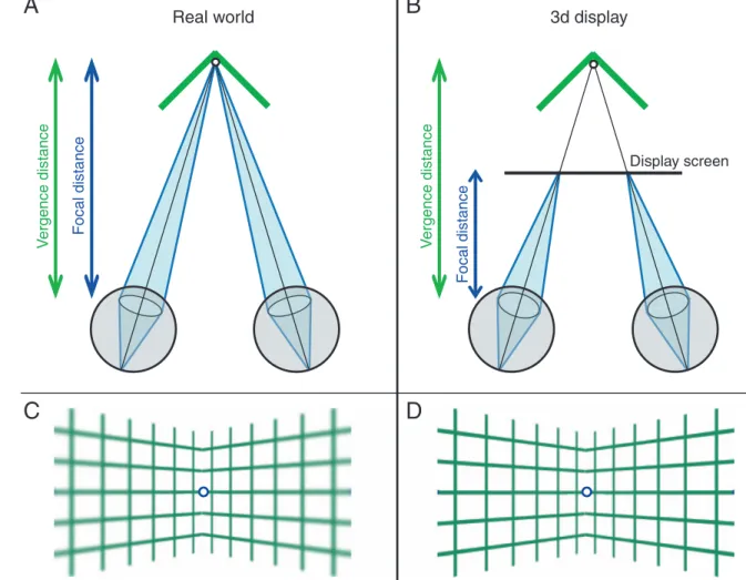
Experimental evidence shows: the brain computes a weighted average of multiple depth cues, including focal depth§
With stereoscopic displays, our eyes receive inconsistent depth cues:§
Effect: in a Cave or Powerwall, near objects appear more distant than they areWatt, Akeley, Ernst, Banks: "Focus cues affect perceived depth", J. of Vision, 2005]
Focal distance Vergencedistance
Real world
Focal distance Vergencedistance Stereo display
G. Zachmann Virtual Reality & Simulation WS 8 November 2017 Displays and Stereo Rendering 93
§
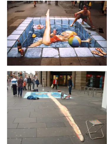
This problem is potentially aggravated in projection-based AR, even if geometric correction by eye tracking is doneVRST’17, November 8-10 2017, Gothenburg, Sweden XXX
• a psychophysical experiment to validate the e�ects of stereo- scopic parallax on depth perception when stimuli are pro- jected onto di�erent surfaces, and
• a con�rmatory study to verify the �ndings with more eco- logically valid projection-based AR stimuli.
The results provide important insights in how depth is perceived in stereoscopic projection-based AR setups between di�erent user groups.
The remainder of this paper is structured as follows. Section 2 provides background information regarding the �eld of stereo- scopic projection-based AR, depth perception and visual con�icts.
Section 3 describes an experiment, in which we analyze the ef- fects of stereosc+pic parallax on how humans perceive matching depths of objects that are stereoscopically projected on di�erent surface planes. Section 4 describes a con�rmatory study, in which we further analyze the factors with a more realistic visual stimu- lus. Section 5 concludes the paper and discusses future research directions in this �eld.
2 RELATED WORK
In this section, we summarize previous work in the �eld of projec- tion onto real-world surfaces, vergence-accommodation con�icts as well as depth perception in virtual environments (VEs).
2.1 Stereoscopic Projection-based SAR
At the end of the last century, Raskar et al. [19] demonstrated a prototypic implementation of projection-based AR by registering a virtual 3D model with the underlying 3D physical object in order to overlay additional virtual content. Since then, several projection- based AR setups have been introduced and revised, for example, Shader Lamps [21], O�ce of the Future [20] and Emancipated Pix- els [28]. In most of these setups 2D textures were projected onto a 3D geometry, i. e., the virtual information is displayed in mono- scopic 2D onto the physical surface. More recently, Jones, Benko and Wilson introduced the RoomAlive [14], IllumiRoom [13] and Mano-a-Mano [2] setups, which allow to monoscopically display virtual objects at any arbitrary 3D location. However, most of the mentioned setups do not provide stereoscopic display, but rather rely on monoscopic cues such as view-dependent perspective to convey the sense of a spatial presence of the virtual object.
Using stereoscopic display allows to project virtual 3D objects onto real-world 3D geometry, for instance, physical block models of buildings in architecture or exhibits in interactive museums1. How- ever, in such environments even a single object could be projected onto di�erent surfaces with varying depths, orientations or forms as illustrated in Figure 1. Furthermore, with S3D each eye sees a di�erent perspective of the same scene by means of S3D technology, such as shutter glasses. This requires display of two distinct images
S3D glasses
S3D projector
physical model virtual 3D
object
projections of object focal distanc
e vergence
distanc e
tracking camera
Figure 1: Projection-based AR in which a virtual 3D ob- ject is projected onto two di�erent surfaces. In S3D the focal distance typically varies from the distance to where the eyes converge resulting in the well-known vergence- accommodation con�ict. The camera is used for tracking the user’s head in order to provide a correct S3D perspective.
In contrast, objects that appear in front of or behind the projec- tion surface usually result in vergence-accommodation con�icts described in the next section.
2.2 Vergence-Accommodation Con�ict
In a natural viewing situation, the vergence stimulus and focal stim- ulus are at the same distance and therefore the vergence distance, i. e., distance to the object to which the eyes converge, and the focal distance, i. e., distance to the object at which the eyes focus to sharpen the retinal image, are consistent with each other. There is a tight correlation in natural viewing conditions, and hence ver- gence and accommodation are neurally coupled [9]. More precisely, changes in accommodation evoke changes in vergence (i. e., accom- modative vergence), and changes in vergence evoke changes in accommodation (i. e., vergence accommodation). However, when viewing a projection-based AR scene with stereoscopic display, the situation is di�erent. As illustrated in Figure 1, the focal distance is �xed at the distance from the eyes to the surface at which the two images for left and right eye are projected, whereas the ver- gence distance di�ers depending on the position in space where the object is simulated. This discrepancy results in the well-known
G. Zachmann Virtual Reality & Simulation WS 8 November 2017 Displays and Stereo Rendering 94
§
Another depth cue: blur§ The eye (brain) can estimate (relative) depth from the amount of blur
§
If no depth-of-field is being rendered, then our eyesperceive different depth cues:
pupils, errors of 1D and 2D cause nearly two- and ten-fold reductions in stereoacuity, respectively (Odom, Chao, &
Leys, 1992; Westheimer & McKee, 1980; Wood, 1983).
For a stimulus to be seen as single (i.e., fused) rather than double, the eyes must be converged to a distance close to the object distance. The tolerance range is Panum’s fusion area, which is 15–30 arcmin (Ogle, 1932; Schor, Wood, & Ogawa, 1984). Thus, vergence errors larger than 15–30 arcmin cause a breakdown in binocular fusion and stereopsis is thereby disrupted (Julesz, 1971). Smaller vergence errors do not cause fusion to break down, but yield measurable reductions in stereoacuity (Blakemore, 1970). Therefore, fine stereopsis requires reasonably accurate accommodation and vergence. Figure 2A shows the range of acceptable focal distances (the depth of focus) and the range of acceptable vergence distances (Panum’s area) when the viewer accommodates and converges to the same distance. The range of accommodation and vergence possible without excessive error in either is the zone of clear single binocular vision (Fry, 1939; Howard &
Rogers, 2002; Morgan, 1944; green region in Figure 2B).
Accommodation and vergence responses are normally
vergence changes (accommodative vergence), and ver- gence changes evoke accommodative changes (vergence accommodation) (Fincham & Walton, 1957; Martens &
Ogle, 1959). In the real world, accommodation–vergence coupling is helpful because focal and vergence distances are almost always the same no matter where the viewer looks (Figure 1, left). One benefit of the coupling is increased speed of accommodation and vergence. Accom- modation is faster with binocular viewingVwhere blur and disparity signals specify the same change in dis- tanceVthan with monocular viewing where only blur provides a useful signal (Cumming & Judge, 1986;
Krishnan, Shirachi, & Stark, 1977). Similarly, vergence is faster when disparity and blur signals specify the same change in distance than when only disparity specifies a change (Cumming & Judge, 1986; Semmlow & Wetzel, 1979). For these reasons, one expects that demanding stereoscopic tasks will require less time when the stimuli to accommodation and vergence are consistent with one another than when they are not.
In 3D displays, the normal correlation between focal and vergence distance is disrupted (Figure 1, right): Focal
Figure 1.Vergence and focal distance with real stimuli and stimuli presented on conventional 3D displays. (A) The viewer isfixated and focused on the vertex of a hinge. Vergence distance is the distance to the vertex. Vergence response is the distance to the intersection of the eyes’lines of sight. Focal distance is the distance to which the eye would have to focus to create a sharply focused image. Accommodative response is the distance to which the eye is accommodated. (B) The viewer isfixated on the simulated hinge vertex on a computer display screen. Vergence distance is the same as in panel A. Focal distance is now the distance to the display. (C) The appearance of the stimulus when the viewer is accommodated to the vertex of a real hinge. In the retinal image, the joined planes (the sides) of the hinge are blurred relative to the vertex. (D) Appearance when the viewer is accommodated to the vertex of a simulated hinge. The sides and the vertex are equally sharp in the retinal image.
Journal of Vision(2008) 8(3):33, 1–30 Hoffman, Girshick, Akeley, & Banks 3
Example Stereogram
§
The following image appears to be 3-dimensional, if you candecouple focus (=accomodation) and convergence (you have to scale the slides so that the statues are about 5-7 cm apart)
Stereo is (Usually) a "One Man Show"
§
Why are stereoscopic images correct only for 1 viewpoint?§
One problem: images (e.g., on a powerwall) shift and move for the un-tracked user when the tracked user movesProjectionsurface
Further Problematic Case: the Cave
§
Pertains to segmented curved screens, in general:User's eye is different from virtual camera User's eye matches virtual camera perfectly
Stereo Violation
§
Two effects that can occur together:§ Clipping
§ Depth from stereoscopic image
§ Object is clipped, although apparently in front of the projection surface!
§ Consequence: conflicting depth cues
→ stereo violation (a.k.a. window violation)
§
Example: lower left corner of the anaglyph mars image§
Assume you created a stereo image for a small desktop display§
Then, you run the app on a big screen:Eyes
Too Much Parallax
Eyes
Same can happen if you sit too close in a 3D movie
… then you decide to run your application on a BIG display!
Guidelines for Stereo Rendering
1.
Make parallax not too big! (common error of novices)±1.6° ~ parallax £ 0.03 · (distance to projection wall)
2.
Single object → put zero-parallax plane at its center3.
Complete VE → 1/3 negative parallax, 2/3 positive parallax4.
Keep objects with negative parallax away from the border of the projection surfaceThe Model of a User's Head for Precise Viewpoint Tracking
Me = viewpoint transformation
Ms = current sensor reading, relative to ist zero calibration Mrs = transform. from head'srotational center to sensor
Mer = transform. from "cyclop's eye" to head'srotational center Tl |Tr = translation to left/right eye
Cyclop's eye
-z x
y
Mrs
Mer Tr Tl
Sensor
Ms Mle
Coherent Virtual Workspaces
§
Assume the situation: one stereo display wall,several users in front of it
§
Problem with a single-tracked projection (stereo or mono) and multiple users: only the viewpoint of the tracked user is
correct, only she will see a correct image!
Image's perspective is correct for the user
Benefit of Correct Projection for All Users
§
With perspectively correct projections for all co-located users, the shared 3D space will become coherent for all users§
Consequence: directcommunication (including pointing!) in co-located collaborative virtual environment is possible
§ Note: 80% of all human
communication is non-verbal
Solution: Correct (Stereo) Projection for Multiple Users
§
Probably only possible for a small number of users§
Temporally multiplexed (shutter glasses):§ Framerate for multi-user stereo = framerate for mono 2×#User
§ Light intensity reaching each eye gets extremely low
§
Infitec for several users:§ Each user gets glasses with slightly shifted comb filters
§ With n users we need 2n different comb filters → extremely narrow bands, 2n projectors needed
§
Spatially multiplexedSpatial Multiplexing
§
Projection surface is partitioned among users§
Consequence: interdependence between§ Size of the view frustum
§ Working volume of users
§ D & radius of hole
§
Example:§ Illusion Hole
IllusionHole @ Siggraph 2001
G. Zachmann Virtual Reality & Simulation WS 8 November 2017 Displays and Stereo Rendering 110
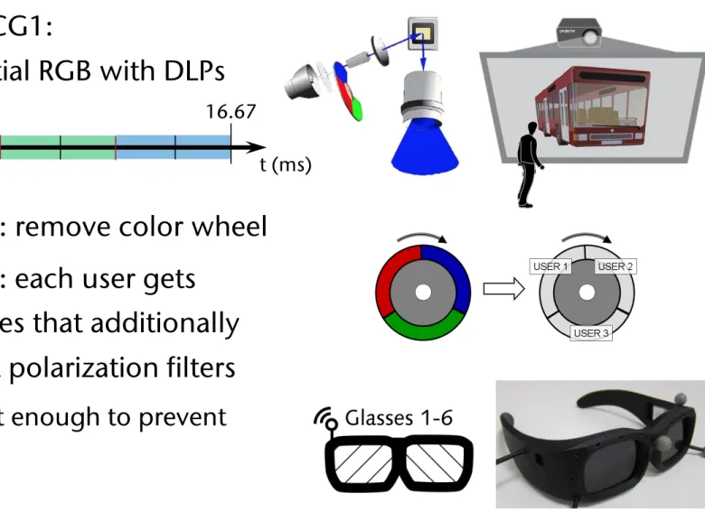
Stereo for 6 Users
[2011]§
Combination of active and passive stereo,plus ingenious utilization of field-sequential projectors
§
Recap from CG1:field-sequential RGB with DLPs
1. Modification: remove color wheel 2. Modification: each user gets
shutter glasses that additionally has left/right polarization filters
§ Must be fast enough to prevent cross-talk!
0 16.67
t (ms)
3D displays. Their systems use modified DLP projectors to project fast time-sequential images onto a rotating anisotropic projection surface. Both systems achieve about one degree of angular resolu- tion and support a 180 and 360 degree field of view, respectively.
[Jones et al. 2009a] reported on a further refined prototype of such a system and showed its use in a very convincing real-time one-to- many teleconferencing application [Jones et al. 2009b]. Due to the use of a single projector, the bandwidth of these systems is limited, which results in a small color depth of one bit color or even only black and white depending on the used DLP projector type. In ad- dition, such a system is difficult to scale to a larger size due to the rotating display surface.
The research surrounding collaborative virtual environments (CVEs) has mostly focused on distributed collaboration (e.g. [Ben- ford et al. 2001] reviews the history of CVEs). [Otto et al. 2006]
and [Wolff et al. 2007] provided a solid analysis of the require- ments for supporting closely coupled collaborative tasks in a shared virtual workspace for non-co-located users, which also apply to a certain extent to co-located collaboration. However, there is lim- ited work on co-located collaboration in projection-based multi- user virtual reality. The original two-user Responsive Workbench work [Agrawala et al. 1997] suggested the use of specialized views, which were used to provide different information to each user, as in a teacher-student scenario. [Riege et al. 2006] suggested the use of a bent pickray to visualize the constraints that are involved when two users are jointly manipulating an object with six degrees of freedom. [d’Angelo et al. 2008] showed that stereoscopic display in combination with collaborative manipulation improve task per- formance and are clearly preferred in a complex assembly task in- volving two users. [Argelaguet et al. 2010] demonstrated the use of specialized views to reduce the problem of interpersonal occlusion.
All these approaches consider only two collaborating users and fo- cus on joint manipulation. It is not clear how these approaches scale to more users.
[Bowman et al. 2005] provide an overview and introduce a taxon- omy for the large variety of navigation techniques for virtual envi- ronments. However, the problem of navigating multiple co-located users with individual views through a shared virtual world has not yet been addressed. Group navigation as it is defined here – mov- ing multiple people simultaneously through a virtual environment – is a new problem that is closely linked to the introduction of stereoscopic multi-viewer systems. Augmented group navigation techniques to mitigate associated issues are orthogonal to general single-user navigation techniques. In our setup each head-tracked person can independently walk in front of the display, but apart from that, does not independently travel within the environment since otherwise the group would no longer share a consistent virtual space.
3 Synchronized 12-View Projector Array
Our goal was to build a fast time-sequential full color DLP-based system which also exploits polarization. Our approach is based on the following ideas:
• Color wheel DLP projectors project the different primary col- ors as fast time-sequential images. There are various color wheel versions; we assume a basic three-segment color wheel consisting of three color filters, one in each primary color:
red, green and blue. If the color wheel is removed, we can
Figure 2:A three-segment color wheel. We display individual im- ages for three eyes instead of time-sequential colors.
• Most DLP projectors rotate the color wheel at least twice per video frame and are thus effectively running at 120Hz while 60Hz input is provided. However, at the time of our devel- opment, a 1920x1200 pixels resolution projector was not yet available, which would accept a 120Hz stereo signal. Thus we had to extend an existing projector to process a 120Hz image stream or to interleave two 60Hz streams. This way we could project six different views at 360Hz (three views times two rotations times 60Hz).
• Polarization can be effectively used in combination with shut- tering to double the number of views, thus allowing 12 views to be achieved using two times three projectors.
Such a system maintains the brightness of a single user active stereo system since we are using six projectors for six users. In addition, we retain full color depth, full resolution (1920x1200) and a 60Hz refresh rate. Figure 3 shows an overview of our setup.
Figure 3:The projector array is driven by a single computer. Three synchronized NVIDIA Quadro Plex 7000 graphics systems are con- nected to the host computer via separate PCIe interfaces. Each Quadro Plex consists of two graphics cards with two DVI outputs each. It produces the left and right eye images for two users. Sets of three DVI outputs carrying the images for three eyes are connected to the video multiplexers (muxer), which rebin the image streams by color and send them to the respective projectors. The left three projectors display the left eye images for the six users, while the right three projectors display the right eye images. The two sets of C1x6: A Stereoscopic Six-User Display for Co-located Collaboration in Shared Virtual Environments • 188:3
sive than standard liquid crystal (LC) shutters and they are very fragile. FLCs are also designed to work with symmetric open/close timings, which is not the case in our setup.
As an alternative to FLCs, we built our shutter glasses based on a novel double-cell shutter design, which consists of two layers of differently configured regular LC shutters. The first layer is a reg- ularly cross-polarized LC shutter (normally white (NW)), which is transparent if no voltage is applied. The second layer has equally oriented polarization filters on both sides and thus it is opaque (nor- mally black (NB)) if no voltage is applied. This combination of shutters functions so that the NB shutter opens quickly while the NW shutter closes quickly. These shutters are ideally suited for an asymmetric use case: our shutters need to be open for only1/360th of a second and closed for5/360thof a second. During the longer closing time, both shutters relax one after the other: first, the NB shutter closes fully and then the NW shutter opens completely (Fig- ure 5). In addition, using a stack of two shutters improves the con- trast ratio, an important property in the context of our system.
Figure 5:Illustration of the double shutter functionality (top), the electrical shutter driving pattern (middle) and the time slots for each user (bottom). At 60Hz a 16.67ms time frame is divided into six adjacent user time slots of equal length. The diagram shows the timings of the double cell shutter of user 4, who receives an image during the fourth slot lasting from T2=8.34ms to T4=11.12ms. The NW shutter is switched off at T1about 2ms before T2to ensure its relaxation and thus maximum light transmission at the beginning of the following opening period. The NB shutter is still blocking light during this NW relaxation phase and immediately opens when the voltage is applied at the beginning of the 4th time slot (T2). At the end of the opening period of 2.78ms (T4) the NW shutter is immedi- ately blocking the light transmission as the voltage is applied. The NB shutter is switched off for relaxation slightly before (T3=11ms).
In a six-user stereo-projection system each individual shutter must blank 11 of 12 displayed images. For a left eye shutter of a particu- lar user three distinct cases can be considered (similarly for a right eye shutter):
Figure 6: Our custom shutter glasses consist of two double cell shutters, a Zigbee radio module, a rechargeable lithium-polymer battery and the shutter driving circuit. The housing also con- tains multiple threaded holes for assembling different IR-reflective marker configurations.
this requirement since the total contrast ratio is the product of the contrast ratios of the NW cell and the NB cell. The third case con- tributes at least one order of magnitude less crosstalk than the other two cases since the light is blocked by shuttering and polarization.
We designed our wireless shutter glasses (Figure 6) such that their principal state can be controlled from the application, independent of the basic clocking. The communication to the shutter glass con- troller is realized by using the µracoli implementation [URACOLI 2011] of the two lower levels of the IEEE 802.15.4 protocol stack for wireless personal area networks (which form the basis of the Zigbee protocol). There are two different aspects that can be pro- grammed:
• The general assignment to one or more of the six-user time slots. This control can be used to implement a VIP (Very Important Person) mode by assigning two or more time slots to a single person. We often have the case that the system is used by less than six individuals and thus we use this control to increase the brightness by assigning more than one time slot to one or more users.
• A transition from shutter mode to full-open mode and vice versa. In regular operation the shutters are open for only 1/6thof the time and thus everything but the display is per- ceived as quite dark. However, if six people are in front of C1x6: A Stereoscopic Six-User Display for Co-located Collaboration in Shared Virtual Environments • 188:5
Optional
The Hardware in Principle
§
6 stereo video streams are generated by 6 graphics cards in 1 PC§
Distribution of the video streams to 6 projectors via multiplexersQuadro Plex GFX Card GFX Card
Quadro Plex GFX Card GFX Card
Quadro Plex GFX Card GFX Card
Gen- lock
Genlock PCIe
Host PC
Muxer
RGB
Muxer
6x red @ RGB 360 Hz
6x red @ 360 Hz
Warning: in the real world, there are no such projectors available!
(capable of 360 Hz inputs)
Optional
§
Timing:§
Demoapplication:
User 1 User 2 User 3 User 4 User 5 User 6
Left Right
360 Hz (Projector)
60 Hz (Renderer)
Previous Work on Co-Located Collaborative VEs
Agrawala et al. 1997 Arthur et al. 1998
Agócs et al. 2006 Kitamura et al. 2001
Optional
Related to Workspace Awareness of CSCW
§
Workspace Awareness = "up-to-the-moment understanding of the other peron's interaction with the shared workspace" [Gutwin &Greenberg, 2002]
§
Factors / questions:§ Who is participating / interacting? (People)
§ What are they doing ? What will they be doing next? (Actions / Intentions)
§ What can they see? Where can they have effects? (Perception / Influence)
Optional
An Interaction Issue with Correct Multi-User-Pojection
§
Navigation: the "navigator"controls the path for all users (and he sees only his own viewpoint!)
§
Problem: the other users'viewpoint goes through walls
§
Solution:§ Adjust the paths of the other users automatically to bring them closer to the navigator's viewpoint
§ Fade away obstacles in the path of each user
Optional
Automultiscopic Display
§
Like a lightfield / holographic display, but views/images differ only along horizontal viewpoint changes§
Special screen sends images from projectors only in one direction with a very small scattering angle (1o)216 projectors
Screen = anisotropic light shaping diffuser;
scatters light vertically, maintains narrow horizontal blur
1o degree horizontal blur
Challenges
§
If number of cameras < number of projectors ⟶video streams for "in-between" projectors must be interpolated from neighboring streams
§
Bandwidth: 1920 x 1080 x 24 bits x 60 FPS x 216 cams = 80 GB/sec§
Synchronization between all GPUs (swapbuffers) and all projectors (VSYNC)§
Lenticular screen with small horizontal diffusion angle:§ From a specific viewing direction, the light from a single projector appears as a single stripe of light
§
Advantage: unlimited number of viewers§
Disadvantages:§ Expensive (lots of projectors), and needs lots of space
§ Does not work with tilted heads (eyes must be aligned with the lenticular lenses)
Rendering on HMDs
§
Optics in HMDs usually cause some amount of distortion§ Especially the Oculus Rift
§
Idea: pre-distortion (using multi-passand texturing or shaders)
HMD lens distortion
Pre-distortion (e.g., by shader)
Displayed image
HMD lens Distortion Computer
monitor
(after distortion HMD by its lenses)
One of the Hard Requirements for VR / AR
§
Images must appear fixed in space, no matter how users moveOptional
Recap: the Graphics Backend Hardware
§
Current displays are always raster displays:§
Double buffering to prevent flickering (i.e., a race condition):§ Best point to swap the buffers?
⟶ VSYNC
Horizonal backtrace (HSYNC) Scanline
Vertical backtrace (VSYNC)
Graphics Pipeline
Z buffer
swap buffers
Front buffer Back buffer