Synthesis and Characterization of U(VI)-Complexes with Organic Ligands by Spectroscopy and Quantum Chemical
Methods
Master Thesis
Technische Universität Dresden
Fakultät Mathematik und Naturwissenschaften Fachrichtung Chemie und Lebensmittelchemie
Professur für Radiochemie/Radioökologie
by
Ilka Vinçon
born
02/08/1992 in Rottweil
Supervisor: Prof. Dr. Thorsten Stumpf
Supervisor: Dr. Michael Patzschke
Dresden, 14/06/2018
Credits
Thanks to everyone who supported and motivated me during the preparation of this thesis!
First of all, I would like to thank Prof. Dr. Thorsten Stumpf for offering me the possibility to do interesting research during the past six months. Thanks a lot to the department off-element chemistry and Atsushi Ikeda-Ohno for the warm welcome in the group.
Above all, cordial thanks to Michael Patzschke and Juliane März for their indispensable sup- port and the many, many helpful discussions! Michael equipped me with all necessary knowl- edge to run calculations and to partly become a computational chemist. Juliane introduced me to every single device and working technique, and only thanks to her patience and con- stant day-to-day support in the laboratory I could finally manage all experimental work. In this regard, also many thanks to Sebastian Schöne, who introduced me to the world of single crystal diffraction and was always available for any kind of question.
Special thanks to Peter Kaden for NMR measurements, Karsten Heim for IR solution spectra and Robin Steudtner for the introduction to LIFS and support with the measurements.
Last but not least, I would like to thank all my colleagues, friends and family for the moral support, cookies and coffee while I prepared this thesis.
II
Contents
List of Figures . . . IV List of Tables . . . V List of Abbreviations . . . VI
1 Motivation . . . 1
2 Complex Formation of U(VI) withN-Donor Ligands . . . 3
2.1 Properties of Uranium . . . 3
2.2 N-Donor Ligands . . . 4
2.3 Uranium(VI) Complexes of 2,2’-Bipyridine and 1,10-Phenanthroline . . . 6
2.4 Complex Formation from Non-Aquatic Media . . . 8
3 Theoretical Concepts . . . 9
3.1 Density Functional Theory . . . 9
3.2 Solvent and Dispersion Interactions . . . 13
3.3 Charges and QTAIM-Analysis . . . 14
4 Results . . . 17
4.1 Synthesis and Characterization of Uranium Bipyridine Complexes . . . 17
4.1.1 Synthesis . . . 17
4.1.2 Characterization of [UO2Cl2(Bipy)(H2O)] . . . 18
4.1.3 Characterization of [UO2Cl2(Bipy)(Sol)] . . . 19
4.1.4 Molecular Packing of [UO2Cl2(Bipy)(Sol)] . . . 21
4.1.5 Characterization of Crystals formed in Acetonitrile . . . 24
4.2 Thermodynamic Stability of [UO2Cl2(Bipy)(Sol)]-Complexes . . . 26
4.2.1 Structural Representation and Crystal Packing Effects . . . 26
4.2.2 Model of Complex Formation in Acetone . . . 29
4.2.3 Order of Thermodynamic Stability . . . 32
4.2.4 Electronic Stabilization within the Complexes . . . 35
4.2.5 Stability of the Solvent-Uranium Bond . . . 38
4.2.6 Model of Complex Formation in Protic Solvents . . . 40
4.2.7 Reaction Energies for Formation from Protic and Aprotic Solvents . . . 41
Contents III
4.3 Complex Stability in Solution . . . 42
4.3.1 Determination of pH of Complex Solutions . . . 42
4.3.2 Investigation by NMR-Spectroscopy . . . 42
4.3.3 Investigation by IR Spectroscopy . . . 45
4.3.4 UV-Vis Absorption Spectroscopy for variable M:L ratio . . . 46
4.3.5 Fluorescence Spectroscopy for variable M:L ratio . . . 48
4.3.6 Conclusion . . . 49
4.4 Stabilization of Uranium(VI)-Pyridyl-Complexes in the Solid-State . . . 50
4.4.1 π· · ·πInteractions in the Solid State Structure of [UO2Cl2(Bipy)(EtOH)] 50 4.4.2 Synthesis and Characterization of Uranium Phenanthroline Complexes 52 4.4.3 QTAIM-Analyse of [UO2Cl2(Bipy)2] versus [UO2Cl2(Phen)2] . . . 53
4.4.4 Solid State Stabilization in Phenanthroline-Complexes . . . 54
5 Conclusion and Outlook . . . 56
6 Experimental Part . . . 58
6.1 Synthesis . . . 58
6.1.1 Synthesis of UO2Cl2·H2O . . . 58
6.1.2 Synthesis of [UO2Cl2(Bipy)(H2O)] . . . 58
6.1.3 Synthesis of [UO2Cl2(Bipy)(Sol)] . . . 59
6.2 Measurements . . . 59
6.2.1 Powder X-Ray Diffraction . . . 59
6.2.2 Single Crystal X-Ray Diffraction . . . 59
6.2.3 Elemental Analysis . . . 60
6.2.4 Nuclear Magnetic Resonance Spectroscopy . . . 60
6.2.5 UV-Vis Absorption Spectroscopy . . . 60
6.2.6 IR Spectroscopy . . . 60
6.2.7 Laser-Induced Fluorescence Spectroscopy . . . 61
6.3 Calculations . . . 62
6.3.1 Calculations with Turbomole . . . 62
6.3.2 Calculations with ORCA . . . 63
6.3.3 QTAIM Analysis with Multiwfn . . . 63
References . . . 64
A Appendix . . . 72
A.1 Determination of Rotation Velocity of Solvent Molecule . . . 72
A.2 Synthesis of UO2Cl2·H2O . . . 73
A.3 Elemental Analysis for [UO2Cl2(Bipy)(H2O)] . . . 73
A.4 Direct Synthesis of [UO2Cl2(Bipy)(EtOH)] . . . 74
A.5 Characterization of Uranium(VI)-Phenanthroline System . . . 76
IV
List of Figures
Figure 1.1: Ligand-Uranium system under investigation . . . 2
Figure 2.1: Uranium minerals and their crystal structure . . . 3
Figure 2.2: Overview ofN-donor ligands . . . 5
Figure 2.3: Selected U(VI)-bipyridine and phenanthroline complexes . . . 8
Figure 3.1: Jacobs Ladder . . . 11
Figure 3.2: Concept of QTAIM-Analysis . . . 16
Figure 4.1: Characterization of [UO2Cl2(Bipy)(H2O)] . . . 18
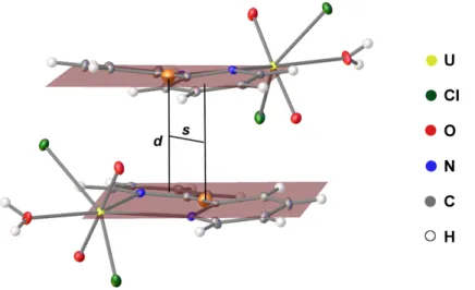
Figure 4.2: Definition of molecular stacking . . . 23
Figure 4.3: Characterization of U(VI)-complexes from acetonitrile . . . 25
Figure 4.4: Complexes [UO2Cl2(Bipy)(MeCN)] and [UO2Cl2(Bipy)2] . . . 26
Figure 4.5: Structural variation during theoretical simulation . . . 27
Figure 4.6: Structural of [UO2Cl2(Bipy)(Me2CO)] by theory and experiment . . . 28
Figure 4.7: Potential scan for a rotation of acetone within UO2Cl2(Bipy)(Me2CO) . . . 29
Figure 4.8: Model solution species of UO2Cl2. . . 30
Figure 4.9: Potential scan for 2,2’-bipyridine along the dihedral angle N−C−C−N . . 34
Figure 4.10: NBO-Charge-Analysis for bipyridine uranium complexes. . . 35
Figure 4.11: DIs for interactions within bipyridine uranium complexes . . . 37
Figure 4.12: Potential scan for a solvent and ligand displacement . . . 39
Figure 4.13: Assignment of 1H-NMR shifts of 2,2’-bipyridine . . . 43
Figure 4.14: pH-dependence of 1H-NMR shifts . . . 44
Figure 4.15: IR spectra in solution . . . 45
Figure 4.16: UV-Vis absorption spectroscopy for solutions with variable M:L ratio . . . 47
Figure 4.17: Fluorescence spectroscopy for solutions with variable M:L ratio . . . 48
Figure 4.18: Segment of [UO2Cl2(Bipy)(EtOH)]-structure forπ· · ·πanalysis . . . 51
Figure 4.19: Characterization of uranium-phenanthroline via P-XRD . . . 52
Figure 4.20: Structural comparison for [UO2Cl2(L)2]. . . 54
Figure A.1: Characterization of the synthesis product UO2Cl2·H2O. . . 73
Figure A.2: Characterization of [UO2Cl2(Bipy)(EtOH)] . . . 74
Figure A.3: Characterization of uranium-phenanthroline via IR . . . 76
V
List of Tables
Table 2.1: Overview of uranium(VI) bipyridine complexes . . . 7
Table 4.1: Molecular structures and parameters of [UO2Cl2(Bipy)(Sol)]-complexes . . 20
Table 4.2: Crystal structures of [UO2Cl2(Bipy)(Sol)]-complexes . . . 22
Table 4.3: Accuracy of calculations . . . 32
Table 4.4: Formation of [UO2Cl2(Bipy)(Sol)] in aprotic solvents . . . 32
Table 4.5: Thermodynamic parameters for the solvent exchange reaction . . . 33
Table 4.6: QTAIM analysis for bipyridine uranium complexes. . . 37
Table 4.7: Potential scan for a solvent and ligand displacement . . . 39
Table 4.8: Reaction energies in protic and aprotic solvents . . . 41
Table 4.9: 1H-NMR shifts for 2,2’-bipyridine in ethanol. . . 43
Table 4.10: 1H-NMR shifts for 2,2’-bipyridine at variable pH. . . 44
Table 4.11: Fluorescence spectroscopy for solutions with variable M:L ratio . . . 48
Table 4.12: Energetic survey for interactions within [UO2Cl2(Bipy)(EtOH)]. . . 50
Table 4.13: Formation of U-Phen complexes in aprotic and protic solvents . . . 53
Table 4.14: QTAIM analysis for [UO2Cl2(L)2]. . . 54
Table A.1: Elemental analysis of [UO2Cl2(Bipy)(H2O)] . . . 73
Table A.2: Crystal structure data of various compounds . . . 75
Table A.3: Elemental analysis of [UO2Cl2(Phen)2] and [UO2Cl2(Phen)(H2O)] . . . 76
VI
List of Abbreviations
(FT)IR (Fourier Transform) Infrared ATR attenuated total reflection
B3LYP Becke 3-term functional with Lee, Yang, Parr exchange
Bipy 2,2’-bipyridine
BP Becke, Perdew
BSSE basis set superposition error COSMO conductor-like screening model
CSD Cambridge Structural Database
d doublet (NMR)
DFT density functional theory
DLPNO-CCSD(T) coupled cluster method with singe and double excitation and perturba- tive triple excitation using domain based local pair natural orbital
e.g. exempli gratia (for example)
EA elemental analysis
ECP effective core potential et al. et alii (and others)
EtOH ethanol
HF Hartree-Fock
HSQC heteronuclear single quantum correlation
VII
i.e. id est (that is)
KS Kohn-Sham
L ligand
LCAO linear combination of atomic orbitals LIFS Laser Induced Fluorescence Spectroscopy
m multiplet (NMR)
Me methyl-
MeCN acetonitrile
NBO natural bonding orbital
NMR Nuclear Magnetic Resonance
OTf triflate/trifluoromethanesulfonate P-XRD Powder X-Ray Diffraction
PBE Perdew–Burke-Ernzerhof
Phen 1,10-phenanthroline
QTAIM quantum theory of atoms in molecules
SARC segmented all electron relativistically contracted basis sets SC-XRD Single Crystal X-Ray Diffraction
Sol solvent
SV(P) split valence basis set with one polarization function
t triplet (NMR)
THF tetrahydrofurane
TZVPP triple zeta valence basis set with two polarization functions
VIII UV-Vis Ultra Violet and Visible range of electromagnetic spectrum
ZORA zeroth order regular approximation
1
1 Motivation
Actinides are fascinating elements - situated at the very bottom of the periodic table, they are the heaviest elements accessible in ponderable quantities so far and a variety of peculiar effects arise from their large mass. Not only are they radioactive and thus mostly identified only within the last century by artificial production, but also the first elements discovered to undergo nuclear fission. As such, uranium, which is found in sufficient quantity in nature, is vastly exploited as a fissile material in nuclear fuel industry.1,2
The widespread technical application spurred interest in the chemistry of these elements.
Development of strategies for fuel reprocessing or secure radioactive waste storage benefit from a proper understanding of the chemical behavior and the interaction with the environ- ment.3–5Thus, the general bonding behavior, stability and coordination chemistry have been subject to intense research in the past decades.6–8
These fundamental investigations on the basis of model systems such as complexation with relevant ligands revealed most interesting properties. First of all, they exhibit a rich redox chemistry with a variety of oxidation states accessible for middle actinides like plutonium or neptunium. Additionally, actinides demonstrate a peculiar covalent behavior which may be caused by a participation of f-electrons in bonding. Both features could be eventually ex- plained by the non-negligible relativistic effects due to their large atomic mass.1,2
As a predominant oxidation state of uranium, the complexation of uranium(VI) has been in- vestigated with a variety of ligands, first in aqueous solutions9,10 followed by non-aqueous investigations to avoid oxygen and water as donors.11,12 Amongst them, the multidentate pyridyl basedN-donors have attracted attention due to their prospective usage in separation of trivalent lanthanides and actinides6,13and a many-faceted complexation behavior has been demonstrated also for U(VI) by these ligands.
Only recently, complexation of uranyl(VI) with the simplest bidentate pyridyl ligands 2,2’- bipyridine (Bipy) and 1,10-phenanthroline (Phen) by S. Schöne et al. revealed the formation of [UO2Cl2Phen2] with an extraordinary geometry in solid state, while an analogous com- plex was not found for the very similar 2,2’-bipyridine ligand.14Furthermore, although pyridyl- uranium(VI) systems have been broadly investigated in the solid state judging the numerous entries in the Cambridge Structural Database (CSD) ,15 no solution species seems to be known so far.
Thus, it would be very interesting to detect the key aspects of the stability of these com- pounds. It would be enlightening to identify the driving force of their formation, how they exist in solution and if the solvent influences their formation. This might eventually allow to
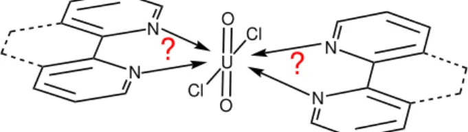
1 Motivation 2 conclude also on the reactivity of bipyridine versus phenanthroline. The motive of this thesis was to tackle these questions by a revised investigation of the bipyridine-uranium(VI) and phenanthroline-uranium(VI) system (see sketch Figure 1.1).
U O
O Cl
Cl
N
N
? ?
N N
Figure 1.1:Sketch of the ligand-uranium(VI) system investigated within the scope of this thesis.
Complexes shall be synthesized using different non-aqueous solvents, as this seemed to be the key for the formation of novel structures in recent studies.11,12,16 These uranyl(VI)-ligand complexes shall then be analyzed in the solid state by SC-XRD, P-XRD and IR spectroscopy.
Solution investigations applying various methods including NMR, UV-Vis, LIFS and IR spec- troscopy shall allow to determine the presence of potentially stable solution species. The experiments will be complemented by an extensive theoretical survey. The aim is to classify thermodynamic properties of formation for different solvent systems, analyze the complexes’
electronic properties and determine their solid-state properties. Finally, the reasons for the reactivity differences between 2,2’-bipyridine and 1,10-phenanthroline shall been identified by this combined experimental and theoretical investigation.
3
2 Complex Formation of U(VI) with N -Donor Ligands
2.1 Properties of Uranium
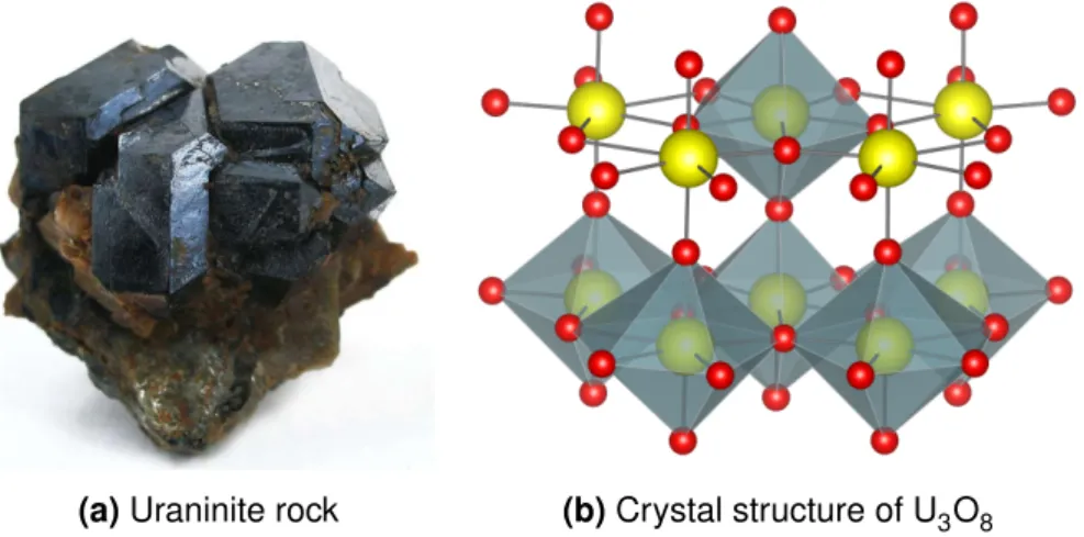
Uranium is one of the heaviest elements in nature,2 named after a planet11and has already been used by the romans for coloring glasses12 – discovered in 1789 by Klaproth,1,11 it is today one of the most frequently applied radioactive elements. An α emitter on its own,11 uranium (235U) is able to undergo fission which led to its exploitation for technical applica- tions in the nuclear fuel industry and for weapons production.1,2 As such, there is also an increased interest in this element from a chemist’s point of view: In order to enable long term radioactive waste storage, the possible interactions of actinides with its surrounding need to be determined.2Uranium is often used in these studies instead of heavier actinides due to its lower radioactive hazard6 and the readily available raw material, since it is widely distributed in the earth crust in form of its oxides uraninite and pitchblende (see Figure 2.1).1,2Moreover, chemical peculiarities evolving for actinides due to the non-negligible relativistic effects for heavy elements arouse the interest in determining their fundamental chemistry with intense research carried out for uranium during the past decades.11
(a)Uraninite rock (b)Crystal structure of U3O8
Figure 2.1:Naturally occurring uranium mineral (a) and the crystal structure of the common oxide U3O8(b) with the pentagonal bipyramidal coordination containing the uranyl unit.17,18
Several relativistic effects have been identified for the actinides and a multitude of macro- scopic properties could be ascribed to them. Firstly, the relativistic mass increase leads to a direct relativistic orbital contraction for s and p orbitals. As a consequence, the nucleus is shielded and d and f orbitals are prone to an indirect relativistic orbital expansion. They are thus more available for bonding and give rise to a significant covalency.2,11The increased
2.2 N-Donor Ligands 4 availability of f-electrons also facilitates oxidation and a broader range of oxidation states similar to transition metals and unlike the 4f-elements are observed for the early actinides.
For uranium, oxidation states between II and VI are accessible with IV and VI being the most stable.1,11Moreover, the close proximity of 5fand 6d orbitals in uranium allows a hybridization of these orbitals. As another relativistic effect, spin-orbit coupling is now profound and com- petes with inter-electronic repulsion. Thus, Russel-Saunders coupling is not ideally fulfilled anymore, which explains the observation of more difficult electronic absorption spectra.2,11 Within structural uranium chemistry, the outstanding relativistic effect is the formation of the very stable uranyl unit UO22+ for U(VI) compounds. This linear O−U−O moiety is already present within the structure of U3O8 and its unusual stability is the key factor for nuclear fuel reprocessing techniques. Intense studies during the past century revealed the bonding behavior and crystal chemistry of uranium (VI) compounds.2,12,19 The typical trans arrange- ment of the uranyl unit is ascribed to a participation of f-orbitals in the bonding.1,2 A very strong, multiple covalent bond is formed, which possesses a formal bond order of 31,2,12 and an approximate U−O bond length of 1.79 Å essentially independent of the presence of other ligands within the coordination sphere.19 This characteristic bond can be used as an experimental indicator, since the asymmetrical stretching vibration appears at about 920 to 980 cm−1 in IR spectra1and is weakened by the presence of other ligands.12
With the strict trans arrangement of the uranyl entity, coordination of other ligands is limited to the equatorial plane.12,19 Only one molecular orbital is available to interact, thus usually only weak electrostatic interactions are formed.11,12 However, complexes are readily formed with oxygen donors,20 e.g. nitrates and phosphates are applied for nuclear waste reprocess- ing, carbonate complexes are formed during extraction of uranium from ores and in solution, water or other solvents are coordinated to uranium.1Common geometries are an octahedral, pentagonal bipyramidal or hexagonal bipyramidal coordination environment by an attachment of 4,5 or 6 ligands in the equatorial plane, respectively . While the hexagonal arrangement is found for bidentate ligands, the pentagonal coordination is the most common geometry and can also be found in the naturally occurring ore1,19 (see Figure 2.1).
2.2 N-Donor Ligands
N-donor ligands are widely applied within the coordination chemistry of uranium.7 Interest has been spurred by the fact that the linear uranyl unit demonstrated a preference for soft donors like N during a selective complexation with bifunctional ligands possessing both, a Schiff base and a crown ether, as donor functions.21 Discovery of compounds with catalytic or sensoric activity,6 the importance of N-donor ligands within biological systems8 and their suitability as extraction agents for radioactive waste reprocessing6 further promoted research
2.2 N-Donor Ligands 5 in this area, including the synthesis of new uranium complexes. This steady expansion by further U-N compounds also opens up new ways for a detailed investigation and fundamental understanding of the complicated bonding behavior of uranium.6
N N
OH HO
HN N HN N NH
NH
N N N
N
N Si
Si Si N
N Si salophen
isoamethyrin
2,2':6',2'':6'',2'''-quaterpyridine
amide amidinate
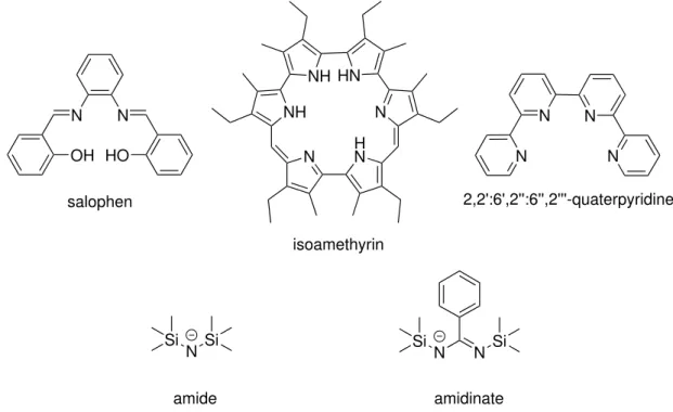
Figure 2.2:Selection of commonN-donor ligands for a complexation of U(VI).
A variety of U(VI)-N-complexes could be characterized thus far. Apart from few exceptions, all complexes contain the linear UO22+-unit. A selection of possibleN-donor ligands is shown in Figure 2.2. Anionic ligands include amides, amidinates and cyanates, but uranium com- plexes are also formed with neutral N-donors like amines, N-heterocycles or salophenes as mixedN,O-functional Schiff bases.7 Some uranium-ligand systems have demonstrated spe- cific characteristics, e.g. a catalytic activity for thiol addition could be detected for tetradentate salophen uranyl complexes, while pyrrol ligands like isomethyrin can be applied as uranyl sen- sors due to their color change during reductive complexation.6Ligands containing the pyridine unit – already known for its selective metal coordination in various other branches of chem- istry – on the other hand are suited for a separation of trivalent actinides from lanthanides by extraction and are thus of specific importance. This selectivity arises from the more covalent bond character for actinides than for lanthanides.6,13Due to the basicity of polypyridyl ligands like 2,2’:6’,2”:6”,2”’-quaterpyridine, shorter metal-N-bonds are formed for actinides which are additionally within the area of optimal bond length for minimal steric strain.13
The strength of a pyridyl ligand can be further increased with the number ofN-donor groups based on the chelate effect and using preorganization effects in a rigid ligand obtained by an addition of benzo groups to its backbone. Hydrogen bonding interactions in the backbone on the other hand, which are present for example in 2,2’-bipyridine in its complex forming
2.3 Uranium(VI) Complexes of 2,2’-Bipyridine and 1,10-Phenanthroline 6 cis-conformation, cause a destabilization of the complex and lead to twist. Within solids, π- interactions serve as stabilization with a typicalπ· · ·πdistance of 3.4 Å.13
The simplest polypyridyl ligands are 2,2’-bipyridine and 1,10-phenanthroline, which have been used as ligands within this work. Thus, the following section is devoted to giving an overview on compounds of this metal-ligand system investigated so far.
2.3 Uranium(VI) Complexes of 2,2’-Bipyridine and 1,10-Phenanthroline
A broad spectrum of uranyl complexes with 2,2’-bipyridine (Bipy) or 1,10-phenanthroline (Phen) as the organic ligand have been synthesized up to now and their structures have been determined by crystallization. Overall, more than 40 different compounds which contain a [UO2(Bipy)]2+-unit and even more with a [UO2(Phen)]2+-unit have been added to the Cam- bridge Structural Database (CSD) to date.15 The listed compounds can be classified as mononuclear complexes, networks and hydroxo-, oxo- or azido-bridged multinuclear com- plexes. An overview of mononuclear complexes of the uranium-bipyridine system published within the CSD is given in Table 2.1, while an analogous register for phenanthroline com- plexes has already been aquired by S. Schöne et al. .14
Apart from the sole known 1:2 complex,16,32 all bipyridine complexes are characterized by a bipyramidal geometry, a linar, axial O−U−O-unit with an U−O distance of 1.75 to 1.78 Å and the equatorial positioning of the bipyridine ligand located at a distance of 2.45 to 2.67 Å from the uranium.
The majority of these complexes have been obtained at hydrothermal conditions using halo- gen-substituted benzoic acids as the anion.23,25–27,33Coordination by bipyridine and two biden- tate benzoic acid derivates in a plane perpendicular to the uranyl unit leads to a hexagonal bipyramidal coordination sphere (Figure 2.3a) for uranium with a distortion of the bipyridine from the equatorial plane depending on the anions’ steric demand. Current interest in these hybrid materials arises from their potential application in nuclear waste reprocessing20and as nuclear fuel.23 The multidimensional structure is formed by a supermolecular assembly: the pyridyl unit serves as a capping agent while chains, twodimensional layers and threedimen- sional structures are obtained for bipyridine and phenanthroline complexes due to π· · ·π,23 H· · ·O,25,26 X· · ·O,27and X· · ·X27interactions (X = halogen) with an increasing contribution ofπ· · ·πinteractions for the phenanthroline complexes.26Due to partial hydrolysis, dinuclear complexes and networks25are formed besides the mononuclear complexes during aqueous synthesis in dependence of the pH.26
Alternative synthesis routes from non-aqueous media enabled the targeted production of only mononuclear bipyridine16,31 and phenanthroline14,16 complexes including the formation of novel geometries together with a coordination by more than one pyridyl ligand (see Fig-
2.3 Uranium(VI) Complexes of 2,2’-Bipyridine and 1,10-Phenanthroline 7 Table 2.1:Overview of uranium(VI) bipyridine complexes published with their crystal structure in
the CSD. Basic parameters and their geometry are given.
complex O−U−O
in∘
U−O in nm
U−N in nm
coordination geometry
ref.
[UO2(NO3)2(Bipy)] 177.8 1.763 2.578 hexagonal-b. [22]
[UO2(CH3COO)2(Bipy)] 178.3 1.775 2.631 hexagonal-b. [22]
[UO2(C6H6COO)2(Bipy)] 179.6 1.766 2.667 hexagonal-b. [23]
[UO2(C6F5COO)2(Bipy)] 172.1 1.635 2.475 hexagonal-b. [24]
[UO2(C6Cl2H3COO)2(Bipy)] 179.6 1.775 2.658 hexagonal-b. [25]
[UO2(C6Br2H3COO)2(Bipy)] 179.4 1.761 2.665 hexagonal-b. [25]
[UO2(C6I2H3COO)2(Bipy)] 178.7 1.759 2.633 hexagonal-b. [26]
[UO2(C6Cl2H3COO)2(Bipy)] 178.5 1.771 2.641 hexagonal-b. [27]
[UO2(C6Br2H3COO)2(Bipy)] 179.0 1.761 2.633 hexagonal-b. [27]
[UO2(C6Cl3H2COO)2(Bipy)] 179.2 1.753 2.598 hexagonal-b. [28]
[UO2(C10N2H7COO)2(Bipy)] 179.0 1.753 2.606 hexagonal-b. [29]
[UO2(Van−L−His)(Bipy)]* 174.8 1.761 2.555 pentagonal-b. [30]
[UO2(N3)(Bipy)](Ph−PPh3) 177.4 1.779 2.619 pentagonal-b. [31]
[UO2(OTf)2(Bipy)] 180.0 1.754 2.605 rhomboedric [16]
* N-o-vanillylidene-L-histidinate
ure 2.3). Rhomboedric complexes [UO2(OTf)2(Bipy)2] and [UO2(Phen)3](OTf)2have been ob- tained from mixtures of the ligand with UO2(OTf)2 in acetonitrile by Berthet et al..32 In these complexes, the equatorial arrangement of the ligands is heavily distorted and the sum of the angles between uranium and the donor atoms deviates by more than 30∘from the ideal value of 360∘.16For bipyridine, [UO2(OTf)2(Bipy)2] is the only known uranyl complex with a metal to ligand ratio deviating from 1:1.15 The application of a weakly bound counter ion (triflate) and acetonitrile as a non interacting solvent are assumed to be the cause of this unique forma- tion.16Several further attempts to alter the stoichiometry of the uranium-bipyridine complexes using N3– and acetonitrile,31Cl– and a H2O/acetone mixture14or OTf– in THF and pyridine16 as the counter ion and solvent, respectively, failed, which seems to confirm the hypothesis.
Phenanthroline complexes of the uranyl cation with more than one ligand are also rare. Apart from the aforementioned salt like 1:3 complex [UO2(Phen)3](OTf)2,16a 1:2 complex could be crystallized from a mixture of UO2Cl2and Phen in acetone by Schöne et al. for the first time.14 With a dodecahedral ligand arrangement plus a non-linear O−U−O unit (161.8∘),14this com- plex combines several novel structural features at once. Recently, Carter et al. demonstrated that such a 1:2 complex can also be formed with carboxylate as the anion under aqueous conditions if an appropriate synthesis is chosen.28
2.4 Complex Formation from Non-Aquatic Media 8
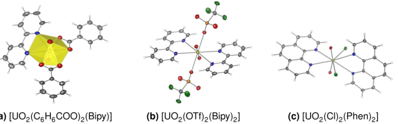
(a)[UO2(C6H6COO)2(Bipy)] (b)[UO2(OTf)2(Bipy)2] (c)[UO2(Cl)2(Phen)2]
Figure 2.3:Selected bipyridine and phenanthroline complexes of U(VI). A typical uranium bipyridine complex with its hexagonal coordination sphere is shown in (a). Multiple coordination of bipyridine (b) or phenantrholine (c) allows the formation of special coordination ge- ometries. Anisotropic displacement ellipsoides are drawn with 50 % probability. Color code: U - yellow, O - red, N - blue, C - grey, H - white, Cl/F - green, S - orange.
2.4 Complex Formation from Non-Aquatic Media
With the environmental fate of uranium being of the utmost importance for a geological depository and due to its presence in nature,9,10 the speciation of uranium and its com- plexes in aqueous solution has been extensively investigated within the past decades.9,10 Recently though, investigations in non-aquatic media have received considerable attention due to their significance for gaining fundamental unterstanding of the bonding behavior of 5f-elements.11,12
The application of novel ligands – previously per se excluded from usage e.g. due to their insolubility in aqueous media34 – is feasible under non-aqueous conditions and allows the formation of complexes with structures beyond the thermodynamic stability of aqueous sys- tems.11 For example, a stable U(V)-compound could be obtained, which is prone to rapid disproportionation forming U(IV) and U(VI) compounds under aqueous conditions.12 With an increase in the variety of complexes and structures, new theoretical models can be tested and fundamental principles like the bonding behavior of uranium, its covalency or the as- pects of its reactivity can be determined.11,34 Furthermore, such investigations might provide new insights into the electronic structure, which – e.g. in terms of magnetism – is not yet completely understood.11 Finally, the performance of actinides in non-aqueous media might be an important application for a liquid-liquid extraction in future scenarios of nuclear fuel reprocessing.7,35
9
3 Theoretical Concepts
3.1 Density Functional Theory
A main goal of theoretical chemistry is an accurate prediction of molecular structures and de- scription of the electronic energy of a system.36 Although sophisticated wave-function based methods like couple cluster methods (e.g. DLPNO-CCSD(T) ) offer a very accurate descrip- tion of even difficult systems, these methods are often computationaly too demanding for larger systems. With a rapid development of density functional theory (DFT) in the 1960s, a faster and yet robust method has been found and DFT has become by now the most widely used method of electronic structure calculation.37,38
The intriguing property of density functional theory is the complete restriction to the electron densityρ(r), which depends only on three spatial variables and can be directly experimentally obtained from X-Ray diffraction, while all other molecular properties including the electronic energyE are received as a functional of this electron density38
E =E[ρ(r)]. (3.1)
Wave function based methods on the contrary require the treatment within a 4N dimensional space. The idea for the expression in 3.1 has been originally published by Thomas and Fermi back in 1927.39,40However, an adequate model of the functional which allowed to yield meaningful results was long missing and only given by the developments of Hohenberg, Kohn and Sham in the 1960s.38
Hohenberg and Kohn established and proofed an unambiguous assignment between electron density and energy based on two theorems: Their first theorem proofed that the ground state and thus molecular properties can indeed be unambiguously assigned as a functional of the electron density. The second theorem rationalized the application of the variational principle by proving that the energyE[ρ] for an arbitrary electron densityρis always an upper bound to the ground state energyE0[ρ0] connected to the ground state electron densityρ0.36,38 Based on these theorems, Kohn and Sham developed a method to obtain a good estimation of the ground state energy by a meaningful construction of the energy functional:38,41
E[ρ] =T[ρ] +J[ρ] +ENe[ρ] +Exc[ρ]. (3.2)
3.1 Density Functional Theory 10 Here, the energy functional E[ρ] is separated into the kinetic energy functional (T[ρ]), the classical electron-electron interaction (J[ρ]), the nuclei-electron attraction (ENe[ρ]) and an ex- change and correlation functional (Exc[ρ]). The main contribution of Kohn and Sham was a clever description of the kinetic energy functional (T[ρ]) via a substitute system of non- interacting electrons, whose electron density ρs equals exactly that (ρ) of the "true" sys- tem.38,41 An exact solution for the non-interacting system is feasible via a Hartree-Fock (HF) like approach as a single slater-determinant of a set of Kohn-Sham (KS) orbitals φi, which reduced the problem to the Kohn-Sham equations36
[︂
−1 2∇2+
∫︁ ρ(r′)
|r−r′|dr′+Vxc(r) +VNe(r) ]︂
φi =iφi. (3.3) Although the introduction of orbitals again increases the computational cost, the construction of a set of single particle equations allows a straight forward solution yielding the optimized KS-orbitals for a given basis set, which can be used to calculate the electron density38
ρ(r) =∑︁
i
|φi|2. (3.4)
KS-orbitals are usually described by the LCAO-ansatz . Each orbital is a linear expansion of predefined basis functions, whose choice is essential for a good representation.38 Generally, the quality of the basis sets can be increased by choosing a larger expansion.36
The equations developed so far would allow an approximation-free description, if the ex- change and correlation term Exc[ρ] was known. Exc[ρ] contains the non-classical treatment of the electron-electron interactions, the correction of self-interaction and the correction to the non-interacting kinetic energy. Since an analytical description is not known, DFT comes down to accurately guessing this functionalExc[ρ].38
Exchange and Correlation Functional
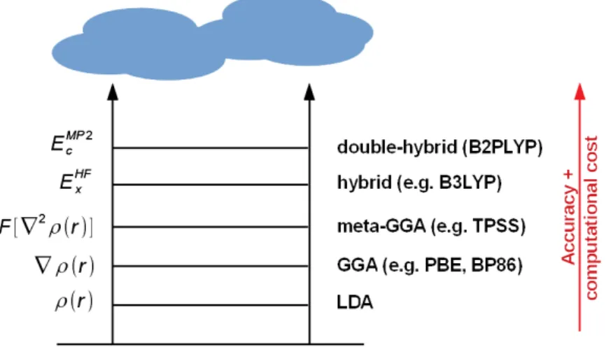
Unfortunately, there is no systematic way to improve functionals and the quality of a DFT approach can only be validated by a comparison with wave-function methods. Nevertheless, more and more sophisticated methods have been developed which at the same pace be- come more complex and computationally expensive.38,41 This has been nicely outlined in the methaphorical picture of a Jacobs ladder by Perdew et al.42(see Figure 3.1).
Firstly, functionals were improved by an increasingly accurate description of the spatial prop- erties of the electron density. The first functionals only considered densities via the uniform electron gas model (LDA = local density approach). Due to this simplification, they failed to reproduce rapidly changing densities in molecules38and predicted too large binding energies and too short bond lengths.41 An incorporation of the spatial variation via the gradient ∇ρ
3.1 Density Functional Theory 11
Figure 3.1:Exchange and correlation functionals for DFT within the framework of the Jacobs ladder.
(GGA = generalized gradient approach) for functionals like PBE or BP86 was able to resolve this problem, but meaningful values for atomisation energies and barrier heights were only achieved when delocalization of electrons within the molecule was partly considered by in- clusion of second derivative information (meta-GGA, e.g. TPSS).38,41
Some main problems of DFT calculations – missing treatment of long-range dynamic correla- tion and strong correlation, and the self-interaction error, – could however not be tracked via the previous route.41 Since at least the latter is correctly described by the HF theory, a new generation of functionals was constructed by a partial substitution ofE[ρ(r)] by wave-function calculated terms. Both, hybrid and the recently developed double hybrid functionals belong to this category.38For hybrid functionals like the popular B3LYP or PBE0, the exchange part is partly substituted by a Hartree-Fock calculated term41
Exc = (1−0.20)ExDFT+ 0.20ExHF+EcDFT. (3.5) For a double hybrid functional, additionally a part of the correlation energy is substituted by a contribution based on Møller-Plesset (MP2) perturbation calculation.43,44 The first double hybrid functional B2PLYP developed by Grimme et al. replaces about 53 % of exchange and additonally 27 % of correlation by wave function methods45
Exc = (1−0.53)ExGGA+ 0.53ExHF+ (1−0.27)EcGGA+ 0.27EcMP2. (3.6) These modern hybrid functionals clearly outperform local functionals, e.g. for barrier height calculations and by taking care of overbinding.41
3.1 Density Functional Theory 12 Relativistic Effects
The theory developed so far is well suited for lighter elements, e.g. organic molecules. In- corporation of heavy elements like uranium however further complicates matters due to the non-negligible relativistic effects (see section 2.1). This can be seen from the Bohr model: the radial velocity of the electrons is proportional to the nucleus’ mass. The innermost electrons for uranium thus reach high velocities exceeding half of the velocity of light.2 From a theoret- ical perspective, this gives rise to two classes of effects: the scalar relativistic effects, which are caused by the mass enlargement of the electron due to its velocity, and the spin-orbit coupling, which is caused by the significant interaction between the electron spin and the magnetic field generated by its movement.36Both are not described within the non-relativistic Schrödinger equation and a correct description requires an application of the relativistic the- ory developed by Dirac.46However, a full relativistic treatment is quite complicated and com- putationally demanding due to the four-component character of the Dirac equation.46 Thus, several approximations have been developed to simplify the calculation.47,48
For the closed-shell system U(VI), specifically scalar-relativistic effects are important. These interactions are already well represented by a pseudopotential approach where relativistic effects are incorporated in the basis set via a frozen core approximation. Electrons of inner shells, which are not involved in chemical binding, are substituted by an effective core po- tential (ECP) previously determined in a relativistic calculation for the single atom.49 Good results can be obtained for structure optimizations and energy calculations but certain molec- ular properties e.g. NMR parameters with a significant role of the core electrons require an all-electron treatment.49,104b
A popular method for an all-electron calculation is the zeroth order regular approximation (ZORA) .46The approximation simplifies the full relativistic treatment through decoupling two of the four components of the Dirac equation.46,50 Elimination of the spin-dependency finally yields a simple one-component equation which is already known from the Schrödinger equa- tion.46,50Relativistic effects are then essentially treated as a perturbation to the non-relativistic case.46With this adjustment of DFT-theory by van-Wüllen, the KS-equations become51
[︂
p c2
2c2−Vs(r)p+
∫︁ ρ(r′)
|r −r′|dr′+Vxc(r) +VNe(r) ]︂
φi =iφi (3.7) with p as the momentum and Vs as a model potential calculated from atomic densities.51 In a qualitative picture, relativity requires the momentum to be expressed differently, such that the simple 12∇2 term previously introduced from the Schrödinger based HF-theory in 3.3 has been modified to include the scalar relativistic treatment.51
3.2 Solvent and Dispersion Interactions 13
3.2 Solvent and Dispersion Interactions
For the complex systems – molecules in solution or solid state – investigated within the scope of this thesis, a simple DFT calculation described thus far is not sufficient to produce correct ground state energies.
Firstly, there is a significant influence of non-covalent interactions. Whereas covalent inter- actions are well described, standard DFT functionals like PBE0 , based on the stationary charge density, tend to underestimate long range electron-electron interactions.41Such inter- actions emerge by charge fluctuations represented by the finite possibility of electron excita- tion and the interaction between the transition densities of such excitations.52This transmis- sion of electromagnetic radiation has been first theoretically described by London and with the mathematical description resembling the dispersion of light, they have been called dis- persion interactions.53Although each single interaction is by two orders of magnitude smaller than a covalent bond, their additive, long range and always attractive character can cause tremendous influence on supermolecular chemistry, material science and also for the struc- ture, properties and function in biochemistry, with a prominent example being the interactions in DNA.52,54
Secondly, the experimental investigation in solid or solution requires a consideration of the interaction with the surrounding. Besides explicit interactions with single molecules, non- specific long range interactions evolve in the presence of the molecule due to a polarization and orientation of the solvent dipole moments.36
Both, dispersion and solvent interactions, lead to an alteration of the overall energy and only by an additional treatment it is possible to correctly describe the experimental setting. From the various methods developed so far, the DFT-D3 model for dispersion correction and the COSMO model for solvent interaction, which have both been applied within this work, are shortly discussed.
Dispersion Interactions
A quite simple and robust treatment of dispersion interactions based on an empirical classical approach has been developed by Grimme et al., adding a dispersion energy term Edisp as a correction to the energy EKS from an independently performed KS-DFT calculation.54,55 This dispersion energy is calculated as a sum of atom-pair interactions described viaCnR−npoten- tial terms.54The choice of such a potential assures the correct physical asymptotic behavior for small and large distanceRbetween the atoms.56CoefficientsCn are computed by a sep- arate DFT-calculation and an adaption to the corresponding density functional is achieved by empirical fit parameters sn.52,55,56 Additionally, damping functionsfn ensure the performance
3.3 Charges and QTAIM-Analysis 14 on short distance,52,55 with the Becke-Johnson damping being a prominent option.57Overall, the dispersion energyEdisp is given as
Edisp=∑︁
AB
∑︁
n=6,8,10...
snCn(AB)
R(AB)nfn(R(AB)) +E(3) (3.8) for atom pairs AB, whereE(3)is a correction for interactions that involve more than two atoms.
The low numerical complexity together with the excellent results for a variety of systems involving non-covalent interactions have meanwhile established this method as one of the most popular for treatment of dispersion interactions in DFT calculations.41
Solvent Interactions
Whereas explicit interactions strongly depend on the type of solvent and their correct de- scription is difficult, non-specific solvent interactions can be well modelled by treating the solvent as a continuum with a dielectric constant. The molecule is placed in a cavity within this dielectric medium.36,58 The molecule’s charge distribution polarizes its surrounding with a surface charge distribution arising at the interface to the continuum called the screening charge.58 The solvation energy can be thus calculated as a sum of the energy expense for the creation of the cavity and the energy gained by stabilization due to the electrostatic and dispersion interactions between the molecule and the continuum. Different methods have been developed to define the cavity and calculate the electrostatic stabilization.36Within the conductor-like screening model (COSMO) developed by Klamt et al., van-der-Waals radii of the atoms are used to define a molecular shaped cavity.36,58The screening energy is then cal- culated with the help of a model developed for surface charge distributions within conductors and corrected to allow a finite permittivity.58
3.3 Charges and QTAIM-Analysis
DFT calculations as described in the previous section are able to yield optimized structures and determine the corresponding electronic setting of a given system.38Apart from measures like the electronic energy directly available from such a calculation, chemists are interested in an evaluation of interactions formed within molecules and the changes on an atomic level that might explain their formation.
An important local feature, which has been also investigated in this work, is the atomic charge. Various concepts have been developed to assign charges within compounds with an overview given by Meister et al..59 Compared to other popular methods by Mulliken,60
3.3 Charges and QTAIM-Analysis 15 Löwdin61 or Mayer,62 the natural bonding orbital analysis (NBO) developed by Weinhold et al.63 was shown to be independent of atomic basis sets and closely related to the Lewis model.63b,63c Due to these advantages, it was applied for charge analysis during the present calculations.
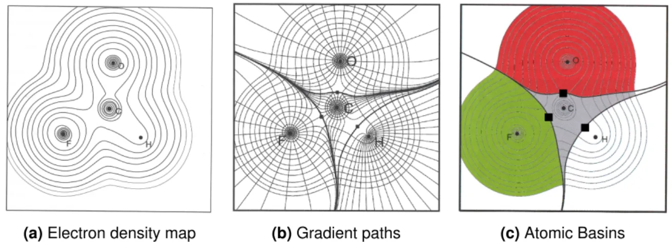
A further and very general approach for a comprehensive investigation of more properties than only the charge has been developed by R. Bader and coworkers with the Quantum Theory of Atoms in Molecules (QTAIM) starting in the 1970s.64 Differences in the electron density are used to topologically divide greater assemblies such as molecules, complexes and more extended systems into single molecular parts for defining and evaluating electronic properties and bonding schemes.65,66 The general procedure of the evaluation is demon- strated in Figure 3.2. At first, an electron density map is calculated from the determinant wavefunction, which can be constructed via the Kohn-Sham orbitals of a DFT calculation.66 Next, subspacesΩshall be defined which allow to unequivocally break molecular properties down into properties of the constituent atoms.65 A concept therefore is the quantum atom defined by
∫︁
Ω
∇2ρ(r)dV = 0, (3.9)
and is based on the unambiguous assignment of a kinetic energy value and fulfillment of the virial theorem for the subspaceΩ.64aTechnically, these subspaces are located by calculating the gradient ∇ρ at each point in space, with a map of gradient paths following the steep- est ascent shown in Figure 3.2.65The sketch clearly shows surfaces which are not crossed by any gradient paths, but all paths are bent and run parallel to the surface.66 These zero- flux surfaces define the borders between the mononuclear atomic basins in consistency with equation 3.9.64a,65,66 The space is thus completely filled by non-penetrating atomic basins with interacting atoms possessing a common zero-flux surface (see Figure 3.2).65,66 The as- signment of atomic basins also allows to define single atomic properties like the charge66
q(A) =ZA−N(A) =ZA−
∫︁
ΩA
ρ(r)dV, (3.10) calculated from an integration of the electron density within the boundaries of an atomic basin ΩAand subtraction from the nuclear chargeZAof the corresponding atom A.
In addition to the surfaces, the gradient picture Figure 3.2 reveals special points, which define the start or end of gradient paths. As such, they are characterized by a vanishing gradient
∇ρ.65Based on the second derivative ofρ, i.e. the eigenvalues or curvature valuesλ1toλ3of the hessian matrix, the critical points can be classified66and two groups shall be discussed in detail. Most gradient paths end at a nucleus’ position. These nuclear critical points (NCP) are local maxima of the electron density and thus all curvature values are negative.65,66 A second type of critical points, the bond critical points (BCP), is represented by the black squares in Figure 3.2. Located on a zero-flux surface, they mark a minimum of the bond path connecting
3.3 Charges and QTAIM-Analysis 16 two bonded atoms and are thus saddle points on the electron density surface. While the NCP together with the bond paths inherently define the molecular structure, the properties of the BCP and the behavior of the electron density along the bond path can be exploited to analyze the atoms’ interaction.66
(a)Electron density map (b)Gradient paths (c)Atomic Basins
Figure 3.2:Concept of a QTAIM-Analysis demonstrated for formylfluoride: The electron density map (a) is used to calculate gradient paths (b). Based on them the atomic basins and critical points (c) are assigned. Figures are taken from [65].
Three selected parameters of the BCP shall be discussed in this context: the electron den- sityρ, its laplacian∇2ρand the delocalization index DI. First of all, the electron density ρat the BCP is a measure for the bond order and correlated to the bonding energy.64c Usually, ρ >0.2 a.u. for covalent bonding and smaller than 0.1 a.u. for closed-shell interactions such as van-der-Waals bonds or hydrogen interactions.66 The laplacian∇2ρ, defined as the trace of the hessian and thus the sum of the curvature values, analyzes how the electron density changes in the spatial directions.66 If depletion along the bond path exceeds concentration perpendicular to it, ∇2ρ>0 and the interaction is characterized as weak closed-shell bond- ing. For covalent bonds however, the interaction between the basins is strong, such that concentration is dominant and the laplacian is less than zero.64d Finally, the delocalization index DI is a measure for the number of electron pairs exchanged between two mononuclear atomic basins in the molecule.67It is obtained by an integration over the exchange density for the two basins involved
DI(Ω1,Ω2) = 2·F(Ω1,Ω2) =−2∑︁
i
∑︁
j
Sij(Ω1)Sji(Ω2) (3.11)
with the fermi correlation F(Ω1,Ω2) and the overlap integral Sij(Ωk) for two orbitals within the basin Ωk.66,67 For covalent bonds, the DI equals the bond order with values of 0.85− 1.0 obtained for a C−C bond. On the other hand, small DIs usually indicate non-covalent interactions. All three measures for the interactions, ρ, ∇2ρand DI, have been exploited to evaluate the bonding within the complexes of investigation.
17
4 Results
4.1 Synthesis and Characterization of Uranium Bipyridine Complexes
4.1.1 Synthesis
U(VI)-2,2’-bipyridine compounds from aqueous media have been investigated by S. Schöne as part of his doctoral research with a publication in preparation.68 Thus, the focus of the present work is a complementing study investigating the influence of non-aqueous solvents.
The reaction of UO2Cl2·H2O with 2,2’-bipyridine (bipy, bipyridine) in non-aqueous media as sketched in Scheme 4.1 led to the formation of various crystalline uranium bipyridine com- plexes. In a first step, different stoichiometries of 2,2’-bipyridine relative to the uranium con- tent have been applied, altering the metal to ligand (M:L) ratio from equimolar to 1:3. Next, the bright yellow powder of [UO2Cl2(Bipy)(H2O)] (1) obtained from these reactions has been exposed to water and several organic solvents.
N N
+
N N
U O O
Cl HCl2O UO2Cl2 H2O Aceton
n - (n-1)Bipy N N
U O O
Cl ClSol -H2O
Sol
1 2, 3, 4
Scheme 4.1:Synthesis route for the formation of [UO2Cl2(Bipy)(Sol)]-complexes with variable n=1,2,3. Crystal structures could be obtained for Sol = EtOH (2), THF (3), Me2CO (4).
Ethanol (EtOH), acetone, tetrahydrofurane (THF) and acetonitrile (MeCN) have been elected as the organic solvents in order to determine the influence of different donor functions. As a member of N-donor solvents, MeCN has been used. The results for this solvent will be separately discussed in 4.1.5. Apart from that, variousO-donors have been tested. Ethanol has been selected due to its high polarity and proticity. As a yet polar, but non-protic solvent, acetone was used. Finally, THF has been applied as a solvent with only moderate polarity.
The powder of 1 readily dissolves in water and ethanol forming a bright yellow solution.
Crystals could be obtained from the ethanolic solution by a slow evaporation of the solvent, showing an exchange of the attached water for a solvent molecule according to Scheme 4.1 (analysis see 4.1.3). [UO2Cl2(Bipy)(EtOH)] (2) could also be directly synthesized as a bright yellow, crystalline precipitate using a M:L ratio of 1:1 in ethanol (see appendix).
4.1 Synthesis and Characterization of Uranium Bipyridine Complexes 18 A completely different dissolution behavior has been observed for aprotic solvents (Sol) (ace- tone, THF, toluene, acetonitrile). [UO2Cl2(Bipy)(H2O)] was almost insoluble in these solvents forming colorless solutions with precipitate still present even after application of heat. Pro- ticity is obviously a crucial factor for dissolving the complex [UO2Cl2(Bipy)(H2O)]. However, heating under reflux followed by slow evaporation of the solvent led to the formation of yellow crystals which have been subsequently analyzed (see 4.1.3).
4.1.2 Characterization of [UO2Cl2(Bipy)(H2O)]
The precipitates formed from solutions with different M:L ratio were thoroughly analyzed.
Comparison of powder diffraction patterns (see Figure 4.1a) revealed that the identical com- pound is formed independent of the excess of bipyridine applied.
(a)P-XRD patterns (b)IR spectra
Figure 4.1:Characterization of the solid compound [UO2Cl2(Bipy)(H2O)]. Powder diffraction pat- terns for the products applying different M:L ratio are shown in (a) and compared to a diffraction pattern simulated from single crystal data of [UO2Cl2(Bipy)(H2O)] (data by S.
Schöne). In (b), the IR spectrum of the synthesis product is compared to a spectrum of [UO2Cl2(Bipy)(H2O)] from an aqueous synthesis (data by S. Schöne).
The product could be clearly identified as a pure [UO2Cl2(Bipy)(H2O)] phase based on the good agreement with the reflex positions of a diffraction pattern calculated from a single crystal data set of [UO2Cl2(Bipy)(H2O)]. These crystals have been previously obtained by S.
Schöne from an aqueous system, rendering a crystallization of the current product for a full characterization obsolete. Instead, the crystal data obtained by S. Schöne has been used for further comparison.
In order to exclude a major contamination with amorphous substances, the product has been further analyzed by elemental analysis and IR spectroscopy. Assuming the products from re- actions with different M:L ratio to be identical, only the precipitate of the reaction with a ratio
4.1 Synthesis and Characterization of Uranium Bipyridine Complexes 19 of 1:3 has been analyzed by elemental analysis. The data (see Table A.1, appendix) con- firm the formation of [UO2Cl2(Bipy)(H2O)]. However, the slightly enhanced amount of carbon may indicate adherent organic impurities. A closer examination of the IR spectra allowed to identify these impurities as traces of the solvent acetone (see Figure 4.1b). Besides showing the characteristic vibrations of water (νOH = 3330 cm−1) and the asymmetric vibration of the uranyl unit (νas,UO2+
2 = 928 cm−1), the spectrum additionally contains signals at 1707 cm−1 and 1360 cm−1, which did not appear for [UO2Cl2(Bipy)(H2O)] formed in an aqueous synthe- sis. These vibrations are marked in orange in Figure 4.1b and can be assigned toνC−−Oand δC−CH3 of the solvent acetone, respectively.
In conclusion, an analysis via P-XRD, IR and EA revealed that only one stable compound, [UO2Cl2(Bipy)(H2O)] (1), with a good purity is formed from the uranium salt UO2Cl2·H2O and bipyridine in acetone, even if an excess of bipyridine is present.
4.1.3 Characterization of [UO2Cl2(Bipy)(Sol)]
The crystal samples obtained by dissolution of 1 in various solvents have been examined by a microscope with a polarized filter and suitable single crystals have been analyzed by SC-XRD. The data of the crystal structure solution and refinement are listed in Table A.2.
The complexes formed from solutions of ethanol, THF and acetone are very similar regarding the overall structure and have been compared to the analogous water complex in Table 4.1 in terms of structural parameters describing the coordination sphere of the uranium atom. For all three solvents S, a complex [UO2Cl2(Bipy)(Sol)] has been formed following Scheme 4.1, i.e. an exchange of the water molecule for a solvent molecule occurred.
The almost linear uranyl unit is equatorially coordinated in a distorted pentagonal-bipyrami- dal fashion by two chloride ions, the bidentate bipyridine ligand and the corresponding sol- vent molecule. Although most published uranium bipyridine complexes possess a hexagon- al-bipyramidal coordination due to a bidentate carboxylate as the anion, the pentagonal- bipyramidal coordination is generally common for uranyl complexes.19 A common feature of the uranyl unit within a pentagonal-bipyramidal environment is the small deviation of the uranyl Oyl−U−Oyl-angle from linearity.19Such a behavior has been confirmed for previously published uranyl bipyridine complexes with pentagonal-bipyramidal geometry30,31 and is also observed for the current complex series with Oyl−U−Oyl-angles ranging between 176.6∘and 179.3∘.
The pentagonal bipyramidal coordination polyhedron is slightly distorted due to the twist of the bipyridine N−U−N-plane relative to the Cl−OS−Cl-plane as stated by the plane-to-plane twist angle ∆αBipy.
![Figure 4.1: Characterization of the solid compound [UO 2 Cl 2 (Bipy)(H 2 O)]. Powder diffraction pat- pat-terns for the products applying different M:L ratio are shown in (a) and compared to a diffraction pattern simulated from single crystal data of [UO 2](https://thumb-eu.123doks.com/thumbv2/1library_info/4565383.1599811/27.892.115.797.498.795/characterization-compound-diffraction-products-applying-different-diffraction-simulated.webp)
![Figure 4.4: Simulated complex [UO 2 Cl 2 (Bipy)(Sol)] with Sol=acetonitrile (MeCN) (a) and the 1:2 complex [UO 2 Cl 2 (Bipy) 2 ] (b)](https://thumb-eu.123doks.com/thumbv2/1library_info/4565383.1599811/35.892.147.753.861.1066/figure-simulated-complex-bipy-acetonitrile-mecn-complex-bipy.webp)
