Czech Technical University in Prague
Faculty of Nuclear Sciences and Physical Engineering
Department of Nuclear Reactors
Feasibility study on high-conversion Th-U233 fuel cycle for current generation of PWRs
Ph.D. thesis
Author: Ing. Daniela Baldová Supervisor: Emil Fridman, Ph.D.
Co-supervisor: Ing. Jan Frýbort, Ph.D.
Prague, 2014
Abstract
This thesis explores a possibility of designing a high conversion (HC) Th-U233 core for current generation of Pressurized Water Reactors (PWRs). Increasing the conversion ratio in existing PWRs can potentially improve the utilization of natural resources, through the exploitation of vast thorium reserves and reduction in natural uranium demand.
HC can be achieved through the use of heterogeneous seed-blanket (SB) Th- U233 fuel assembly design where the supercritical seed works as a neutron supplier, while the subcritical blanket acts as U233 breeder. One of the main challenges associated with the heterogeneous SB fuel assembly designs is a significant power imbalance between the seed and blanket regions caused by the concentration of fissile material primarily in the seed zone and consequently requiring a substantial reduction in the core average power density.
The main objectives of the thesis are twofold: 1) to design a high conversion SB Th-U233 fuel assembly which is directly retrofittable into existing PWRs without introducing significant modifications into the core and plant design; 2) to estimate the reasonably achievable core power density level at which reactor safety is not compromised.
The first objective is accomplished by performing assembly-level parametric study. Based on the results, a number of SB fuel assembly configurations are selected for the following whole-core analysis.
The reasonable achievable core power density level at which reactor safety is not compromised is estimated by performing 3D full core coupled neutronic and thermal- hydraulic (T-H) analysis of a typical PWR core fully loaded with HC Th-U233 SB fuel. The results demonstrate that in principle the Th-U233 PWR core can be operated without exceeding the main safety limits at reduced power density of 60 W/cc in three-batch annual fuel cycle. However, it was shown that the sustainable mode cannot be fully realized. Still the results indicate that potential saving of natural resources can be achieved with HC Th-U233 fuel cycle.
Keywords: High Conversion Fuel Cycle, Th-U233 fuel, Seed-blanket fuel assembly
Declaration
I do solemnly declare that I have written the presented research thesis by myself under the direction of my supervisor Emil Fridman, Ph.D, and without the aid of unfair or unauthorized resources.
In Prague,
Daniela Baldová
Acknowledgements
I would like to express my great appreciation to Dr. Emil Fridman, my supervisor, for his patient guidance, encouragement, and support in all aspects of this work.
I am also grateful for the assistance and useful critiques given by Dr. Jan Frýbort (Faculty of Nuclear Sciences and Physical Engineering, CTU in Prague) during the thesis preparation.
Special thanks to Dr. Sören Kliem, head of the department of Reactor Safety, HZDR, for providing me with all the necessary facilities and financial assistance during my stay here.
Advice given by Mr. Reuven Rachamin has been a great help in my research.
I am deeply thankful to Dr. Yurii Bilodid and Dr. Silvio Baier for their help not only with the DYN3D code.
Finally, I would like to thank my family and my friends for their support and encouragement throughout my study.
Table of contents
Abstract ... 1
List of figures ... 9
List of tables ... 11
Abbreviations ... 13
Chapter 1. Introduction ... 15
1.1 Background ... 15
1.2 Overview of advantages and drawbacks of Th-based fuels ... 16
1.3 Historical Review of the Th Use in LWRs ... 18
1.4 Recent Studies on the Potential Use of Th fuel in LWRs ... 19
1.4.1 Open vs. closed fuel cycle ... 20
1.4.2 Homogeneous vs. heterogeneous fuel design ... 20
1.4.3 Once-through fuel cycle aimed at reducing the proliferation ... 21
1.4.4 Closed fuel cycle aimed at Pu incineration ... 23
1.4.5 HC fuel cycle aimed at improvement of fuel utilization ... 23
1.5 Thesis objectives ... 25
Chapter 2. Analysis tools ... 27
2.1 2D level analysis tools ... 27
2.2 3D level analysis tools ... 33
Chapter 3. Assembly level analysis ... 35
3.1 Calculation methodology ... 35
3.1.1 Neutronic analysis ... 35
3.1.2 T-H analysis ... 36
3.2 Description of the reference HC Th-U233 SB PWR fuel assembly ... 38
3.3 Parametric neutronic and T-H calculations ... 45
3.4 Selection of SB configurations ... 52
Chapter 4. Full core analysis ... 57
4.1 Description of the HC Th-U233 PWR core design ... 57
4.1.1 Core loading pattern ... 57
4.1.2 T-H constraints ... 57
4.2 Analysis methodology ... 58
4.2.1 Homogenized cross sections generation ... 59
4.2.2 Specification of the limiting T-H criteria ... 61
4.3 Results of the 3D full core calculations ... 62
4.3.1 Selected SB configurations ... 62
4.3.2 Modified configurations ... 69
4.3.3 Core average reactivity coefficients ... 73
Chapter 5. Fuel cycle consideration ... 75
5.1 Analysis methodology ... 76
5.2 Material flow in HC SB fuel cycle ... 77
5.3 Natural uranium utilization ... 82
Chapter 6. Summary and future work ... 85
6.1 Thesis Summary ... 85
6.2 Future work ... 87
References ... 89
Appendix A ... 93
A.1 Power density distribution ... 93
A.2 TCL distribution ... 97
A.3 MDNBR distribution ... 101
A.4 Void fraction distribution ... 105
List of figures
Fig. 1.1. The η-factor of U-233, U-235 and Pu-239 depending on incident neutron
energy (based on JEFF-3.1.1) ... 16
Fig. 1.2. Th transmutation chain (IAEA, 2005) ... 18
Fig. 1.3. Schematic view of SBU and WASB assembly designs (IAEA, 2005) ... 22
Fig. 1.4. Heterogeneous Th-U233 SB fuel assembly designs ... 24
Fig. 2.3. Comparison of k-inf and FIR, HELIOS vs. SERPENT ... 31
Fig. 2.4. Comparison of actinide concentration, HELIOS vs. SERPENT ... 32
Fig. 2.5. Pin-by-pin power distribution for 1/8th FA at 0 MWd/kg ... 33
Fig. 2.6. DYN3D structure ... 34
Fig. 3.1. FIR vs. burnup, variable blanket pin radius ... 40
Fig. 3.2. U233 mass vs. burnup, variable blanket pin radius ... 41
Fig. 3.5. Power share between seed and blanket vs. burnup ... 43
Fig. 3.6. Reference SB fuel assembly: radial layout ... 44
Fig. 3.7. MDNBR vs. power density and Tin ... 48
Fig. 3.8. Maximum TCL vs. power density Tin ... 49
Fig. 3.9. Maximum Tout vs. power density and Tin ... 50
Fig. 3.10. Maximum outlet void fraction vs. power density and Tin ... 51
Fig. 3.11. Power density, W/cc – Case 1 ... 53
Fig. 3.12. Power density, W/cc – Case 2 ... 54
Fig. 3.13. Power density, W/cc – Case 3 ... 55
Fig. 3.14. Power density, W/cc – Case 4 ... 56
Fig. 4.1. Core loading pattern ... 58
Fig. 4.2. Nodalization of SB fuel assembly in DYN3D code ... 58
Fig. 4.3. DYN3D cross section calculation scheme ... 60
Fig. 4.4. Differences in k-inf, HELIOS vs. DYN3D ... 61
Fig. 4.5. Pumping power vs. mass flow rate ... 63
Fig. 4.6. Pressure drop vs. mass flow rate ... 63
Fig. 4.7. CBC vs. burnup ... 65
Fig. 4.8. CBC vs. burnup, Cases 3.1 and 4.1 ... 70
Fig. 4.9. Power density, W/cc – Case 3.1 ... 71
Fig. 4.10. Power density, W/cc – Case 4.1 ... 72
Fig. 5.1. Microscopic capture XS of Th232, U234, and U236 (ENDF B-VI.8) ... 76
Fig. 5.2. Material flow diagram for U recycling ... 77
Fig. 5.3. Fissile material content in discharged fuel after 7 years cooling ... 79
Fig. 5.6. Main fuel components mass flow during recycling ... 81
Fig. 5.7. Flow diagram of power generation ... 83
Fig. A.1. Power density, W/cc – Case 1 ... 94
Fig. A.2. Power density, W/cc – Case 2 ... 94
Fig. A.3. Power density, W/cc – Case 3 ... 95
Fig. A.4. Power density, W/cc – Case 4 ... 96
Fig. A.5. TCL,°C – Case 1 ... 97
Fig. A.6. TCL, °C – Case 2 ... 98
Fig. A.7. TCL – Case 3 ... 99
Fig. A.8. TCL – Case 4 ... 100
Fig. A.9. MDNBR – Case 1 ... 101
Fig. A.10. MDNBR – Case 2 ... 102
Fig. A.11. MDNBR – Case 3 ... 103
Fig. A.12. MDNBR – Case 4 ... 104
Fig. A.13. Void fraction – Case 1 ... 105
Fig. A.14. Void fraction – Case 2 ... 106
Fig. A.15. Void fraction – Case 3 ... 107
Fig. A.16. Void fraction – Case 4 ... 108
List of tables
Table 2.1: Summary of 11×11 SB fuel assembly parameters ... 30
Table 3.1: Reference PWR core: summary of the main design parameters ... 39
Table 3.2: Th232 in blanket: one-group σa and absorption reaction rates ... 42
Table 3.3:Reference SB fuel assembly: summary of the main design parameters ... 44
Table 3.4: FIR and initial seed U233 content vs. average power density and Tave ... 46
Table 3.5: Summary of the selected SB configurations for the full core analysis ... 52
Table 4.1: Summary of the branch-off parameters ... 59
Table 4.2: FIR and discharge burnup, Cases 1-4 ... 66
Table 4.3: Initial U233 mass load ... 66
Table 4.4: MDNBR calculated for hot channels at BOC ... 68
Table 4.5: Summary of the limiting T-H parameters, four selected SB configurations (Cases 1-4) ... 68
Table 4.6: Operating parameters of the modified SB configurations ... 69
Table 4.7: FIR and discharge burnup, modified configurations (Cases 3.1 and 4.1) .. 70
Table 4.8:Initial U233 mass load ... 70
Table 4.9: Summary of the limiting T-H parameters, modified SB configurations (Cases 3.1 and 4.1) ... 73
Table 4.10: Summary of the core average reactivity feedback parameters ... 74
Table 5.1: Initial Pu isotopic vector ... 77
Table 5.2: U isotopic vector in discharged fuel after 7 years cooling* ... 78
Table 5.3: U mass balance ... 79
Table 5.4: Summary of material flow at BOL and EOL for SB Cycles1 ... 81
Table 5.5: Total energy generated per core ... 83
Table 5.6: Mass balance* ... 84
Table 6.1: Comparison of the major design parameters, reference all-U PWR vs. HC Th-U233 PWR ... 87
Abbreviations
2D Two dimensional
3D Three dimensional
BOL Beginning of Life
BU Burnup
CHF Critical Heat Flux
CR Conversion Ratio
DC Doppler Coefficient
DNBR Departure from Nucleate Boiling Ratio EFPD Effective Full Power Days
EOL End of Life
FIR Fissile Inventory Ratio
GIF Generation IV International Forum
HM Heavy Metal
IAEA International Atomic Energy Agency
LWBR Light Water Breeder Reactor
LWR Light Water Reactor
MDNBR Minimum Departure from Nucleate Boiling Ratio
NLRM Non-Linear Reactivity Model
NU Natural Uranium
ONB Onset of Nucleate Boiling
pcm percent mili rho (Reactivity change of 105 ∆ρ)
ppm parts per million
PWR Pressurized Water Reactor
R&D Research and Development
RTF Radkowsky Thorium Fuel
SB Seed Blanket
SBU Seed Blanket Unit
TCL Central Line Temperature
T-H Thermal-Hydraulic
WASB Whole Assembly Seed and Blanket
XS Cross-section
Chapter 1. Introduction
1.1 Background
World population growth has been one of the issues of the recent decades in terms of future energy needs and of the environmental conditions of the planet. In order to preserve the prosperity and peace on our planet we have to keep energy available and affordable. Nowadays, there are basically three energy options:
renewable, fossil, and nuclear. The renewable energy sources - especially wind and solar - are unreliable by nature of their occurrence and have a limited potential to satisfy world energy demand. However fossil fuel is presently the most used energy resource which has the ability to satisfy the present energy demand, but cannot neglect environmental hazard due to the production of CO2. By contrast, nuclear energy is the largest source of emission-free energy. The nuclear energy is cost- effective and has potential to meet ever-increasing demands for word's electricity supply. The nuclear energy, dominated by Light Water Reactors (LWRs) comprising Pressurized Water Reactors (PWRs) and Boiling Water Reactors (BWRs), is currently based on burning uranium fuel in a once-through fuel cycle achieving relatively low natural uranium (NU) utilization of about 0.6% (Greenspan, 2012).
The question of better utilization of natural resources, safety, reliability, and proliferation-resistance, gave rise to two main international projects, namely Innovative Nuclear Reactors and Fuel Cycles Programme (INPRO) initiated by the IAEA and the US-led Generation IV International Forum (GIF).
Sustainable utilization of natural resources is one of the main goals set by the GIF (OECD, 2014). Current and future generations of LWRs can be modified or designed to achieve or approach the sustainability goals. Taking advantage of proven technologies and existing infrastructure would minimize the R&D expenditures. For instance, by making use of advanced LWR designs with innovative fuel cycles a more practical and cost effective pathway could be opened, at least in the near term before fast reactor technology becomes sufficiently mature. Recent studies performed in Japan by JAEA and Hitachi (EPRI, 2012) showed that self-sustainable operation of BWR with respect to fissile material is possible. This was achieved by modifying a BWR including reducing the fuel pins lattice pitch, increasing the core average void fraction and utilizing an axially heterogeneous core structure.
However, the Th-U233 fuel is the only combination practically capable of high conversion (HC) in thermal neutron spectrum, as U233 has a neutron yield (η-factor) per neutron absorbed greater than 2.0 over a wide range of the thermal neutron energies, unlike the other common fissile isotopes U235 and Pu239 (Fig. 1.1).
Since Th is 2 to 4 times more abundant than U (IAEA, 2005), Th-based fuels used in HC fuel cycle in existing PWRs can potentially improve the utilization of natural resources through the exploitation of vast Th reserves and reduction in NU demand.
Fig. 1.1. The η-factor of U-233, U-235 and Pu-239 depending on incident neutron energy (based on JEFF-3.1.1)
1.2 Overview of advantages and drawbacks of Th-based fuels
Besides the aforementioned advantages, there are several additional benefits of using Th as the fertile material (IAEA, 2005):
- Th232 has higher thermal capture cross section in comparison to U238;
therefore, has higher fertile to fissile conversion rates.
- ThO2 is chemically more stable and has higher radiation resistance than UO2, which may allow longer in core-residence times.
- ThO2 has favorable thermo-physical properties because of the higher thermal conductivity and lower coefficient of thermal expansion as compared to UO2. - The melting point of ThO2 is about 500 °C higher than that of UO2.
- ThO2 is inert and does not oxidize unlike UO2.
- Being a lighter element than U238, Th232 produces virtually no transuranium isotopes.
The disadvantages Th as a fuel (IAEA, 2005):
- Th does not contain any fissile isotope. Therefore, to startup the Th fuel cycle, an initial “fissile driver” component must be provided.
- For production of ThO2, a higher sintering temperature (>2000°C) is required than that of UO2, due to its high melting point (3350°C).
- ThO2 is relatively inert and hence does not dissolve easily in concentrated nitric acid. Therefore, the reprocessing of Th based fuel is more complicated as compared to U based fuel. The chemical method used for reprocessing of spent Th based fuel is called THOREX (THORium-uranium Extraction) process (Gresky, 1955). Till date, the THOREX process was used mostly on laboratory and pilot reactor scale. Therefore, the experience with THOREX process is limited as compared to that of commercial PUREX process (Anderson and Asprey, 1960).
- By irradiation of Th-based fuel, significant amount of U232 is created. U232 has half-life of only 69.8 years and is associated with strong gamma emitting radionuclides in its chain, Bi212 and Tl208 with very short half-life (Fig. 1.2) - This significantly complicates spent Th fuel handling operations such as
reprocessing, fuel fabrication, transport, disposal, etc.
- U233 generated from Th232 is potentially weapons usable material. However, high energy γ emitters mentioned above provide a certain degree of proliferation self-protection (Laughter et al., 2002).
- The database and experience with Th fuel cycle are limited in comparison with that of U fuel cycle.
- Existence of so-called protactinium effect. Pa233 may not only decay to the fissile U233, buy may be also converted to Pa234. This leads to the significant loss of new fissile material U233. Moreover, it causes reactivity increase after shutdown, when Pa234 is no longer created and all Pa233 decays to U233.
Fig. 1.2. Th transmutation chain (IAEA, 2005)
1.3 Historical Review of the Th Use in LWRs
The feasibility of using Th as a fertile material in LWRs has been explored since 1960s and the interest in it has lasted to the mid-1970s. During this period, several Th- based fuel design options were investigated and some even resulted in whole core demonstrations.
- BORAX-IV (2.5 MWe) BWR (IAEA, 2005) experimental core located in Idaho and operated by Argon National Laboratory between 1956 and 1958 demonstrated the feasibility of stable operation with ThO2-UO2 fuel.
- Elk River (IAEA, 2005) was a 24 MWe BWR (1964-1968) built by Allis- Chalmers in Minnesota. The reactor operated satisfactorily but its limited power and cooling system corrosion led to its shut down.
Both reactors, BORAX-IV and Elk River were using high density ThO2-UO2 fuel pellets containing 4-7% UO2.
- Indian Point 1 (IAEA, 2005), a 285 MWe PWR (1962–1980) built by Consolidated Edison in New York led the way in the use of fuel mixture of Th and highly enriched (93%) U in the first U233 breeding core.
- The Shippingport Light Water Breeder Reactor was developed by Pittsburgh Naval Reactors Office in framework of the Light Water Breeder (LWBR) program which aimed to confirm the feasibility of breeding of net U233 in the thermal spectrum (Connors et al., 1978). The reactor core consisted of seed-
blanket fuel assemblies surrounded by 15 reflector assemblies. Every fuel assembly was subdivided into two standalone sub-assemblies: a movable central seed region containing U233 and the peripheral stationary blanket region containing mostly Th. In LWBR movable seed rods were introduced as a replacement for control rods in order to further improve the neutron economy, and minimize neutron losses. The reactivity was controlled by moving up and down seed sub-assembly inside the blanket sub-assembly. The reactor was operated from 1977 until 1982 and the fuel achieved a maximum burnup of 60 GWd/t. The design lifetime for LWBR was 1200 Effective Full Power Days (EFPD) assuming three batch fuel management. The core was operated with the power output of 60MWe. The results of analyses on spent LWBR fuel confirmed that the ratio of the fissile content of the fuel at the end of operation to that at the beginning of operation was about 1.0139. It should be mentioned that the LWBR program provided the most extensive experience with Th based fuel cycle in LWRs.
Despite of its potential advantages, the interest in Th based fuel cycle declined significantly, and by the 1980s most of the projects with Th fuel cycle had been terminated. One of the reasons of this declined interest was that Th could not compete with the relatively cheap and well-established U fuel cycle.
1.4 Recent Studies on the Potential Use of Th fuel in LWRs
In recent years there has been a renewal of interest in Th-based fuel cycles, particularly for commercial PWRs, primarily motivated by their potential:
- To improve the proliferation resistance of spent fuel not only by producing lower amount of Pu but also by reducing its quality.
- To efficiently incinerate excess reactor-grade Pu (RG-Pu) and weapons-grade Pu (WG-Pu) and to reduce long-term radioactivity and toxicity of the spent fuel storage.
- To improve the fuel utilization by reducing the NU requirements.
Several R&D projects were aimed at investigation of Th-based fuel cycles for LWRs. The projects differ not only in the extent and depth of the R&D effort (from simplified study to a detailed assembly/core/cycle design), but also in fuel cycle strategies (once-through cycles vs. reprocessing), and fuel design options (homogeneous fuel vs. heterogeneous fuel). Noting that introducing Th component of
the fuel necessitates the use of a “fissile driver” component, several options were considered: enriched U, RG-Pu, WG-Pu, and a mixture of transuranium isotopes (TRU).
The specified fissile driver, cycle strategy, and fuel design were selected based on a design objective, usually related to one of the three aforementioned reasons for Th utilization (proliferation, reduction of long-term radioactivity, reduction of NU requirements) or their combination.
1.4.1 Open vs. closed fuel cycle
The main design constraint, which influences the design solutions, is the choice of closed (reprocessing) vs. open (once-through) fuel cycle. In the case of the open cycle in LWRs, the U233 is bred and fissioned in situ, without involving chemical separation of U233; therefore, there is always need for make-up fissile material. The open fuel cycle avoids the complex reprocessing processes and other complications associated with re-fabrication of highly radiotoxic U233–based fuels. Thus, the benefit from the produced U233 depends on burnup only, which is required to be as high as possible. In the case of the closed fuel cycle, the bred U233 and Th are recovered by chemical reprocessing of the spent fuel. As shown in (Shapiro et al., 1977), the use of Th in closed fuel cycle can improve the utilization of natural resources and reduce associated costs. Contrary to aforementioned closed fuel cycle, the open cycle avoids the handling of “dirty” U233 outside the core and therefore is considered to be safe from both, an environmental and non-proliferation point of view. Due to the mentioned advantages, most of the recent studies have focused on the open fuel cycle.
1.4.2 Homogeneous vs. heterogeneous fuel design
There are two main fuel assembly design options that have been under discussion in recent studies for the Th fuel cycle in LWRs: homogeneous and heterogeneous. In the homogeneous approach, the U fuel rods are directly replaced by a fuel rods containing either ThO2-UO2 or ThO2-PuO2 mixture. The heterogeneous approach employs seed-blanket (SB) fuel configuration, where U and Th fuel parts are spatially separated either within a given assembly, or between assemblies. Although the homogeneous concept is attractive by its simplicity (without the need for any modifications of the core parameters), the results of several investigations, indicated
clearly that for the open cycle option and a homogeneous design, NU savings cannot be achieved. For instance, a comprehensive study (Galperin et al., 2002) on the use of the homogeneous ThO2-UO2 mixture in current PWR was carried out with the aim of reducing NU requirement and proliferation potential of the fuel cycle. From the obtained results it is evident that (in case of a similar discharged burnup) the increase of the proliferation resistance of ThO2-UO2 mixture as compared to all-U fuel is only moderated. In addition, it was shown that a homogeneous ThO2-UO2 mixture does not provide any significant improvement in the fuel cycle; on the contrary, it will increase the NU requirement, thus resulting in a waste of this natural resource. The similar conclusion was also found in studies (Gungor, 1990; Clarno, 1999). In (Hyung-Kook Joo et al., 2004), alternative applications of homogeneous Th-U fuel in LWRs were investigated with the aim of enhancing the economic potential of Th-based fuels. The three alternative ThO2-UO2 fuel cycles were considered: a Th-U fuel with a relatively low U235 enrichment (< 20 wt%), a mixed core of duplex ThO2-UO2 and UO2 fuels, and use of Th-U fuel in a small and medium LWR with a 5-yr cycle length. The results of core analysis indicated that there is no improvement in NU utilization and that the ThO2-UO2 fuel cannot compete economically with UO2 fuel. However, it was shown that the U utilization factor for the Th-U cores increases with fuel cycle length, while those for the U decrease. Hence, it can be assumed that the further improvement in economy will be achieved, when Th based fuel is used with longer fuel cycle schemes. It should be mentioned that the mixed core of duplex ThO2-UO2 and UO2 fuels which, in fact, does not belong to homogeneous fuel category provides slight increase in NU utilization by 3 to 6% compared to ThO2-UO2 and UO2 cores. The homogeneous design studies have also embodied micro-heterogeneous design where the U and Th fuel are spatially separated within a given fuel rod. In (Shwageraus et al., 2005) it was demonstrated that the spatial separation of the U and Th parts of the fuel on the order of a few millimetres to a few centimetres can improve the achievable burnup of the Th-U fuel designs through more effective converting of Th232 to U233.
In contrast to homogeneously mixed Th-U fuel, the micro-heterogeneous fuel has a potential to be competitive economically with commercial UO2 fuel.
1.4.3 Once-through fuel cycle aimed at reducing the proliferation
The investigations of Th-U homogeneous mixture in once-through fuel cycle indicate that in order to avoid penalty on NU utilization and associated fuel cycle
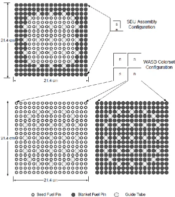
costs, the U and Th parts of the fuel should be spatially separated. Two heterogeneous fuel design options for the implementation of Th fuel cycle in LWRs have been examined under the Nuclear Energy Research Initiative (NERI) funded by the United States Department of Energy. The two approaches are: 1) Seed-Blanket Unit (SBU, also known as Radkowsky Th Fuel (RTF) developed at Ben-Gurion University (Israel) (Radkowsky and Galperin, 1998)), which can replace the conventional PWR fuel assembly one-for-one (Fig. 1.3); 2) the Whole Assembly Seed and Blanket (Todosow et al., 2005) (WASB, the concept developed at MIT (USA)), where seed and blanket units each form one full-size PWR assembly (Fig. 1.3).
Fig. 1.3. Schematic view of SBU and WASB assembly designs (IAEA, 2005) The both fuel assembly designs were considered to be directly retrofittable into existing PWR assemblies with minimum changes in the core and plant design. Both the RTF and WASB concepts exhibit significant deterioration of the proliferation potential due to a substantial reduction in the produced Pu quantity and quality (the critical mass of RTF Pu is greater than for PWR Pu). For example, in case of RTF, the amount of Pu discharged per year can be reduced to 20% of that of a PWR. Moreover the RTF concept, as well as WASB concept, is competitive economically. Several studies also investigated whether Th based fuel possess advantages in an intermediate neutron spectrum (tight lattice). For instance, the results of (Iwamura et al., 1999)
showed that introducing Th based fuels designed in tight-pitch lattice do have several attractive characteristics, such as a more negative void coefficient and a higher fuel conversion ratio than corresponding U based fuels.
1.4.4 Closed fuel cycle aimed at Pu incineration
As aforesaid, Th based fuel can be also used for the purpose of incineration and or stabilization of excess RG-Pu and WG-Pu. The main objective of studies performed with focus on Th based cycles for reprocessing option was to maximize Pu destruction. The results of the studies reported in (Galperin et al., 2000; Shwageraus et al., 2004; Fridman and Kliem, 2011) demonstrated that both, homogeneous and heterogeneous fuel designs can achieve better Pu destruction rates and lower quality residual Pu vector in spent fuel than conventional U-Pu mixed oxide (MOX) fuel. For instance, in (Galperin et al., 2000) a heterogeneous SBU Pu-incinerator (also known as Radkowsky Th-Pu Incinerator - RTPI) was proposed for incineration of RG-Pu and WG-Pu and the results indicated that the Pu incineration rate is three times higher than that of the MOX core. In (Shwageraus et al., 2004) the Pu and transuranium (TRU) destruction efficiency of homogeneous Th-based fuels was investigated on a single fuel assembly level. The results of the study indicated that in case of Th-Pu fuel up to 75% of initially loaded Pu can be incinerated while in case of Th-TRU fuel the destruction efficiency of total TRU is limited by about 50%. The results of the full core analysis in (Fridman and Kliem, 2011) showed that in Th-Pu mixed oxide (TOX) PWR core, the Pu consumption is almost doubled as compared to that of MOX PWR core.
1.4.5 HC fuel cycle aimed at improvement of fuel utilization
HC Th-U233 fuel cycle implemented in the existing reactors can potentially improve the utilization of natural resources through the exploitation of vast Th resources and the reduction in NU demand, since the Th-U233 fuel is theoretically capable of achieving a HC ratio in the thermal neutron spectrum. The possibility of thorium utilization in HC fuel cycle in PWRs has been investigated in a number of scoping neutronic studies ( Kotlyar and Shwageraus, 2012; Shwageraus et al., 2009;
Yun et al., 2010). It was demonstrated through the assembly-level fuel depletion analysis that the HC ratio in PWRs can be achieved, in principle, via the use of heterogeneous Th-U233 SB fuel assembly designs, in which the fissile and fertile
materials are spatially separated from each other. In (Shwageraus et al., 2009) the SB fuel assembly design (Fig. 1.4.a) featuring a reduced assembly size, duplex seed pins, and a thorium hydride blanket fuel was developed. In the SB design investigated in (Yun et al., 2010), the SB fuel assemblies have typical PWR outer dimensions and the seed fuel pins do not form a distinct region in a fuel assembly but rather distributed among the blanket pins, as seen in Fig. 1.4.b. In (Kotlyar and Shwageraus, 2012), the arrangement of the seed and ThH2 blankets fuel pins in 11×11 (Fig. 1.4.c) and 17×17 (Fig. 1.4.d) fuel assemblies was optimized using a simulated annealing approach.
a. 11×11 (Shwageraus et al.,2009) b. 17×17 (Yun et al., 2010)
c. 11×11 d. 17×17
(Kotlyar and Shwageraus, 2012) Fig. 1.4. Heterogeneous Th-U233 SB fuel assembly designs
1.5 Thesis objectives
One of the main challenges associated with the aforementioned heterogeneous SB fuel assembly designs is a significant power imbalance between the seed and blanket regions caused by the concentration of fissile material mostly in the seed zone. A high power peaking in the seed region will most likely lead to exceeding the thermal- hydraulic (T-H) safety limits and therefore will necessitate a substantial reduction in the average core power density. However, despite their importance, T-H design and safety related issues were typically not considered in the earlier works. An attempt to estimate the achievable power density levels was done in a previous T-H feasibility study (Volaski et al., 2009) where a simplified T-H analysis of a single 11×11 SB fuel assembly was performed without taking the effect of the T-H feedback on neutronics into account.
The main objectives of this study are:
- To propose a design of HC SB Th-U233 fuel assembly which can be directly retrofit into existing PWRs without introducing significant modification into the core and plant design.
- To estimate the reasonably achievable power density level of PWR core fully loaded with HC Th-U233 SB fuel at which reactor safety is not compromised.
- To demonstrate feasible routes for generation of initial and makeup U233.
- To estimate potential savings of available resources that can be achieved with HC Th-U233 fuel cycle.
The objectives will be pursued according to the following steps:
- Assembly level depletion analysis of a number of SB configurations assuming several reduced power density levels and different inlet coolant temperatures.
- 3D single assembly thermal-hydraulic (T-H) analysis aiming at the evaluation of major safety related parameters.
- Based on the results of the parametric studies described by previous two steps, a number of SB configurations will be selected for the subsequent more realistic full core analyses.
- Two-group cross sections (XS) generation for the selected SB configurations.
- Steady-state whole core coupled neutronic and T-H analysis of 100% Th- U233 fueled PWR aiming at the confirmation of the assembly level results with regards to the practically achievable power density.
- Assembly level depletion and decay analysis including U recycling.
The results of this study will be used to assess the basic operational feasibility of the HC Th-U233 PWR core from the neutronic and T-H point of view.
Chapter 2. Analysis tools
This chapter presents the computational tools used in the dissertation.
2.1 2D level analysis tools
In this study, all 2D assembly level calculations including the generation of homogenized two-group XS for a 3D full core analysis were performed using HELIOS-1.10. HELIOS is a well-known commercial deterministic neutron transport lattice code developed by Studsvik Scandpower (Studsvik Scandpower, 2008). The HELIOS transport solver is based on current coupling and collision probabilities (CCCP) method. The HELIOS code employs the 190-group cross section library based on ENDF/B-VI evaluated data files.
The system to be calculated in the HELIOS code (e.g. a fuel assembly) is built up by a cumulative coupling of the space elements (structures such as pin cells) by means of the interface currents, and the properties of the space elements are obtained from collision probabilities. These probabilities are evaluated by assuming the flat-flux approximation inside the sub-regions of the space elements. These sub-regions, which are in fact closed material areas, may be further subdivided in order to obtain a satisfactory spatial mesh for the flat-flux approximation.
The angular dependence of the aforementioned interface currents is taken into account by subdividing the structures into sectors, where the cosine currents are assumed. This angular representation between two structures is specified by choosing one of the coupling options (k) available in HELIOS. Presently, k ranges between -5 and 18, where k equals to 0 represents the most accurate but expensive option of direct collision probabilities over the entire geometry.
The HELIOS code capability for analyzing homogeneous Th-based fuels was already demonstrated in the past with the help of the code-to-code benchmark (Mittag and Kliem, 2011) and comparison with the experimental data (Björk et al., 2013) in the framework of the European LWR-DEPUTY project (Verwerft, 2007). However, the HC fuel assembly designs investigated in this dissertation are expected to be highly heterogeneous. For that reason, further verification of the HELIOS code regarding this matter is necessary.
In order to demonstrate the applicability of the HELIOS code for the analysis of heterogeneous Th-U233 fuel assembly designs, HELIOS was benchmarked against
the SERPENT code (Leppänen, 2013). SERPENT is a 3D continuous-energy Monte Carlo (MC) reactor physics code, recently developed at VTT Technical Research centre of Finland. The SERPENT code was especially developed for the reactor physics application. SERPENT runs significantly faster than other MC codes. The reasons for that are twofold: first, the use of the Woodcock delta-tracking (Leppänen, 2010) in a combination with a typical surface-to-surface ray-tracing in a geometry routine, and second, the use of the unionized energy grid (Leppänen, 2009) for all point-wise reaction cross sections. The SERPENT code has built-in decay and burnup routine which is based on the solving Bateman equations using the Chebyshev Rational Approximation method (CRAM) (Pusa, 2011). Each SERPENT update is benchmarked against MCNP by running a standard set of assembly calculation problems. The SERPENT 1.1.19. used in this study was validated by comparision to MCNP5 (Jeremy, 2003). The benchmark was carried out for six different geometry types (Leppänen, 2009a). The number of neutron histories was same for both codes. It was shown that the difference in effective multiplication factor is in the order of statistical accuracy from the reference results. Likewise, the discrepency in 4-group constants does not exceed significantly the statistical accuracy from the reference results. In general, the results show that the differences between the codes are well within the range of statistical accuracy and that the SERPENT code performes faster - in some of the investigated fuel types 50 times faster - than the MCNP code.
As mentioned, the SERPENT code has a burnup solver, and for that matter it can be used to verify the HELIOS code. A series of burnup calculations were performed for heterogeneous Th-U233 fuel assembly design adopted from the Volaski (2009).
The considered fuel assembly has an 11×11 pin lattice, and is subdivided into the two regions, namely, seed and blanket. The geometry and operating conditions of the fuel assembly are summarized in Table 2.1. The assembly layout is shown in Fig. 2.1.
All the fuel lattice calculations were carried out with the reflection condition. The SERPENT calculations were performed employing ENDF/B-VI.8 based XS library and using 100,000 neutron histories, 20 skipped and 250 active cycles. The HELIOS calculations were executed with a fixed resonance category parameter RES = 6 and coupling parameter k = 4. The RES chosen value is suggested in the HELIOS manual for the treatment of Th232 resonances (Studsvik Scandpower, 2008).
In the both codes, the seed and blanket fuel pins were subdivide into two radial regions with equal volume (Fig. 2.2). In HELIOS pin cell model, the coolant zone was
subdivided into eight azimuthal regions, as illustrated in Fig. 2.2.a, in order to cope with flat-flux approximation and to account for spatial variation in neutron flux in the coolant.
Fig. 2.1. 11×11 SB assembly layout
a. HELIOS b. SERPENT
Fig. 2.2. Seed and blanket pin cell nodalization
The compared parameters included burnup dependent k-inf, concentration of important actinides, and ratio of the instantaneous to initial fissile nuclide inventory (fissile inventory ratio - FIR). Pin-by-pin power distribution at beginning of life (BOL) predicted by the codes was also compared.
Table 2.1: Summary of 11×11 SB fuel assembly parameters
Assembly array 11×11 11×11
Array geometry square Square
Number of fuel rods per assembly 121
Fuel pin pitch, cm 1.26
Power density, W/cc 70
Tfuel, K 900
Tclad and Tcoolant, K 600
Inner Seed Radius, cm 0.3595
Inner Seed Fuel (Th,U233)O2
Outer Seed Radius, cm 0.4095
Outer Seed Fuel ThO2
Blanket Radius, cm 0.55
Blanket Fuel ThH2
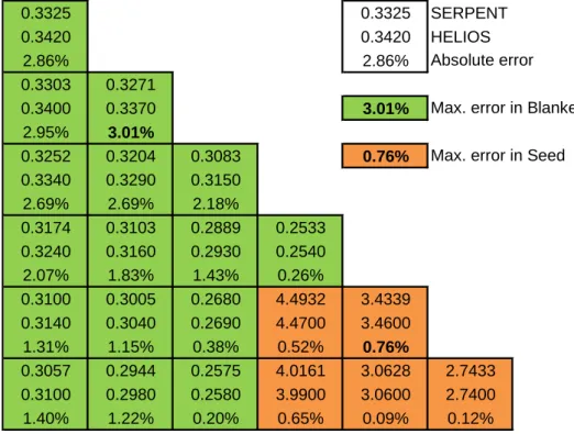
The results of the 11×11 SB fuel assembly benchmark calculations are presented in Fig. 2.3 – Fig.2.5. The discrepancy in k-inf is about 0.35% at BOL, and drops to less than 0.15% at end of life (EOL) as shown in Fig. 2.3.b. The maximum difference in the FIR is about 0.2% and was observed at the EOL (Fig. 2.3.b). The differences in isotopic concentration presented for Th232 and U233 in Fig 2.4.c is lower than 0.01%
and 0.25%, respectively, over the whole burnup. In case of Pa233, the maximum discrepancy is notably higher and reaches 2% (Fig. 2.4.c). This difference can be partially explained by its relatively low concentration in the fuel, as shown in Fig.
2.4.a. The BOL pin power distribution calculated by Serpent and HELIOS is presented in Fig 2.5. In the seed region hosting most of the initial fissile material the maximum deviation is about 0.8%. Somewhat higher maximum discrepancy of about 3% was observed in the low power blanket region.
The HELIOS results show generally good agreement when compared against the SERPENT code. Therefore, it can be concluded that HELIOS is a suitable tool for the analysis of heterogeneous Th-U233 fuel assembly configurations.
Based on the results, the HELIOS model was adjusted for the next studies as follows: resonance category RES = 6, coupling k = 4, and pin-cell nodalization according to Fig. 2.2.a, which means eight azimuthal regions in the moderator zone, one radial region in cladding, and two radial regions in fuel.
a. K-inf and FIR as a function of burnup, HELIOS
b. Relative difference in k-inf and FIR as a function of burnup Fig. 2.3. Comparison of k-inf and FIR, HELIOS vs. SERPENT
a. Concentration of U233 and Pa233 as a function of burnup
b. Concentration of Th232 as a function of burnup
c. Relative difference in actinide concentration as a function of burnup Fig. 2.4. Comparison of actinide concentration, HELIOS vs. SERPENT
Fig. 2.5. Pin-by-pin power distribution for 1/8th FA at 0 MWd/kg
2.2 3D level analysis tools
The 3D full core analysis was performed using the nodal diffusion code DYN3D (Grundmann et al., 2000) developed for 3D steady state and transient core calculations in square and hexagonal fuel element geometry with thermal-hydraulic (T-H) feedback. The DYN3D code is also capable of performing burnup calculation.
The neutronic kinetic model is based on the solution of time dependent 3D multi- group diffusion equation using nodal expansion method. The two-phase T-H module is based on the solution of four differential balance equations for mass, energy and momentum of the two-phase mixture and the mass balance for the vapor phase in parallel coolant channels. A scheme of the DYN3D is shown in Fig. 2.6.
DYN3D is a best estimate code and is also one of the reference 3D core simulators within a European simulation platform for nuclear reactor safety – NURESIM (Chauliac et al., 2011). The DYN3D code was extensively verified and validated via numerous numerical and experimental benchmark problems. For example the DYN3D code was applied in NEA CRP benchmarks for PWR and BWR (Grundmann and Rohde, 1996), the Three-Miles-Island-1 main steam line break and the Peach Bottom Turbine Trip benchmarks (Grundmann and Kliem, 2003;
Grundmann al., 2004), and others (Rohde et al., 2009). Results of verification and
0.3325 0.3325 SERPENT
0.3420 0.3420 HELIOS
2.86% 2.86%
0.3303 0.3271
0.3400 0.3370 3.01%
2.95% 3.01%
0.3252 0.3204 0.3083 0.76%
0.3340 0.3290 0.3150 2.69% 2.69% 2.18%
0.3174 0.3103 0.2889 0.2533 0.3240 0.3160 0.2930 0.2540 2.07% 1.83% 1.43% 0.26%
0.3100 0.3005 0.2680 4.4932 3.4339 0.3140 0.3040 0.2690 4.4700 3.4600
1.31% 1.15% 0.38% 0.52% 0.76%
0.3057 0.2944 0.2575 4.0161 3.0628 2.7433 0.3100 0.2980 0.2580 3.9900 3.0600 2.7400
1.40% 1.22% 0.20% 0.65% 0.09% 0.12%
Max. error in Blanket Max. error in Seed Absolute error
validation activities demonstrated that DYN3D is an effective tool for steady-state and transient core analyses.
Fig. 2.6. DYN3D structure
Chapter 3. Assembly level analysis
This chapter presents the results of the assembly-level parametric study aiming at the selection of a number of SB fuel assembly configurations for the following whole- core analysis. The assembly configurations are selected according to their potential to satisfy the specified fuel cycle requirements and comply with the T-H safety limits.
3.1 Calculation methodology
This sub-section refers to the calculation methodology of the neutronic parameters that were used during the neutronic optimization, and of the T-H parameters used for the final nomination of optimized SB fuel assembly configurations.
3.1.1 Neutronic analysis
As previously mentioned, all neutronic and burnup calculations on 2D assembly level were performed with the HELIOS code. The results of single assembly burnup calculations were used to estimate the behavior of a full core by applying Non-Linear Reactivity Model (NLRM) (Driscoll et al., 1990; Fridman et al., 2007). The NLRM is typically used for approximate calculation of discharged burnup, reactivity, and fuel cycle length of cores loaded with advanced fuels having non-linear dependence of reactivity on burnup. In such cases, the calculated reactivity data versus burnup are interpolated by a polynomial. NLRM assumes equal power share between the fuel batches in the core. Therefore, the core reactivity is calculated as an average of the reactivity values of each fuel batch corrected for leakage. The leakage reactivity worth of 2% was used in the NLRM. This value was estimated from a simplified full core analysis.
In this study, the 3rd order polynomial was used to fit the reactivity versus burnup data, and the reactivity was calculated according to following expression:
3 3 2 2 1
0+A ×BU+A ×BU +A ×BU
A
=
(BU) (3.1)
where represents the reactivity and BU the burnup. The expansion coefficients Ai ( i=0,..,3 ) were obtained with a help of the MATLAB function polyfit. We assumed the equal power sharing between all fuel batches within the core, and we set the average core reactivity corrected for leakage (ρleakage) to zero at the end of cycle (EOC). The
burnup accumulated by each batch in one cycle (BUC) can be calculated from the following equation:
0 3 -
) BU
× (3 + ) BU
× (2 + )
= (BU
(EOC) C C C leakage
core
(3.2)
where the discharged burnup is equal to EOC burnup of the last batch in our case 3rd batch, accordingly;
C DISCH
BU
× 3
=
BU (3.3)
The conversion performance of SB fuel assemblies was assessed by evaluating the FIR at EOL. The FIR, calculated as a ratio of instantaneous to initial fissile nuclide inventory, estimates the Th232 to U233 conversion performance and therefore serves as the main feasibility criterion of the HC fuel cycle. In FIR calculations, the instantaneous fissile inventory also included Pa233 due to its relatively fast conversion into U233 through the β-decay with the half-life of about 27 days.
Inventory Nuclides
Fissile Initial
(t) at time Inventory
Nuclides Fissile
=
FIR (3.4)
The neutronic calculations for the reference SB fuel assembly were performed assuming reduced core average power densities of 70 W/cc. This value was adopted as an initial guess from the previous T-H study (Volaski et al., 2009) performed on a single fuel assembly channel level. However, it must be mentioned that the study analyzed somewhat different assembly with reduced radial dimensions, duplex seed pins and ThH2 blanket fuel. Moreover, the core radial power profile was not taken into account in the analysis. Therefore, further reduction in the power density level down to 55 W/cc was considered in the parametric neutronic and T-H calculations.
3.1.2 T-H analysis
The T-H behavior of the SB fuel assemblies was analyzed using T-H module of DYN3D. At this stage, the calculations were performed with a given power for a single 3D fuel assembly. Every fuel pin was modeled as a separate T-H channel. The 3D power distribution was calculated as a product of the pin-wise radial power profile obtained from HELIOS simulations, core axial power distribution, core radial power
peak, and finally, the average power density in question. Chopped cosine shape axial power profile was used in the analysis. The maximum core radial power peak was assumed to be equal to 1.3.
The objective of this simplified T-H analysis was to select the SB fuel assembly configurations for the full core analysis through an evaluation of following T-H parameters: center line fuel temperature (TCL), Departure from Nucleate Boiling Ratio (DNBR), and void fraction.
The TCL refers to the highest temperature occurring at the central line of the solid fuel and it is an important indicator of fuel melting which should be avoided at all normal operating conditions and during design base accidents.
The void fraction is defined as fraction of channel volume that is occupied by the gas phase. Although there is no any exact limit for the void fraction, the only sub- cooled boiling can be accepted. The sub-cooled boiling occurs when the surface temperature is higher than the temperature of the saturated fluid. The location where the vapour can exist in a stable state on the heated surface without condensing is designated as the Onset of Nucleate boiling (ONB).
Departure from Nucleate Boiling (DNB) describes the phenomenon of transition from nucleate to film boiling which occurs when the heat flux reaches some critical value. Critical heat flux (CHF) is the heat flux at which the vapour film around a heated surface is formed and, subsequently, boiling crisis takes place. The vapour film, reducing the surface-to-coolant heat transfer, causes prompt increase in the fuel rod surface temperature and, consequently, a failure of the cladding material.
The DYN3D code calculates directly DNBR as a ratio of the CHF and a local heat flux by using one of the correlations IAE-4 (Osmachkin, 1978), OKB-2 (Bezrukov et al., 1976), Pernica (Pernica and Čižek, 1992) or BIASI (Biasi et al., 1967). In this work, DNBR values were obtained using the Pernica CHF model. It is based on approximately 18,000 experimental data points in about 350 test geometries with both relatively wide and very tight rod lattices. The range of validity of Pernica CHF model with respect to pressure (p), coolant mass flux (G), steam quality (x), and pitch-to-diameter (P/D) ratio is 0.26 < p < 18.7 MPa, 34 < G < 7500 kg/m2s, -0.49 <x
< 0.99, and 1.02 < s < 2.48. The P/D ratios for seed and blanket lattices are equal to 1.326 and 1.023 respectively. Since these values are within the validity range of Pernica model, it appears to be applicable to CHF prediction in SB fuel assemblies.
The thermal conductivity of ThO2 base fuel is higher than that of UO2 base fuel over most of the temperature range of interest (Belle and Berman, 1984); however, the ThO2-UO2 mixture has the thermal conductivity comparable with that of the pure UO2. Therefore, in this study, the thermal conductivity of ThO2-UO2 mixture was conservatively presumed to be equal to that of UO2.
3.2 Description of the reference HC Th-U233 SB PWR fuel assembly
One of the main design goals in the development of HC SB fuel assembly is to maximize FIR, while meeting fuel cycle and safety requirements. The optimization of SB assembly design is a complex multi-objective problem, which involves many independent parameters (e.g. fuel pin cell and fuel assembly lattice pitch dimensions, number of seed and blanket fuel rods, their radial dimensions, fissile content in seed and blanket, average power density, etc.). Performing the full scale optimization is very computationally expensive, iterative procedure, requiring a large number of 2D fuel lattice and 3D full core calculations. It should be stressed that the selected reference SB design is not the optimized one, but rather one of the several possible configurations. It was developed by fixing some of the independent parameters as well as by taking the previous experience into account. This section presents the reference SB fuel assembly design and explains rationale behind the selection of the main operating parameters.
In this study, a large Westinghouse PWR core with available operating data (Galperin et al., 1995) was selected as a reference for investigation into the operational performance of HC Th-U233 fuel. The summary of the main operating parameters of the reference PWR is presented in Table 3.1.
The SB fuel assembly is required to be directly retrofittable into the reference PWR without introducing any major changes into the core and plant design. For that reason, the proposed SB fuel assembly has standard outer dimensions, a typical 17×17 pin lattice and 25 guide tubes at the usual locations.
A target fuel cycle length was fixed to twelve months assuming 3-batch reloading scheme and a capacity factor of 90%. This is equivalent to the fuel cycle length of 330 effective full power days (EFPD). The relatively short fuel cycle was considered because of the degradation of FIR with burnup as observed in the previous study (Shwageraus et al., 2009).
Table 3.1: Reference PWR core: summary of the main design parameters
Total thermal output, MW 3358
Number of fuel assemblies 193 Average core power density, W/cc 104.0
System pressure, bar 155
Total core flow rate, kg/s 17456 Core inlet temperature, ºC 265.5
Active fuel height, cm 366
Assembly array 17 17
Number of fuel rods per assembly 264
Assembly pitch, cm 21.5
Fuel rod pitch, cm 1.26
Fuel pellet radius, cm 0.4095
Cladding outer radius, cm 0.4750
Cladding material Zircaloy
Number of guide tubes 25
Guide tube inner radius, cm 0.5715 Guide tube outer radius, cm 0.6120
Earlier studies suggested using Th hydride as a blanket fuel form because the presence of hydrogen in the fuel promotes neutron captures in Th. However, softer spectrum also increases the burnup rate of generated U233, resulting, on the overall balance, in lower FIR at the EOL. Therefore, in this study, an oxide fuel form was selected also because of the substantial experience accumulated with thoria in the past. As mentioned earlier, the transition from homogeneous to heterogeneous fuel assembly layout is a crucial condition for achieving high conversion. Therefore, the fuel assembly was subdivided into the two rectangular seed and blanket regions. Most of the U233 is concentrated in the central 9×9 seed, while remaining 191 fuel pins, with significantly lower than in seed U233 content, form the blanket region. The number of the pins in the regions was selected to approximately preserve the seed to blanket volumetric ratio close to that of the optimized SB design reported in (Shwageraus et al., 2009). It is worth mentioning that the square seed region configuration may be not the optimal one from a neutronics point of view, as was shown in (Kotlyar and Shwageraus, 2012). Nevertheless, the square layout was selected to enable subsequent 3D full core analysis with the nodal diffusion DYN3D
code, which is only capable of modeling reactor cores with regular square or rectangular mesh.
While the seed fuel pins have typical PWR dimensions, the blanket fuel pin radius was enlarged in order to enhance the conversion performance of the SB fuel assembly. In order to demonstrate the effect of the blanket pin radius on FIR, two burnup calculations were performed with the blanket pin radius increased from 0.4095 cm (i.e. typical PWR value) to 0.5300 cm. In both cases, the U233 content in the seed was adjusted to achieve the target fuel cycle length of 330 EFPD. Fig. 3.1 shows that an increase in blanket radius results in higher FIR during the entire irradiation period.
The burnup depended concentration of U233 for both cases is presented in Fig 3.2 showing somewhat steeper U233 generation rate in the blanket with enlarged radius.
This increase in FIR is a trade-off between two effects. On the one hand, the increase in blanket dimensions reduces the moderation, hardens the neutron spectrum, and decreases effective σa of Th232 in the blanket (Table 3.2). On the other hand, the total absorption rate in the blanket Th232 increases with the radius (Table 3.2). This is because larger blanket pins have significantly higher volume and, consequently, higher Th232 mass.
Fig. 3.1. FIR vs. burnup, variable blanket pin radius
a. Blanket radius = 0.4095 cm
b. Blanket radius = 0.5300 cm
Fig. 3.2. U233 mass vs. burnup, variable blanket pin radius
Table 3.2: Th232 in blanket: one-group σa and absorption reaction rates
Blanket pin radius, cm 0.4095 0.5300 Blanket pin volume (V), cm3 192.8 323.0
σa, barn 1.58 1.01
Σa∙φ, 1/cm3∙s 3.91E+14 2.65E+14 Σa∙φ∙V, 1/s 7.54E+16 8.56E+16
An additional series of burnup calculations was performed with the blanket U233 content varying from 2.33 to 0.25 w/o. In every case, the seed U233 content was modified to preserve the target fuel cycle length. Reducing the blanket U233 content decreases the reactivity swing (Fig. 3.3) and improves the FIR (Fig. 3.4). However, reducing the blanket U233 content below 0.5 w/o may lead to sub-critical core (Fig.
3.3). Therefore, starting from this point, the blanket U233 content was fixed at 0.5 w/o.
Fig. 3.5 shows the seed-blanket power share as a function of burnup for the case with 9.55 and 0.5 w/o U233 content in seed and blanket, respectively. The power imbalance at BOL can be clearly observed while the seed is generating about 75% of the power in the assembly. The power imbalance between seed and blanket reduces with burnup and diminishes entirely towards the EOL.
Fig. 3.3. Core reactivity vs. burnup, variable seed and blanket U233 content
Fig. 3.4. Fuel Assembly FIR vs. burnup, variable seed and blanket U233 content
Fig. 3.5. Power share between seed and blanket vs. burnup
The reference SB fuel assembly is presented schematically in Fig 3.6. Summary of the main assembly design parameters is given in Table 3.3.
Fig. 3.6. Reference SB fuel assembly: radial layout
Table 3.3: Reference SB fuel assembly: summary of the main design parameters
Pin pitch, cm 1.26
Seed fuel pellet radius, cm 0.4095 Seed cladding outer radius, cm 0.4750 Blanket fuel pellet radius, cm 0.5300 Blanket cladding outer radius, cm 0.6155 Guide tube inner radius, cm 0.5715 Guide tube outer radius, cm 0.6120 Seed/Blanket fuel material U233O2-ThO2
U233 content in blanket, w/o 0.5
Number of seed pins 72
Number of blanket pins 192
Number of guide tubes 25
3.3 Parametric neutronic and T-H calculations
This section reports on the selection of SB configurations for the following 3D full core analysis. The task was accomplished using the following two-step procedure.
At the first stage, depletion analysis of the SB assembly was performed assuming different core average power densities of 55, 60, 65, and 70 W/cc. The reference PWR core has somewhat lower than typical coolant inlet temperature (Tin) of 265.5 °C (Table 3.1). Therefore, two additional inlet coolant temperature values of 275.0, and 289.0 °C were considered in the analysis and calculations were performed using average coolant temperatures (Tave) of 280.0, 290.0, and 310.0 °C approximately corresponding to the inlet coolant temperatures mentioned above. For every combination of average power density and Tave, the fissile content was adjusted to achieve the target fuel cycle length of 330 EFPD.
At the next stage, 3D single assembly T-H analysis of all aforementioned cases was performed in order to determine the most promising combinations of power density level and Tin at which the safety limits are not exceeded. The following limiting T-H criteria were specified:
- Maximum acceptable TCL was set to 3100°C which is 200°C below the melting point of the Th-U oxide (Belle and Berman, 1984).
- Minimum DNBR (MDNBR) must be at least 1.3, which is a limit typically used in the PWR thermal analysis.
- The maximum temperature of the coolant bulk should be below saturation temperature allowing for a limited sub-cooled boiling only.
As described in Section 3.2, blanket fuel pins are enlarged as compared to seed fuel pins. Consequently, blanket lattice has somewhat higher flow resistance as compared to the standard UO2 and seed fuel pins resulting in a higher overall pressure drop over the active core, Δp. Since pumping power is proportional to Δp and the volumetric flow rate ( ̇), preserving the reference flow rate will lead to increase in pumping power and will require the uprate of the primary coolant pumps. In order to avoid any significant modifications of the plant infrastructure, it was decided to preserve the pumping power of the Th-U233 core equal to that of the reference PWR core by adjusting the total coolant mass flow rate ( ̇).
The results of depletion calculations are summarized in Table 3.4. In all cases, FIR values close to unity were observed. Increasing the average coolant temperature