Hierarchical Hybrid Modeling of Embedded Systems
?R. Alur, T. Dang, J. Esposito, R. Fierro, Y. Hur, F. Ivancic, V. Kumar, I. Lee, P. Mishra, G. Pappas, and O. Sokolsky
University of Pennsylvania http://www.seas.upenn.edu/hybrid/
Abstract.
This paper describes the modeling language
Charonfor modular design of interacting hybrid systems. The language allows spec- ication of architectural as well as behavioral hierarchy, and discrete as well as continuous activities. The modular structure of the language is not merely syntactic, but is exploited by analysis tools, and is supported by a formal semantics with an accompanying compositional theory of renement. We illustrate the benets of
Charonin design of embedded control software using examples from automated highways concerning vehicle coordination.
1 Introduction
An embedded system typically consists of a collection of digital programs that interact with each other and with an analog environment. Examples of embed- ded systems include manufacturing controllers, automotive controllers, engine controllers, avionic systems, medical devices, micro-electromechanical systems, and robots. As computing tasks performed by embedded devices become more sophisticated, the need for a sound discipline for writing embedded software be- comes more apparent (c.f [23]). Model-based design paradigm, with its promise for greater design automation and formal guarantees of reliability, is particularly attractive given the following trends.
Software Design Notations. Modern object-oriented design paradigms such as Unied Modeling Language (UML) allow specication of the architec- ture and control at high levels of abstraction in a modular fashion, and bear great promise as a solution to managing the complexity at all stages of the software design cycle [7]. There are emerging tools such as RationalRose (see
www.rational.com ) that support modeling, simulation, and code generation, and are increasingly becoming popular in domains such as automotive software and avionics.
Control Engineering. Traditionally control engineers have used tools for continuous dierential equations such as Matlab (see www.mathworks.com ) for modeling of the plant behavior, for deriving and optimizing control laws, and for validating functionality and performance of the model through analysis and
?
Supported by DARPA MoBIES grant F33615-00-C-1707
simulation. Tools such as Simulink recently augmented the continuous modeling with state-machine-based modeling of discrete control.
Formal Verication Tools. Model checking is emerging as an eective technique for debugging of high-level models (see [10] for a survey). Model check- ers such as SMV [26] and SPIN [20] have been successful in revealing subtle errors in cache coherency protocols in multiprocessors and communication protocols in computer networks. In recent years, the model checking paradigm has been suc- cessfully extended to models with continuous variables leading to tools such as UPPAAL [22], HyTech [18], and CheckMate [8].
This paper describes our modeling language, Charon , that is suitable for high-level specication of interacting embedded systems. We proceed to discuss the three distinguishing aspects of Charon .
Hybrid Modeling. Traditionally, control theory and related engineering disciplines, have addressed the problem of designing robust control laws to en- sure optimal performance of processes with continuous dynamics. This approach to system design largely ignores the problem of implementing control laws as a piece of software and issues related to concurrency and communication. Com- puter science and software engineering, on the other hand, have an entirely discrete view of the world, which abstracts from the physical characteristics of the environment to which the software is reacting to, and is typically unable to guarantee safety and/or performance of the embedded device as a whole. An embedded system consisting of sensors, actuators, plant, and control software is best viewed as a hybrid system. The relevance of hybrid modeling has been demonstrated in various applications such as coordinating robot systems [2], automobiles [6], aircrafts [29], and chemical process control systems [13].
Early formal models for hybrid systems include phase transition systems [25]
and hybrid automata [1]. While modularity in hybrid specications has been addressed in languages such as hybrid I/O automata [24], Charon allows richer specications. Discrete updates in Charon are specied by guarded actions la- beling transitions connecting the modes. Some of the variables in Charon can be declared analog, and they ow continuously during continuous updates that model passage of time. The evolution of analog variables can be constrained in three ways: dierential constraints (e.g. by equations such as _
x=
f(
x;u)), al- gebraic constraints (e.g. by equations such as
y=
g(
x;u)), and invariants (e.g.
jx,yj"
) which limit the allowed durations of ows.
Hierarchical Modeling. Modern software design paradigms promote hi-
erarchy as one of the key constructs for structuring complex specications. We
are concerned with two distinct notions of hierarchy. In architectural hierarchy,
a system with a collection of communicating agents is constructed by parallel
composition of atomic agents, and in behavioral hierarchy, the behavior of an
individual agent is described by hierarchical sequential composition. The for-
mer hierarchy is present in almost all concurrency formalisms, and the latter,
while present in all block-structured programming languages, was introduced for
state-machine-based modeling in Statecharts [17].
In Charon , the building block for describing the system architecture is an agent that communicates with its environment via shared variables. The lan- guage supports the operations of composition of agents to model concurrency, hiding of variables to restrict sharing of information, and instantiation of agents to support reuse. The building block for describing ow of control inside an atomic agent is a mode. A mode is basically a hierarchical state machine, that is, a mode can have submodes and transitions connecting them. Variables can be declared locally inside any mode with standard scoping rules for visibility. Modes can be connected to each other only via well-dened entry and exit points. We allow sharing of modes so that the same mode denition can be instantiated in multiple contexts. To support exceptions, the language allows group transitions from default exit points that are applicable to all enclosing modes, and to sup- port history retention, the language allows default entry transitions that restore the local state within a mode from the most recent exit.
Compositional Semantics. Formal semantics leads to denitions of seman- tic equivalence (or renement) of specications based on their observable behav- iors, and compositional means that semantics of a component can be constructed from the semantics of its subcomponents. Such formal compositional semantics is a cornerstone of concurrency frameworks such as CSP [19] and CCS [27], and is a prerequisite for developing modular reasoning principles such as compositional model checking and systematic design principles such as stepwise renement.
The global nature of time makes it challenging to dene semantics of hybrid components in a modular fashion. For rich hierarchical specications, features such as as group transitions, exceptions, and history retention, cause additional diculties.
Charon supports observational trace semantics for both modes and agents [4].
The key result is that the set of traces of a mode can be constructed from the traces of its submodes. This result leads to a compositional notion of renement for modes. Suppose we obtain an implementation design
Ifrom a specication design
Ssimply by locally replacing some submode
Nin
Sby a submode
M. Then, to show
Irenes
S, it suces to show that
Mrenes
N.
Overview. The remaining paper is organized as follows. In Section 2, we present the features of the language Charon , and in Section 3 we describe the formal semantics and accompanying compositional renement calculus. We use examples from the automotive experimental platform of the DARPA's Mo- BIES program for illustrative purposes. Section 4 gives a summary of the design toolkit, and we conclude in Section 5 with pointers to ongoing research on formal analysis.
2 Modeling Language
2.1 Agents and Architectural Hierarchy
We present an example from the MoBIES Automotive Open Experimental Plat-
form (OEP) to illustrate the features of Charon . Figures 1, 2, and 3 are Charon
agent diagrams illustrating the architectural hierarchy of a team of two vehicles.
Vehicle
accOut velOut accIn velIn
(a)
VehicleFollower
fA fV lA lV VehicleLeader
VehicleSystem
lV lA
(b)
Fig.1.
The Leader-Follower Vehicle System
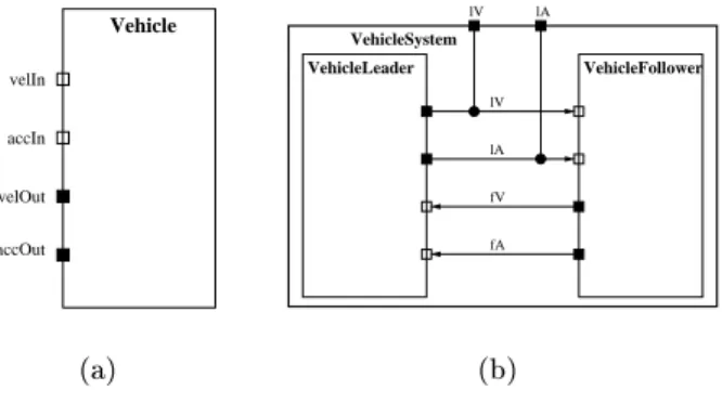
A single vehicle is represented by the agent V ehicle, shown in Figure 1(a).
Each agent has a well-dened interface which consists of its typed input and output variables. In the case of V ehicle, velIn and accIn are the input variables, and velOut and accOut are the outputs. Formally, an agent consists of a set of variables
V, a set of initial states, and a set of modes
TM. The set
Vis partitioned into local variables
Vland global variables
Vg; global variables are further partitioned into input and output variables. Type correct assignments of values to variables are called valuations and denoted
QV. The set of initial states
I Q
V
species possible initializations of the variables of the agent. The modes, described in more detail below, collectively dene the behavior of the agent. An atomic agent has a single top-level mode. Composite agents have many top-level modes and are constructed from other agents as described below.
Figure 1(b) illustrates the three operations dened on agents. It shows a com- posite agent VehicleSystem that contains two instances of the agent Vehicle composed in parallel. The parallel agents execute concurrently and communi- cate through shared variables. To enable communication between the two vehi- cles, global variables are renamed. For example, velIn of the follower agent and
velOut of the leader agent are both renamed to lV . Finally, the communication between the vehicles can be hidden from the outside world. In our example, only the leader's outputs lV and lA are the outputs of the composite system. The composite agent is written in Charon syntax as below:
1agent VehicleSystem { write analog real lV, lA;
private analog real fV, fA;
agent VehicleLeader= Vehicle[velIn,velOut,accIn,accOut := fV,lV,fA,lA];
agent VehicleFollower= Vehicle[velIn,velOut,accIn,accOut := lV,fV,lA,fA];}
1
Charon
also allows parameterized denitions. For instance, the initial position of the
vehicle can be dened as a parameter within the agent Vehicle , and can be assigned
to dierent values in the two instances VehicleLeader and VehicleFollower .
VehiclePlant
xDot_hslCarSensor RegulationController
Vehicle
xDDot_hsl
u_isl
xDDot
xDot
velIn
accIn
velOut
accOut
xDDot: plant acceleration u_isl: desired acceleration xDot_hsl: sensed plant velocity xDDot_hsl: sensed plant acceleration xDot: plant velocity
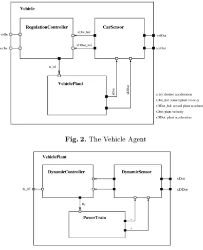
Fig.2.
The Vehicle Agent
DynamicSensor DynamicController
VehiclePlant
u_isl xDDot
xDot
ud
PowerTrain
va
Fig.3.
The VehiclePlant Agent
The agent Vehicle itself has a hierarchical structure. Figure 2 illustrates the overall vehicle architecture, which comprises the regulation controller, the car sensor, and the vehicle plant. The higher level regulation controller handles data from the car sensor or other vehicles and generates a desired acceleration to the vehicle plant. The lower level dynamics controller equipped in the vehicle plant controls actual vehicle dynamics such as throttling and braking. The ve- hicle plant is composed of the dynamic controller, the dynamic sensor, and the powertrain. Figure 3 describes the vehicle plant. The dynamic controller maps the control command u onto a desired throttle position or brake command u d . The sign of u d will dene two submodes of the powertrain: acceleration and brake. We show how the behavior of an agent is modeled in the next section.
2.2 Modes and Behavioral Hierarchy
Modes represent behavioral hierarchy in the system design. The behavior of each
atomic agent is described by a mode, which corresponds to a single thread of
read analog real ud;
write analog real v, a;
{a == k1*(ud-k2*v*v -k3*Math.sin(theta)-k4)}
alge algeAcceleration diff diffVelocity {d(v) == a}
Fig.4.
The Behavior of the Agent PowerTrain
BrakeNormal
ThrottleNormal BrakeSaturated
ThrottleSaturated
{u 0 } d {u < 0 }d inv d
inv u < 0
u 0d
dx
dx
ThrottleControl de
BrakeControl
dx dx
dx
dx
de
de
de
u 0d init
u < 0d
≥
≥
≥
DynamicController
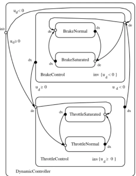
Fig.5.
The Behavior of the Agent DynamicController
control. At the lowest level of the behavioral hierarchy are atomic modes. They describe continuous behaviors. For example, Figure 4 illustrates the behavior of the agent PowerTrain . There is a dierential constraint diffVelocity that asserts the relationship between velocity
vand acceleration
a: _
v=
a, and an algebraic constraint algeAcceleration for the acceleration, relating it to the current speed
v, the control input
ud, and the road grade
:
a=
k1(
ud,k2v 2
,k
3
sin(
)
,k4) for some constants
k1;:::;k4.
Composite modes contain a number of submodes. During execution, a com- posite mode performs discrete transitions, switching between its submodes. Each (sub)mode has a well-dened data interface consisting of typed global variables used for sharing state information, and also a well-dened control interface con- sisting of entry and exit points that are used to connect modes modes via tran- sitions. For example, the behavior of the agent DynamicController is captured by the mode shown in Figure 5. Depending on the sign of the input variable
udthat represents the acceleration desired by the higher-level controller, the dy- namic controller applies either brake or throttle, represented by the submodes
BrakeControl and ThrottleControl , respectively. The condition for staying in
the ThrottleControl mode is captured by the invariant
ud0. When the sign
of
udchanges to negative, the invariant is violated and the controller is forced to take a transition to BrakeControl . Note that the mode ThrottleControl
also has internal structure: acceleration may be normal, when a larger desired acceleration translates in more torque supplied by the engine, or saturated, when the limit of the engine capacity has been reached. The transition from
ThrottleControl to BrakeControl happens regardless of which submode of
ThrottleControl was active at that time, interrupting any lower-level behav- iors.
Formally, a mode
Mconsists of a set of submodes
SM, a set of variables
V, a set of entry control points
E, a set of exit control points
X, a set of transitions
T
, and a set of constraints
Cons. As in agents, variables are partitioned into global and local variables. For the submodes of
M, we require that each global variable of a submode is a variable (either global or local) of
M. This induces a natural scoping rule for variables in a hierarchy of modes: a variable introduced as local in a mode is accessible in all its submodes but not in any other mode.
Every mode has two distinguished control points, called default entry (
de) and exit (
dx) points. They are used to represent such high-level behavioral notions as interrupts and exceptions, which will be discussed in more detail in the following section.
The set Cons of constraints contains constraints of three kinds. An invariant species when a mode can be active. Continuous trajectories of a variable
xcan be given by either an algebraic constraint
Ax, which denes the set of admissible values for
xin terms of values of other variables, or by a dierential constraint
D
x
, which denes the admissible variables for the rst derivative of
xwith respect to time.
Transitions of a mode
Mcan be classied into entry transitions, which con- nect an entry point of
Mwith an entry point of one of its submodes, exit transi- tions, connecting exit points of submodes to exit points of
M, and internal tran- sitions that lead from an exit point of a submode to an entry point of another submode. Every transition has a guard, which is a predicate over the valuations of mode variables that tells when the transition can be executed. When a transi- tion occurs, it executes a sequence of assignments, changing values of the mode variables. A transition that originates at a default exit point of a submode is called a group transition of that submode. A group transition can be executed to interrupt the execution of the submode.
In Charon , transitions and constraints can refer to externally dened Java classes, thus allowing rich discrete and continuous specications.
3 Formal Semantics and Compositional Renement
We proceed to dene a compositional formal semantics for Charon . First, the
operational semantics of modes and agents makes the notion of executing a
Charon model precise, and can be used, say, by a simulator. Second, we dene
an observational semantics for modes and agents. The observational semantics
hides the details about internal structure, and retains only the information about
inputs and outputs. Informally, the observational semantics consists of the static interface (such as the global variables and entry/exit points) and dynamic in- terface consisting of the traces, that is, sequences of updates to global variables.
Third, for modularity, we show that our semantics is compositional. This means that the set of traces of a component can be dened from the set of traces of its subcomponents. Intuitively, this means that the observational semantics cap- tures all the information that is needed to determine how a component interacts with its environment. Finally, we dene a notion of renement (or equivalence) for modes/agents. This allows us, for instance, to relate dierent models of the agent PowerTrain . We can establish that the abstract (simplied) version of powertrain renes the detailed version, and then, to analyze the system of ve- hicles, use the abstract version instead of the detailed one. The compositional rules about renement form the basis for analysis in a system with multiple components, each with a simplied and a detailed model.
3.1 Formal semantics of modes
Intuitive semantics. Before presenting the semantics formally, we give the intuition for mode executions. A mode can engage in discrete or continuous be- havior. During an execution, the mode and its environment either take turns making discrete steps or take a continuous step together. Discrete and continu- ous steps of the mode alternate. During a continuous step, the mode follows a continuous trajectory that satises the constraints of the mode. In addition, the set of possible trajectories may be restricted by the environment of the mode.
In particular, when the mode invariant is violated, the mode must terminate its continuous step and take one of its outgoing transitions. A discrete step of the mode is a nite sequence of discrete steps of the submodes and enabled transi- tions of the mode itself. A discrete step begins in the current state of the mode and ends when it reaches an exit point or when the mode decides to yield con- trol to the environment and lets it make the choice of the next step. Technically, when the mode ends its discrete step in one of its submodes, it returns control to the environment via its default exit point. The closure construction, described below, ensures that the mode can yield control at appropriate moments, and that the discrete control state of the mode is restored when the environment schedules the next discrete step.
Preemption. An execution of a mode can be preempted by a group tran- sition. A group transition of a mode originates at the default exit of the mode.
During any discrete step of the mode, control can be transferred to the default exit and an enabled group transition can be selected. There is no priority be- tween the transitions of a mode and its group transitions. When an execution of a mode is preempted, the control state of the mode is recorded in a special history variable, a new local variable that we introduce into every mode. Then, when the mode is entered through the default entry point next time, the control state of the mode is restored according to the history variable.
The history variable and active submodes. In order to record the
location of discrete control during executions, we introduce a new local variable
h
into each mode that has submodes. The history variable
hof a mode
Mhas the names of the submodes of
Mas values, or a special value
that is used to denote that the mode does not have control. A submode
Nof
Mis called active when the history variable of
Mhas the value
N.
Flows. To precisely dene continuous trajectories of a mode, we introduce the notion of a ow. A ow for a set
Vof variables is a dierentiable function
f
from a closed interval of non-negative reals [0
;] to
QV. We refer to
as the duration of the ow. We denote a set of ows for
Vas
FV.
Syntactic restrictions on modes. In order to ensure that the semantics of a mode is well-dened, we impose several restrictions on mode structure. First, we assume that the set of dierential and algebraic constraints in a mode always has a non-empty set of ows that satisfy them. This is needed to ensure that the set of behaviors of a mode is non-empty. Furthermore, we require that the mode cannot be blocked at any of its non-default control points. This means that the disjunction of all guards originating from a control point evaluates to true .
State of a mode. We dene the state of a mode in terms of all variables of the mode and its submodes, including the local variables on all levels. We use
Vfor the set of all variables. The set of local variables of a mode together with the local variables of the submodes are called the private variables and is denoted as
Vp.
The state of a mode
Mis a pair (
c;s), where
cis the location of discrete control in the mode and
s2QM:V. Whenever the mode has control, it resides in one of its control points, that is,
c2M:C. Given a state (
c;s) of
M, we refer to
cas the control state of
Mand to
sas the data state of
M.
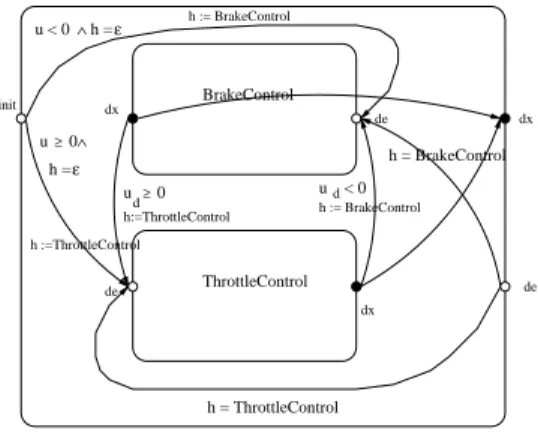
Closure of a mode. Closure construction is a technical device to allow the mode to interrupt its execution and to maintain its history variable. Transitions of the mode are modied to update the history variable
hafter a transition is executed. Each entry or internal transition assigns the name of the destination mode to
h, and exit transitions assign
to
h. In addition, default entry and exit transitions are added to the set of transitions of the mode. These default tran- sitions do not aect the history variable and allow us to interrupt an execution and then resume it later from the same point.
The default entry and exit transitions are added in the following way. For each submode
Nof
M, the closure adds a default exit transition from
N:dxto
M:dx
. This transition does not change any variables of the mode and is always enabled. Default entry transitions are used to restore the local control state of
M
. A default entry transition that leads from a default entry of
Mto the default entry of a submode
Nis enabled if
h=
N. Furthermore, we make sure that the default entry transitions do not interfere with regular entry transitions originat- ing from
de. The closure changes each such transition so that it is enabled only if
h=
. The closure construction for the mode DynamicController introduced in Section 2 is illustrated in Figure 6.
Operational semantics. An operational view of a closed mode
Mwith the set of variables
Vconsists of a continuous relation
RCand, for each pair
c12E,
c
2
2X
, a discrete relation
Rc1;c2D.
u < 0
dh =
h := BrakeControl init
dx de
BrakeControl
ε
h := BrakeControl
dx dx
d h:=ThrottleControl
u 0
h = ThrottleControl u < 0 h =
ThrottleControl
dede
ε
u 0
h :=ThrottleControl
h = BrakeControl
≥
∧
≥
∧
Fig.6.
Closed modes
The relation
RC QVFVgives, for every data state of the mode, the set of ows from this state. By denition, if the control state of the mode is not at
dx, the set of ows for the state is empty.
RCis obtained from the constraints of a mode and relations
SM:RCof its submodes. Given a data state
sof a mode
M, (
s;f)
2RCi
fsatises the constraints of
Mand, if
Nis the active submode at
s, (
s;f), restricted to the global variables of
N, belongs to
N:RC.
The relation
RDe;x, for each entry point
eand exit point
xof a mode, com- prises macro-steps of a mode starting at
eand ending at
x. A macro step con- sists of a sequence of micro-steps. Each micro-step is either a transition of the mode or a macro-step of one of its submodes. Given the relations
RDe;xof the submodes of
M, a micro-execution of a mode
Mis a sequence of the form (
e0;s0)
;(
e1;s1)
;:::;(
en;sn) such that every (
ei;si) is a state of
Mand for even
i
, ((
ei;si)
;(
ei+1;si+1)) is a transition of
M, while for odd
i, (
si;si+1) is a macro- step of one of the submodes of
M. Given such a micro execution of
Mwith
e
0
=
e2Eand
en=
x2X, we have (
s0;sn)
2Re;xD. To illustrate the notion of macro-steps, consider the closed mode DynamicController from Figure 6. Con- sidering only the control points, we have the following micro-execution when
u >
0 and
uc <maxThrottle: init, ThrottleNormal.de, ThrottleNormal.dx,
dx. For every
u;ucsatisfying the above inequalities this micro-execution gives us a macro-step in
Rinit;dxD.
The operational semantics of the mode
Mconsists of its control points
E[X
, its variables
Vand relations
RCand
RDe;x. The operational semantics of a mode denes a transition system
Rover the states of the mode. We write (
e1;s1)
!o(
e2;s2) if (
s1;s2)
2RDe1;e2, and (
dx;s1)
!f(
dx;s2) if (
s1;f)
2RC, where
f
is dened on the interval [0
;t] and
f(
t) =
s2. We extend
Rto include environ-
ment steps. An environment step begins at an exit point of the mode and ends
at an entry point. It represents changes to the global variables of the mode by
other components while the mode is inactive. Private variables of the mode are
unaected by environment steps. Thus there is an environment step (
x;s)
!"(
e;t)
whenever
x2X,
e2E, and
s[
Vp] =
t[
Vp]. We let
range over
FV [fo;"g. An
execution of a mode is now a path through the graph of
R: (
e0;s0)
!1(
e1;s1)
!2 ::: !n(
en;sn)
:Trace semantics. To be able to dene a renement relation between modes, we consider a trace semantics for modes. A trace of the mode is a projection of its executions onto the global variables of the mode. The trace semantics for
Mis given by its control points
Eand
X, its global variables
Vg, and its set of its traces
LM.
In dening compositional and hierarchical semantics, one has to decide, what details of the behavior of lower-level components are observable at higher levels.
In our approach, the eect of a discrete step that updates only local variables of a mode is not observable by its environment, but stoppage of time introduced by such a step is observable. For example, consider two systems, one of which is always idle, while the other updates a local variable every second. These two systems are dierent, since the second one does not have ows more than one second long. Dening a modular semantics in a way that such distinction is not made seems much more dicult.
3.2 Trace semantics for agents
An execution of an agent follows a trajectory, which starts in one of the initial states and is a sequence of ows interleaved with discrete updates to the variables of the agent. An execution of
Ais constructed from the relations
RCand
RDof its top-level mode. For a xed initial state
s0, each mode
M 2TMstarts out in the state (
initM;sM), where
initMis the non-default entry point of
Mand
s
0
[
M:V] =
sM. Note that as long as there is a mode
Mwhose control state is at
initM, no continuous steps are possible. However, any discrete step of such a mode will come from
RinitD M;dxand bring the control state of
Mto
dx. Therefore, any execution of an agent
A=
hTM;V;Iiwith
jTMj=
kwill start with exactly
k
discrete initialization steps. At that point, every top-level mode of
Awill be at its default exit point, allowing an alternation of continuous steps from
RCand discrete steps from
Rde;dxD. The choice of a continuous step involving all modes or a discrete step in one of the modes is left to the environment. Before each discrete step, there is an environment step, which takes the control point of the chosen mode from
dxto
deand leaves all the private variables of all top-level modes intact. After that, a discrete step of the chosen mode happens, bringing control back to
dx. Thus, an execution of
Awith
jTMj=
kis a sequence
s
0 o
!s
1 o
! :::s
k 1
!s
k +1 2
! :::
such that
{ The rst
ksteps are discrete and initialize the top-level modes of
A.
{ for every
ik, one of the following holds:
the
ithstep is a continuous step, in which every mode takes part, or
the
ithstep is a discrete environment step, or
the
ithstep is a discrete step by one of the modes and the private vari-
ables of all other modes are unchanged.
...
...
...
...
...
... < N
1...
M
k
M
k
M
11
M
1M
M M
C
1N
1
< N
1 k< N
k<
<
C M
1
M
kM
kC
2C
2Fig.7.
Compositionality rules for modes
Note that environment steps in agents and in modes are dierent. In an agent, an environment step may contain only discrete steps, since all agents participate in every continuous step. The environment of a mode can engage in a number of continuous steps while the mode is inactive.
A trace of an agent
Ais an execution of
A, projected onto the set of its global variables. The denotational semantics of an agent consists of its set of global variables
Vgand its set of traces
LA.
Trace semantics for modes and agents can be related to each other in an obvious way. Given an atomic agent
Awhose behavior is given by a mode
M, we can obtain a trace of
Aby taking a trace of
Mand erasing the information about the control points from it.
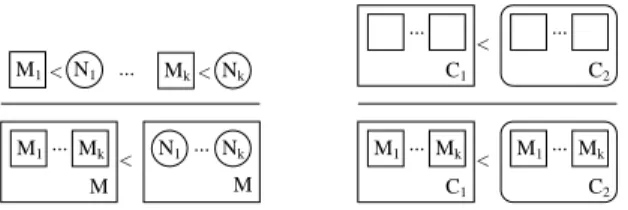
3.3 Compositionality results
We show that our semantics is compositional for both modes and agents. First, the set of traces of a mode can be computed from the denition of the mode itself and the semantics of its submodes. Second, the set of traces of a composite agent can be computed from the semantics of its sub-agents.
Mode Renement. The trace semantics leads to a natural notion of rene- ment between modes: a mode
Mrenes
Nif it has the same global variables and control points, and every trace of
Mis a trace of
N. A mode
Mand a mode
N
are said to be compatible if
M:Vg=
N:Vg,
M:E=
N:Eand
M:X=
N:X. Given two compatible modes
Mand
N,
Mrenes
N, denoted
MN, if
LMLN.
The renement operator is compositional with respect to the encapsulation.
If, for each submode
Niof
Mthere is a mode
Ni0such that
Ni Ni0, then we have that
M M0, where
M0is obtained from
Mby replacing every
Niwith
N 0
i
. The renement rule is explained visually in Figure 7, left.
A second renement rule is dened for contexts of modes. Informally, if we consider a submode
Nwithin a mode
M, the remaining submodes of
Mand the transitions of
Mcan be viewed as an environment or mode context for
N.
As with modes, renement of contexts is also dened by language inclusion and is also compositional. If a context
C1renes another context
C2, then insert- ing modes
M1;:::;Mkinto the two contexts preserves the renement property.
A visual representation of this rule is shown in Figure 7, right. Precise statements of the results can be found in [4].
Compositionality of agents. An agent is, in essence, a set of top level
modes that interleave their discrete transitions and synchronize their ows. The
compositionality results for modes lift in a natural way to agents too. The op- erations on agents are compositional with respect to renement. An agent
Aand an agent
Bare said to be compatible if
A:Vg=
B:Vg. Agent
Arenes a compatible agent
B, denoted
AB, if
LALB. Given compatible agents such that
AB;A1B1and
A2B2, let
V1=
fx1;:::;xng;V2=
fy1;:::;yngbe in- dexed sets of variables with
V1 A:Vand let
Vh A:V. Then
AnfVhgBnfV
h
g;A
[
V1:=
V2]
B[
V1:=
V2] and
A1jjA2B1jjB24 The
CharonToolkit
In this section we describe the Charon toolkit. Written in Java, the toolkit features an easy-to use graphical user interface, with support for syntax-directed text editing, a visual input language, a powerful type-checker, simulation and a plotter to display simulation traces. The Charon GUI uses some components from the model checker jMocha [3], and the plotter uses a package from the modeling tool Ptolemy [12].
The editor windows highlight the Charon language keywords and comments.
Parsing on the y can be enabled or disabled. In case of an error while typing, the rst erroneous token will be highlighted in red. Further, a pop up window can be enabled that tells the user what the editor expects next. Clicking one of the pop up options, the associated text is automatically inserted at the current cursor position. This allows the user not only to correct almost all syntactic errors at typing but also to learn the Charon language.
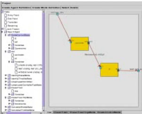
The Charon toolkit also includes a visual input language capability. It al- lows the user to draw agent and mode denitions in a hierarchical way, as shown in Figures 1 { 5. The interpreter of the visual input translates the specication into text-based Charon source code using an intermediate XML-based repre- sentation. The visual input tool is depicted in Figure 8.
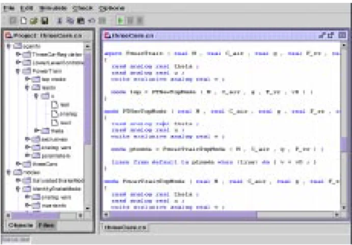
Once an edited and saved Charon language le exists, the user can simulate the hybrid system. In this case the Charon toolkit calls the parser and the type checker. If there are no syntactic errors, it generates a project context that is displayed in a separate project window that appears on the left hand side of the desktop, as shown in Figure 9.
The project window displays the internal representation of Charon in a convenient tree format. Each node in the tree may be expanded or collapsed by clicking it. The internal representation tree consists of two nodes: agents and
modes . They are initially collected from the associated Charon le.
A Charon specication describes how a hybrid system behaves over the course of time. Charon 's simulator provides a means to visualize a possible behavior of the system. This information can be used for debugging or simply for understanding in detail the behavior of the given hybrid system description.
The simulation methodology used in the Charon toolkit, which is depicted
in Figure 10, resembles concepts in code generation from a specication. As
Charon allows to write external Java source code the simulator needs to be an
executable Java program. Charon has a set of Java les that represent a core
Fig.8.
The visual input tool of
Charon: The agent car is dened as the composition of two other agents. The arrows depict variable renamings.
simulator. Given a Charon le, Java les are automatically generated which represent a Java interpretation of the Charon specication of a hybrid system.
They are used in conjunction with the predened simulator core les and the external Java source code to produce a simulation trace.
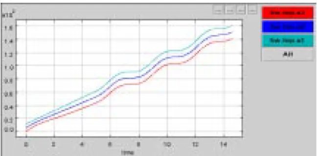
The Charon plotter allows the visualization of a simulation trace generated by the simulator. It draws the value of all selected variables using various colors with respect to time. It also highlights the time that selected transitions have been taken. A screen-shot of the plotter is given in Figure 11.
More information on the Charon toolkit, along with a preliminary release, is available at www.cis.upenn.edu/mobies/charon/ .
5 Research in Formal Analysis
Since Charon models have a precise semantics, they can be subjected to a vari- ety of analyses. In this nal section we will give a brief overview of our ongoing research eorts in formal analysis methods for hybrid systems. These include new techniques for accurate and ecient simulation, reachability analysis to de- tect violations of safety requirements, and abstraction methods for enhancing the applicability of analysis techniques.
Accurate event detection. The problem of accurately detecting and local-
izing the occurrence of transitions when simulating hybrid systems has received
an increased amount of attention in recent years. This is partially motivated
by the observation that the commonly used technique of simply checking the
value of the guards at integration points can cause the simulator not to detect
enabling of transitions. It has been shown that such inaccuracies can lead to
grossly inaccurate simulations due to the discontinuous nature of hybrid sys-
Fig.9.
The editor frame on the right hand side of the
Charondesktop and the cor- responding project frame on the left
CHARON model
external Java classes
Java simulation core files
files simulation Java
generated Java
Virtual Machine
Fig.10.
The simulation methodology of
Charontems. We have developed a method [15] which is guaranteed to detect enabling of all transitions. Our method has the advantage of being the only method which can properly detect such events when they occur in the neighborhood of model singularities. We select our step size in such a way as to steer the system toward the event surface without overshooting it.
Multirate simulation. Many systems, especially hierarchical ones, nat-
urally evolve on dierent time scales. For example the center of mass of an
automobile may be accelerating relatively slow compared to the rate at which
the crank shaft angle changes; yet, the evolution of the two are intimately cou-
pled. Despite this disparity, traditional numerical integration methods force all
coupled dierential equations to be integrated using the same step size. The
idea behind multi-rate integration method is to use larger step sizes for the slow
changing sets of dierential equations and smaller step sizes for the dierential
Fig.11.