Test and Calibration of Large Drift Tube Chambers With Cosmic Rays
Otmar Biebel, Tim Christiansen, Jörg Dubbert, Johannes Elmsheuser, Frank Fiedler, Ralf Hertenberger, Oliver Kortner, Thomas Nunnemann, Felix Rauscher, Dorothee Schaile, Arnold Staude, Raimund Ströhmer,
Balázs Újvári, and Cornelius F. Vollmer
Abstract—A cosmic ray measurement facility has been set up at Ludwig-Maximilians-University Munich (LMU) and is used at present to commission and calibrate Monitored Drift Tube (MDT) chambers for the muon spectrometer of the ATLAS experiment.
Each of these chambers—produced in collaboration with the Max-Planck-Institut für Physik and the Joint Institute for Nuclear Research in Dubna—consists of 432 drift tubes with a diam- eter of 3 cm, which are arranged in 2 3 layers, and measures 3.8 m 2.2 m 0.5 m. At the LMU site, the MDT chambers are completed, equipped with their final front-end electronics and taken into operation for the first time. The gas leak rate of the chamber is determined and its high voltage stability is tested. The response of all drift tubes and its homogeneity across the chamber is measured in the Cosmic Ray Facility. Two MDT chambers which were precisely mapped with an X-Ray tomograph provide reference tracking for the enclosed third chamber which is to be calibrated. The sense wire positions are determined from a com- parison of the drift time measurements with the reference tracks.
The geometry of the tested chamber—the grid constants of the drift tubes in a layer, the distances and tilt angles of the layers—can then be derived from these positions. Alignment systems are used to monitor chamber movements at the micrometer level. In the ongoing series commissioning, a rate of one chamber per week has been achieved. The parameters describing the geometry of the MDT chambers are determined with a precision in the 10 m range. The measurements with cosmic muons complement the chamber surveys performed during construction and will provide an important input for the calibration of the entire ATLAS muon spectrometer.
Index Terms—ATLAS, calibration, commissioning, cosmic ray, drift tube, Large Hadron Collider (LHC), Monitored Drift Tube (MDT) chamber, Muon spectrometer.
Manuscript received November 15, 2004. This work was supported in part by the Maier-Leibnitz-Laboratorium of the LMU and TU Munich, and the Bun- desministerium für Bildung und Forschung, Germany.
O. Biebel, J. Elmsheuser, F. Fiedler, R. Hertenberger, T. Nunnemann, F.
Rauscher, D. Schaile, A. Staude, R. Ströhmer, and C. F. Vollmer are with the Department für Physik, Ludwig-Maximilians-Universität, 80799 Munich, Germany.
T. Christiansen was with the Department für Physik, Ludwig-Maximil- ians-Universität, Munich, Germany. He is now with CERN, 1211 Genève 23, Switzerland.
J. Dubbert and O. Kortner were with the Department für Physik, Ludwig- Maximilians-Universität, Munich, Germany. They are now with Max-Planck- Institut für Physik (Werner-Heisenberg-Institut), 80805 Munich, Germany.
B. Újvári was with the Department für Physik, Ludwig-Maximilians-Univer- sität, Munich, Germany, on leave the from Department of Experimental Physics, Kossuth Lajos University, 4010 Debrecen, Hungary.
Digital Object Identifier 10.1109/TNS.2005.862907
I. INTRODUCTION
AT Hadron colliders, muons provide a very clean signature of particle’s decays in the background of the large number of high-multiplicity jets and interaction debris. Searches for new physics like Supersymmetry make extensive use of event topologies with muons and the golden channel for the discovery of a Standard Model Higgs boson in the mass range of 150–800 GeV is the decay . The discovery potential of hadron collider experiments, therefore, crucially depends on the identification of muons and the precise measurement of their momenta. As the scale of the detectors increases with rising center-of-mass energy of the collider, the muon systems, located at the outermost layers, have to cover larger and larger areas; the increasing transverse muon momentum demands either a larger field integral or detectors with improved spatial resolution to provide the precision of the momentum measurement required in physics analysis. In addition, the de- tectors have to cope with increasing background rates either of punch-through from the calorimeters or due to radioactivation of the inner detector parts. The activation and the complexity of the detectors also severely limit the possibilities of exchanging or repairing components during operation or even shutdown periods. Therefore, highly precise solutions have to be found which, at the same time, are cost-effective and reliable.
The muon spectrometer [1] of the ATLAS experiment at the Large Hadron Collider (LHC) at CERN is based on a toroidal air core magnet system consisting of a barrel and two endcap magnets with an average magnetic field strength of 0.4 T and a path length of about 5 m. Its instrumentation consists of 788 trigger chambers and a total of 1226 precision drift chambers covering an area of more than 5500 m . With 1194 units, Mon- itored Drift Tube (MDT) chambers constitute the vast majority of the precision detectors; only in the very forward, high rate regions Cathode Strip Chambers (CSCs) are employed.
The ATLAS muon spectrometer has been designed to be ca- pable of stand-alone operation (i.e., it does not require informa- tion from the inner detector parts to reconstruct muon tracks) with a resolution of better than 10% for muon momenta up to 1 TeV. To achieve this ambitious goal with a three point sagitta measurement (two stations are located at the inner and outer edge of the toroidal magnet, one station inside the magnetic field), the precision chambers must reach a point resolution of better than 50 m. This resolution then leads to the requirement that wire positions and the chamber geometry must be known with an RMS of 20–30 m.
0018-9499/$20.00 © 2005 IEEE
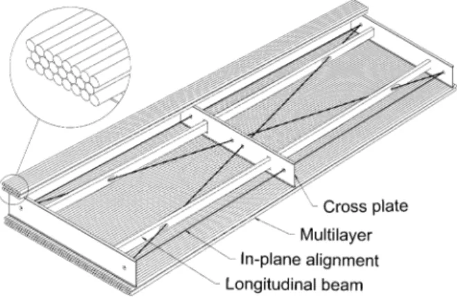
Fig. 1. Schematic view of an ATLAS barrel MDT chamber.
Measurements with cosmic ray muons offer the pos- sibility to test MDT chambers before installation in the experiment. The Cosmic Ray Measurement Facility at Ludwig-Maximilians-University (LMU), Munich, also al- lows the determination of the individual anode wire positions and the chamber geometry, in addition to a complete chamber and front-end electronic test and commissioning. The measured chambers provide valuable anchor points for the calibration of the ATLAS muon spectrometer at LHC.
II. MONITOREDDRIFTTUBECHAMBERS
Drift tubes are long, cylindrical, gas-filled ionization detec- tors with a single centered sense wire. The determination of the impact radius of a charged particle within a tube is based on the measurement of the drift time of the electrons from the primary ionization to the anode wire with respect to an external trigger signal; a so-called rt-relation is then used to convert drift time information to a radius prediction. The rt-relation can either be measured with the help of an external reference system, or in the case of MDT chambers by an iterative self-calibrating algo- rithm, the auto-calibration [2], [3].
ATLAS MDT chambers [1] consist of two multilayers, each built of 3 or 4 layers of densely packed drift tubes, mounted on an aluminum support frame (compare Fig. 1); the chamber sizes vary from about 1 m to 11 m while tube lengths range from 1 m to 6 m. The individual drift tubes are also made of alu- minum, have an outer diameter of 30 mm and a wall thickness of 400 m. A goldplated W-Re anode wire with a diameter of 50 m is stretched with a wire tension equivalent to 350 g in the center of the tube. The anode wire is fixed only at the tube ends using precision endplugs for centering; the sag of the wires in the tubes can be compensated by bending the chamber with respect to the support frame. The tubes are operated with an gas mixture at 3 bar absolute pressure at a gas gain of (corresponding to a high voltage of 3080 V). An average single tube resolution of 100 m can be achieved. The maximum drift time for electrons from hits near the tube wall to the anode wire is about 700 ns.
The geometry of the drift tube chamber is constantly mon- itored by optical alignment systems mounted in the support structure. These so-called RasNiK [4] sensors consist of a backlit mask which is projected by a lens onto a CCD camera.
Analysis of the chessboard-like pattern of the mask image
allows the determination of shifts of the sensor components perpendicular to the optical axis with a precision of 1 m.
III. THELMU COSMICRAYMEASUREMENTFACILITY
The Cosmic Ray Measurement Facility at LMU is cur- rently used to commission and calibrate 88 BOS/BOF MDT chambers built at the Max-Planck-Institut für Physik, Mu- nich, [5]–[7]. These chambers—the second largest type in the ATLAS barrel region, which will be mounted on the outside of the toroid magnet coils (BarrelOuterSmall) and be- tween the detector support feet (BarrelOuterFoot)—measure 3.8 m 2.2 m 0.5 m and consist of 2 3 layers with 72 tubes per layer. At present, one chamber is tested per week.
Fig. 2 shows a schematic view of the setup of the Cosmic Ray Measurement Facility at LMU [8]. The setup is located in an air-conditioned hall to ensure stable environmental conditions during data taking.
Three MDT chambers are operated simultaneously in the test stand; the upper and lower chamber (the so-called reference chambers) provide tracking of the cosmic muons for the en- closed middle chamber, which is to be tested and calibrated. The anode wire positions of the two reference chambers have been measured with an X-ray tomograph [9] at CERN and are known with a precision of a few micrometers.
The cosmic ray trigger is provided by a coincidence of two scintillator hodoscopes located above and below the drift cham- bers. An iron absorber above the lower hodoscope plane is used to suppress cosmic muons with an energy of less than 600 MeV.
The trigger logic is divided into five segments along the tubes ( -axis) to limit the inclination angle of the muons in the - plane, thus avoiding correlations between the two ends of the chambers in the track reconstruction. The trigger covers the complete chamber area of approx. 8.5 m and has a time res- olution of better than 800 ps. Both hodoscopes consist of indi- vidual scintillator panels of about 10 cm width which allow the measurement of the track coordinate along the -axis with a res- olution of 7.5 cm.
An estimate of the muon momentum is obtained by mea- suring the multiple scattering angle in the iron absorber with the lower reference chamber and two layers of streamer tubes at the bottom of the setup.
Two alignment systems are used to continuously monitor the position of all three MDT chambers. The relative positions of the two reference MDT chambers are measured with an optical system consisting of 8 RasNiK sensors in all three spatial direc- tions, the position of the test chamber with respect to the upper reference chamber is measured by a system of eight capacitive sensors which is sensitive in the - plane. Both alignment sys- tems reach an accuracy of better than 5 m.
The setup allows the test chamber to be moved in either -di- rection by about one third of its width to increase the trigger acceptance for hits at its edges, which is low for geometrical reasons in the center position.
IV. CHAMBERCOMMISSIONING
MDT chambers have to pass several stringent tests to be cer- tified for installation in the ATLAS detector. This section will
Fig. 2. Setup of the LMU Cosmic Ray Measurement Facility. All dimensions in mm.
focus on the leak rate measurement, the tube response and the chamber homogeneity.
A. Chamber Leak Rate
The maximum allowed leak rate of a MDT chamber is lim-
ited to (bar L)/s, where denotes
the number of tubes of a chamber. This limit was introduced to keep the backdiffusion of air into the recirculating gas system minimal, in order to avoid changes of the drift properties and efficiency losses due to the attachment of primary ionization electrons to the electronegative oxygen. For a BOS/BOF MDT chamber with 432 tubes, the maximum allowed leak rate is therefore (bar L)/s.
The gas distribution system mounted on each BOS/BOF MDT chambers contains 3460 O-ring seals. The leak detection is performed with a He detector in sniffer mode using an Ar/He mixture at 3 bar (2.6 bar Ar, 0.4 bar He).
The leak rate is determined by measuring the pressure drop of a chamber over time. For BOS/BOF chambers the ATLAS leak rate limit translates to a pressure drop of only 0.68 mbar/day.
The measurement is performed with an absolute pressure gauge with 0.1 mbar resolution and corrected for temperature effects (a change of K corresponds to a pressure change of mbar). To reach a precision of better than the allowed leak rate, 3–5 d of measurement time are needed.
As can be seen in Fig. 3, the 31 MDT chambers measured so far fulfill the leak rate requirement within the measurement
Fig. 3. Leak rates of 31 BOS/BOF MDT chambers. The shaded region is the allowed range of leakage.
errors. A total of 0.03% of tubes had to be disconnected from the gas system due to nonrepairable gas leaks.
B. Tube Response and Homogeneity
The tube response is determined by measuring the drift time spectrum of the tube. The drift time spectrum is the time distri- bution of all hits (more precisely: of all first hits, as the MDT front-end electronics are capable of recording more than one hit per event), corrected for their signal propagation time in the tube; small drift times correspond to hits near the anode wire, large drift times to hits near the tube wall. If a drift tube is ho- mogeneously illuminated with muons, its spectrum is a charac- teristic of the gas mixture and the operating conditions, as the
Fig. 4. Example of an drift time spectrum. The circles mark the spectrum of one individual tube in the MDT chamber, the shaded histogram represents the average drift time spectrum of the whole chamber (432 tubes). The lines show the analytic functions,F (t)andG(t), fitted to the beginning and the end of the spectrum to derive the parameter set of the tube.
number of entries at a given time is then proportional to the elec- tron drift velocity at the corresponding position of the muon’s transit.
To compare the drift time spectra of all tubes in a MDT chamber, the shape of each spectrum is parameterized with analytic functions at the leading and at the trailing edge [10]
(1)
(2) The parameters and correspond to the rates of accidental hits and are related to the noise rate of the tube. denotes the height of the spectrum. (mid-time) is a time offset de- pending on the read-out electronics and cabling, and is the steepness of the leading edge, and is correlated to the resolution of the tube near the anode wire which is influenced by signal amplification and the discriminator threshold of its front-end electronics channel. Correspondingly, is the mid-time of the trailing edge and is related to its steepness, which is de- termined by the decreasing detection efficiency caused by the decreasing pulse height due to the reduced path length and pri- mary ionization of tracks passing near the tube wall. The term approximates the slope of the drift time spectrum before the trailing edge due to the decreasing drift velocity near the tube wall.
Fig. 4 shows an example of a drift time spectrum and the fitted
functions and .
From the fit parameters the maximum drift time, defined as can be derived. Fig. 5 shows, for 31 BOS/BOF MDT chambers, the average maximum drift time for the two multilayers. A very good agreement between the drift prop- erties of the multilayers can be observed, the mean deviation is ns, far less than the RMS spread of the individual drift tubes in one multilayer of about ns. Therefore, no systematic deviation on the position measurement between the multilayers of a MDT chamber has been observed.
Fig. 5. Average maximum drift time for the lower (ML 1) and upper (ML 2) multilayers of 31 BOS/BOF MDT chambers. The error bars are the RMS spread of the maximum drift time of the drift tubes.
V. MEASUREMENT OF THEANODEWIREPOSITIONS AND
CHAMBERGEOMETRY
The precise tracking of incident muons at the Cosmic Ray Measurement Facility allows the measurement of individual anode wire position within the tested chamber. Before de- scribing the method of the measurement, the determination of the rt-relation, tracking, chamber alignment, muon energy estimation, and event selection are explained briefly; a detailed description of these topics can be found in [8].
A. rt-Relation
To convert the measured drift times to a drift radius within a tube, a so-called rt-relation is necessary. At the Cosmic Ray Measurement Facility, the rt-relation is determined without any external reference, using only the information from the installed MDT chambers.
After the check of the chamber homogeneity (compare Sec- tion IV-B), it is assumed that the space-drift time relation is the same for all tubes in one multilayer of a MDT chamber. The rt-relation is then determined with an iterative auto-calibration algorithm [2], [3], where the deviations of the individual tube
measurements from a track fit in the chamber are used to de- rive corrections to improve the space-drift time relation. The ini- tial estimate is based on the rt-relation of the last measurement, scaled to the current maximum drift time to allow for changes in the chamber gas composition between different data taking periods. The algorithm then usually converges with less than 5 iterations with a precision of about 20 m on the space-drift time relation, which leads to a negligible systematic error in the anode wire position measurement.
B. Tracking
The muon track segments reconstructed in each MDT chamber are assumed to be straight lines in the - plane (the third coordinate is only used to correct for signal propagation times in the tubes and for the wire sag; it is taken from the hodoscope information)
(3) The parameters and are determined for each chamber by minimizing the -function
(4)
where the index runs over all contributing tubes, is the distance of the track segment to the anode wire, the measured drift radius, and the resolution of the tube for the given radius. The intrinsic single tube resolution was obtained in a test beam measurement [11] with an external reference system of silicon microstrip detectors and is around 100 m.
C. Chamber Alignment
The MDT chambers in the Cosmic Ray Measurement Facility are aligned mechanically with a precision of about 100 m. A much more precise estimate of their relative positions can be de- rived from the comparison of the reconstructed track segments in each of the reference chambers with the test chamber (which is assumed to be in its nominal position). Relative translations in the - and -direction between the chambers lead to system- atic deviations of the track intercept parameters (compare (3)) and can be determined with 1 m and 10 m precision, re- spectively. A translation in the -direction can be ignored, as the mounting precision and stability is several orders of magnitude better than the track resolution of the hodoscope; furthermore, the chambers are insensitive to small shifts along the direction of the anode wires. A tilt angle around the -axis leads to a sys- tematic deviation of the measured track slopes . A precision of 1 rad is reached. The angles of rotation around the - and -axis are determined indirectly with a precision of 10 rad and 1 rad from the chamber translations measured at the two ends of the MDT chamber.
The information from the optical and capacitive alignment systems can be used to further correct for time dependent move- ments of the chambers.
TABLE I
CUMULATIVEEFFICIENCY OF THEEVENTSELECTIONCUTS(SEETEXT FOR FURTHEREXPLANATIONS). THENUMBER OFEVENTSPERMETER OFTUBE
LENGTH FOR ADATATAKINGPERIOD OF24 h AREALSOGIVEN
D. Muon Energy Estimation
The energy of cosmic muons traversing the Cosmic Ray Mea- surement Facility is estimated from their multiple scattering in the middle MDT chambers and the iron absorber.
The probability density for measuring a difference in the track slopes between the upper and lower reference cham- bers and a deviation between the hit position in the streamer tubes and the one predicted from the track in the lower reference chamber is given by
(5)
where and are the energy dependent stan- dard deviations of and , determined from Monte-Carlo simulations [12].
For a given track, the value of that maximizes the den- sity-function is an estimate of the muon energy. This es- timator is biased and of limited resolution but is still useful for a selection of high energetic muons.
E. Event Selection
Events used in the analysis of the anode wire positions have to pass four selection cuts to ensure their quality.
Only events with one hit in each, the upper and the lower, hodoscope are accepted in order to guarantee an unambiguous trigger time and a unique -coordinate for the tube hits. The second cut demands the existence of a track segment with at least 5 hits in each of the three MDT chambers, and a rough matching of all intercept and slope parameters. The remaining tracks are calledgood tracks. To limit the effects from multiple scattering on the analysis an estimated muon energy E larger than 2.5 GeV is required. In a final step, hits caused by -rays are suppressed by demanding that the tube’s hit has contributed to the track fit and by a very loose matching of the measured drift radius with the track prediction.
The cumulative efficiency of the event selection and the number of events collected per unit tube length within 24 hours of data taking are summarized in Table I.
Fig. 6. Deviations between the predicted and the measured impact radius caused by displacements and of the anode wire.
F. Measurement Method
The measurement of the wire positions is based on the com- parison of predicted impact radii extrapolated from the track segments measured in the two reference chambers with the ac- tual measurement , derived from the measured drift time, in a given tube of the test chamber. The impact radius prediction is a weighted average of the upper (u) and lower (l) refer- ence chamber’s track segments
(6) taking into account the geometrical position of the tested tube relative to the reference chambers, and the energy estimate of the muon, as calculated from its multiple scattering in the MDT chambers and the iron absorber, and of the track resolutions . The value of is about 200 m for the reference chamber closer to the tube hit and ranges from 300–800 m for the far- ther chamber.
Displacements of the anode wire from its nominal position in the chamber lead to systematic deviations in the distribution of its residuals (compare Fig. 6)
(7) Here, denotes the wire displacement in the chamber plane, the displacement perpendicular to it, and the track slope as defined in (3).
The wire displacement in the -direction can be calculated from a linear fit of as a function of the track slope . The displacement in the -direction is obtained from the mean value
of the residuals , where the residuals
are calculated with corrected positions.
G. Performance of the Cosmic Ray Measurement Facility The performance of the Cosmic Ray Measurement Facility was investigated using one of the few chambers which were sur- veyed in the X-Ray tomograph [9] at CERN as a test chamber.
The accuracy of the Cosmic Ray Measurement Facility is de- rived by comparing the results from an analysis of cosmic ray data taken during 48 hours with measurements at the X-Ray tomograph, which have a precision of 2 m. Fig. 7 shows an
Fig. 7. Comparison between the measurements of the wire displacements with the Cosmic Ray Measurement Facility and the results from the X-Ray tomograph. Shown are the wire displacements in the chamber plane for one side of a BOS chamber. The apparent shift of the wire positions between the lower (ML 1) and upper (ML 2) multilayer is due to a slight relative rotation of these multilayers, a known production error of this particular chamber.
example of the correlation between the two measurements. Per- pendicular to the chamber plane, we obtain an accuracy of
m for individual wire displacements and m for layer shifts. The tilt angle around the wire axis, , can be measured with a precision of 17 rad. In the chamber plane, an
accuracy of m and m is achieved. The
grid constant (i.e., the mean wire spacing in a layer) can be de- termined with 0.15 m precision. The results are in agreement with previous Monte-Carlo studies [12].
H. Results
For each MDT chamber measured in the LMU Cosmic Ray Measurement Facility the individual anode wire positions are determined at both ends of the chamber (i.e., the read-out side and the high voltage side of the tubes near the endplugs). From these wire positions the layer and multilayer distances, displace- ments, rotations, and grid constants are obtained. In combina- tion with slow control data from temperature sensors and the chamber alignment monitors a complete geometrical descrip- tion of the chamber is derived. As an example, Fig. 8(a) shows the deviation of the vertical distance of the multilayers from their nominal value for the first 31 measured MDT chambers at the high voltage side, Fig. 8(b) the relative horizontal dis- placement of the multilayers at the read-out side. The square points mark repaired chambers with re-glued multilayers which are known to deviate from their nominal positions.
VI. CONCLUSION
At the Cosmic Ray Measurement Facility at Ludwig-Maxi- milians-University (LMU) large MDT chambers for the ATLAS muon spectrometer are commissioned and calibrated at a rate of one chamber per week. The chambers—built at the Max- Planck-Institut für Physik—are leak tested at the LMU, put into
Fig. 8. Results for the first 31 ATLAS BOS/BOF MDT chambers. Chambers are ordered by their date of production. The square points mark repaired chambers. The error bars are the RMS spread of the deviations of the single tubes from the multilayer fit. (a) Measurement of the displacement of the two multilayers from their nominal vertical separation at the high voltage chamber side. (b) Measurement of the displacement of the two multilayers in the chamber plane at the read-out chamber side.
operation for the first time and are completely tested, including their front-end and chamber service electronics. The individual anode wire positions of each chamber are determined with a precision of (10 m), the chamber geometry with a precision of a few micrometers.
The first 31 of 88 BOS/BOF MDT chambers have been commissioned. The chambers fulfill the ATLAS leak rate limit and show a homogeneous response of their drift tubes. The chamber geometry is consistent throughout the production time and fulfills the ATLAS specifications. These MDT chambers will provide valuable anchor points for the calibration of the entire ATLAS muon spectrometer with LHC data.
ACKNOWLEDGMENT
We would like to thank our engineer Mr. H. Steffens, our technician Mr. A. Varga and the staff of the mechanical and electrical workshops at the LMU Physics Department for their ongoing help.
REFERENCES
[1] “ATLAS Muon Spectrometer Technical Design Report,” CERN, Geneva, Switzerland, May 1997. ATLAS Muon Collaboration, CERN/LHCC/97-22.
[2] G. Viehhauser, “Detector Physics of the ATLAS Precision Chambers,”
Ph.D. dissertation, Vienna University of Technology, 1996.
[3] M. Deile, “Optimization and Calibration of the Drift-Tube Chambers for the ATLAS Muon Spectrometer,” Ph.D. dissertation, Ludwig-Maximil- ians-University Munich, May 2000.
[4] H. van der Graafet al., “RasNiK, an Alignment System for the ATLAS MDT Barrel Muon Chambers—Technical System Description”, Apr.
2000. NIKHEF/ET38110.
[5] F. Bauer et al., “Large-Scale Production of the Precision Drift Tube Chambers for the ATLAS Muon Spectrometer,” MPI Report, Apr. 2002.
MPP-2002-160.
[6] F. Baueret al., “Construction and test of MDT chambers for the ATLAS muon spectrometer,”Nucl. Instrum. Methods Phys. Res. A., vol. A461, pp. 17–20, Apr. 2001.
[7] F. Baueret al., “Construction and test of the precision drift chambers for the ATLAS muon spectrometer,”IEEE Trans. Nucl. Sci., vol. 48, no. 3, pp. 302–307, Jun. 2001.
[8] O. Biebelet al., “A Cosmic Ray Measurement Facility for ATLAS Muon Chambers”, Jul. 2003. e-Print physics/0 307 147.
[9] J. Berbierset al., “High-precision X-ray tomograph for quality control of the ATLAS muon monitored drift chambers,”Nucl. Instrum. Methods Phys. Res. A, vol. A419, pp. 342–350, 1998.
[10] O. Kortner and F. Rauscher, “Automatic Synchronization of Drift-Time Spectra and Maximum Drift-Time Measurement of an MDT”, 2002.
ATL-MUON-2005-012, CERN.
[11] J. Dubbertet al., “Resolution and Efficiency of Monitored Drift-Tube Chambers with Final Read-out Electronics at High Background Rates”, Dec. 2003. ATL-MUON-2004-002, CERN.
[12] O. Kortner, “Schauerproduktion durch hochenergetische Myonen und Aufbau eines Höhenstrahlungsprüfstands für hochauflösende ATLAS-Myonkammern,” Ph.D. dissertation, Ludwig-Maximil- ians-University Munich, Mar. 2002.