PROTOCOLL ARCHITECTURE
This architecture was developed by the IEEE 802 committee and has been adopted by all organizations working on the specification of LAN standards.
It is generally referred to as the IEEE 802 reference model. Working from the bottom up, the lowest layer of the IEEE 802 reference model corresponds to the physical layer of the OSI model and includes such function as
• Encoding/decoding of signals
• Preamble generation/removal
• Bit transmission/reception
In addition, the physical layer of the 802 model includes a specification of the transmission medium and topology. Generally, this is considered ”below” the lowest layer of the OSI model. However, the choice of transmission medium and topology is critical in LAN design and so a specification of the medium is included. Above the physical layer there are the functions associated with providing service to LAN users. These includes the following:
• On transmission, assemble data into a frame with address and error detection fields.
• On reception, disassemble frame, and perform address recognition and error detection.
• Govern access to the LAN transmission medium.
• Provide an interface to higher layers and perform flow and error control.
These are functions typically associated with OSI layer 2. The set of functions are grouped into a logical link control (LLC) and in a separate layer called medium access control (MAC). The separation is done because the logic required to manage access to a shared-access medium is not found in traditional layer 2 data link control and also because for the same LLC, several MAC options may be provided.
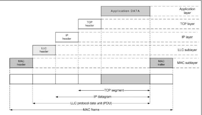
Figure 1:
Service Access Points (SAPs)
Multiple link service access points (LSAPs) provide interface ports to support multiple higher layer users. The MAC sublayer provides a single interface port to the LLC sublayer. The Physical layer provides an interface port to a single MAC station. A user of LLC is identified by, at a minimum, the logical concatenation of the MAC address fields and the LLC address fields (LSAPs) in a frame. Figure 1 illustrates the relationship between the levels of the two architecture.
Higher level data are passed down to LLC, which appends control information as a header, creating an LLC protocol data unit (PDU). This control information is used in the operation of the LLC protocol.
The entire LLC PDU is then passed down to the MAC layer, which appends control information at the front and back of the packet, forming a MAC frame as shown in Figure 2. Again, the control
information in the frame is needed for the operation of the MAC protocol.
Figure 2: IEEE 802 Protocols in context
LLC SUBLAYER
The LLC sublayer standard describes three types of operations for data communication between service access points:
• unacknowledged connectionless service - type 1 operation.
With type 1 operation, information frames are exchanged between LLC entities without the need for the prior establishment of a logical link between peers. These LLC frames are not
acknowledged, nor are there any flow control or error recovery procedures.
• connection-oriented service - type 2 operation.
With type 2 operation, a logical link is established between pairs of LLC entities prior to any exchange of information frames. In the data transfer phase of operation, information frames are transmitted and delivered in sequence. Error recovery and flow control are provided.
• acknowledged connectionless service - type 3 operation.
With type 3 operation, information frames are exchanged between LLC entities without the need for the prior establishment of a logical link between peers. However, the frames are
acknowledged to allow error recovery and proper ordering. Further, type 3 operation allows one station to poll another for data.
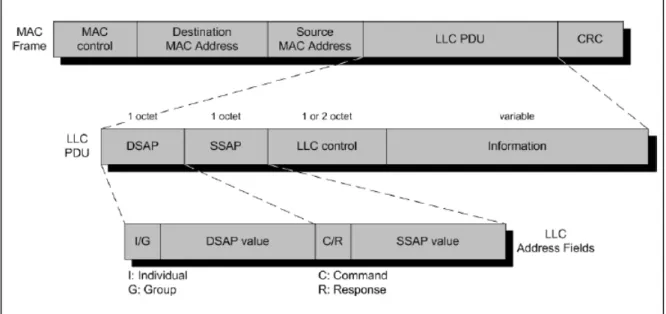
As shown in Figure 3, all three LLC operations employ the same PDU format, which consists of four fields:
• Destination SAP (DSAP): contains a 7-bit address and specify the destination user of LLC.
• Source SAP (SSAP): contains a 7-bit address and specify the source user of LLC.
• LLC control: contains LLC control data (data flow control etc.); it’s 1 byte in length when used
connectionless services and 2 bytes in length when used connection-oriented services.
• Information: this field indicates which type of operation may be provided for that particular
SSAP. For a SAP that supports type 2 operation, and for a particular connection, the information field also includes the receive window size used in the sliding-window mechanism. The field’s size is variable, but it must be an integer multiple of 1 byte.
Figure 3: LLC PDU in a generic frame format
MAC SUBLAYER
The MAC sublayer performs access control functions for the shared medium in support of the LLC sublayer. For different applications, different MAC options may be required. The MAC sublayer performs the addressing and recognition of frames in support of LLC. MAC also performs other functions, such as frame check sequence generation and checking, and LLC protocol data unit (PDU) delimiting.
The exact format of the MAC frame differs for the various MAC protocols in use. In general all the MAC frames have a format similar to the one of the Figure 3. The fields of this frame are as follows:
• MAC control: this field contains any protocol control information needed for the functioning of
the MAC protocol (e.g. priority level).
• Destination MAC address: the destination physical attachment point on the LAN for this frame.
• Source MAC address: the source physical attachment point on the LAN for this frame.
• Data: the body of the MAC frame. This may be LLC data from the next higher layer or control
information for the MAC protocol.
• CRC: the cyclic redundancy check field is an error-detecting code.
The MAC sublayer is also responsible for detecting errors and discarding any frames that are in error.
PROTOCOL ARCHITECTURE
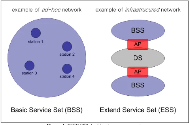
802.11 was the first IEEE standard adopted (first release in 1997, current version in 1999) for wireless LANs (WLAN). Figure 4 illustrates the model developed by the 802.11 working group.
The smallest building block of a wireless LAN is a basic service set (BSS), which consists of some number of stations executing the same MAC protocol and competing for access to the same shared wireless medium. A BSS may be isolated or it may connect to a backbone distribution system (DS) through an access point (AP). The access point functions as a bridge. The MAC protocol may be fully distributed or controlled by a central coordinator function housed in the access point. The DS can be a switch, a wired network or a wireless network.
The simplest configuration is the one in which each station belongs to a single BSS; in this case, each station is within wireless range only of other stations within the same BSS. There is the opportunity to overlap geographically two BSS, so that a single station could participate in more than one BSS. The association between a station and a BSS is dynamic, so the station is allowed to turn off, come with range and go out of range.
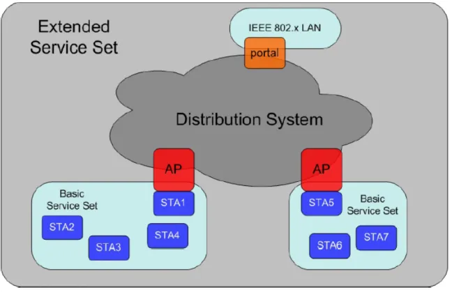
An extended service set (ESS) consists of two or more BSS interconnected by a distribution system (an example is shown in Figure 5). Consequently the extended service set appears as a single logical LAN to the logical link control (LLC) level. A portal is used when it’s needed to integrate the IEEE 802.11 architecture with a traditional wired LAN. This portal is usually implemented in a device such a bridge or a router belonging to the wired LAN and attached to the DS.
Figure 4: IEEE 802 Architecture components
SERVICES
IEEE 802.11 defines nine services that need to be provided by the wireless LAN to provide
functionality equivalent to that which is inherent to wired LANs. The services provider can be either the station or the distribution system.
Figure 5: ESS structure example
STATION SERVICES
The 802.11 standard defines services for providing functions among stations.
Station services are implemented within all stations on an 802.11 WLAN (including
access points). The main thrust behind station services is to provide security and data delivery services for the WLAN. The four station services and functions detailed below include: authentication, de- authentication, privacy and data delivery.
1) Authentication
Because wireless LANs have limited physical security to prevent unauthorized access, 802.11 defines authentication services to control access to the WLAN. The goal of authentication service is to provide access control equal to a wired LAN. The authentication service provides a mechanism for one station to identify another station. Without this proof of identity, the station is not allowed to use the WLAN for data delivery. All 802.11 stations, whether they are part of an independent BSS or ESS network, must use the authentication service prior to communicating with another station. IEEE 802.11 defines two types of authentication services: Open System Authentication and Shared Key Authentication.
Open System Authentication is the default authentication method, which is a very simple, two-step process. First the station wanting to authenticate with another station sends an authentication
management frame containing the sending station’s identity. The receiving station then sends back a frame alerting whether it recognizes the identity of the authenticating station.
Shared Key Authentication assumes that each station has received a secret shared key through a secure channel independent of the 802.11 network. Stations authenticate through shared knowledge of the secret key. Use of shared key authentication requires implementation of encryption via the Wired Equivalent Privacy (WEP) algorithm.
2) De-Authentication
The de-authentication service is used to eliminate a previously authorized user from any further use of the network. Once a station is de-authenticated, that station is no longer able to access the WLAN
without performing the authentication function again. De-authentication is a notification and cannot be refused. For example, when a station wishes to be removed from a BSS, it can send a de-authentication management frame to the associated access point to notify the access point of the removal from the network. An access point could also de-authenticate a station by sending a de-authentication frame to the station.
3) Privacy
The privacy service of IEEE 802.11 is designed to provide an equivalent level of protection for data on the WLAN as that provided by a wired network with restricted physical access. This service protects that data only as it traverses the wireless medium. It is not designed to provide complete protection of data between applications running over a mixed network. With a wireless network, all stations and other devices can ”hear” data traffic tacking place within range on the network, seriously impacting the security
level of a wireless link. IEEE 802.11 counters this problem by offering a privacy service option that raises the security of the 802.11 network to that of a wired network. The privacy service, applying to all data frames and some authentication management frames, is an encryption algorithm based on the 802.11 WEP algorithm.
4) Data Delivery
Data delivery service is similar to that provided by all other IEEE 802 LANs. The data delivery service provides reliable delivery of data frames from the MAC in one station to the MAC in one or more other stations, with minimal duplication and reordering of frames.
DISTRIBUTION SERVICES
Distribution services provide functionality across a distribution system. Typically, access points provide distribution services. The five distribution services and functions detailed below include: association, disassociation, reassociation, distribution, and integration.
1) Association
The association service is used to make a logical connection between a mobile station and an access point. Each station must become associated with an access point before it is allowed to send data through the access point onto the distribution system. The connection is necessary in order for the distribution system to know where and how to deliver data to the mobile station. The mobile station invokes the association service once and only once, typically when the station enters the BSS. Each station can associate with one access point though an access point can associate with multiple stations.
2) Disassociation
The disassociation service is used either to force a mobile station to eliminate an association with an access point or for a mobile station to inform an access point that it no longer requires the services of the distribution system. When a station becomes disassociated, it must begin a new association to communicate with an access point again.
An access point may force a station or stations to disassociate because of resource restraints, the access point is shutting down or being removed from the network for a variety of reasons. When a mobile station is aware that it will no longer require the services of an access point, it may invoke the
disassociation service to notify the access point that the logical connection to the services of the access point from this mobile station is no longer required. Stations should disassociate when they leave a network, though there is nothing in the architecture to assure this happens. Disassociation is a
notification and can be invoked by either associated party. Neither party can refuse termination of the association.
3) Re-Association
Re-association enables a station to change its current association with an access point. The re-
association service is similar to the association service, with the exception that it includes information about the access point with which a mobile station has been previously associated. A mobile station will use the re-association service repeatedly as it moves through out the ESS, loses contact with the access point with which it is associated, and needs to become associated with a new access point. By using the re-association service, a mobile station provides information to the access point to which it will be associated and information pertaining to the access point which it will be disassociated. This allows the newly associated access point to contact the previously associated access point to obtain frames that
may be waiting there for delivery to the mobile station as well as other information that may be relevant to the new association. The mobile station always initiates re-association.
4) Distribution
Distribution is the primary service used by an 802.11 station. A station uses the distribution service every time it sends MAC frames across the distribution system. The distribution service provides the distribution with only enough information to determine the proper destination BSS for the MAC frame.
The three association services (association, re-association, and disassociation) provide the necessary information for the distribution service to operate. Distribution within the distribution system does not necessarily involve any additional features outside of the association services, though a station must be associated with an access point for the distribution service to forward frames properly.
5) Integration
The integration service connects the 802.11 WLAN to other LANs, including one or more wired LANs or 802.11 WLANs. A portal performs the integration service as shown in Figure 5. The portal is an abstract architectural concept that typically resides in an access point though it could be part of a separate network component entirely. The integration service translates 802.11 frames to frames that may traverse another network, and vice versa as well as translates frames from other networks to frames that may be delivered by an 802.11 WLAN.
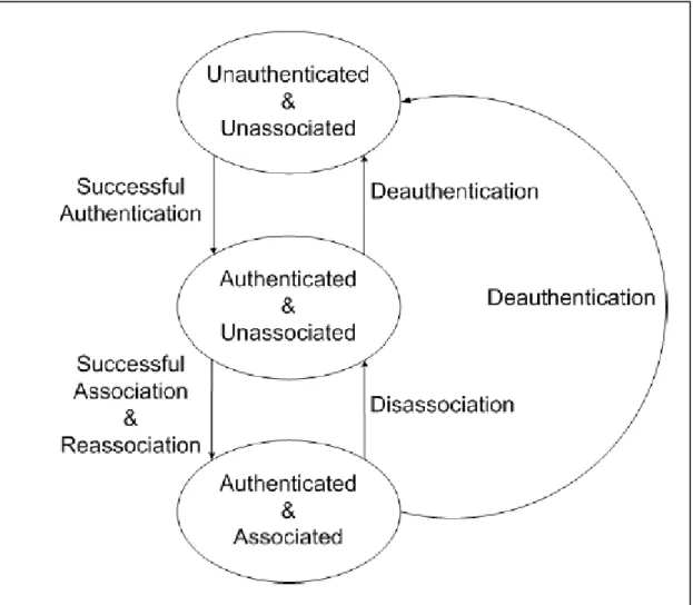
AUTHENTICATION & ASSOCIATION
As shown before, the need of a client to be mobile brought in the separation of authentication and association processes. Since a client frequently changes AP boundaries, it can be authenticated to various AP at a given point, yet remains associated to its chosen one. Before a client gets associated to other, it must be first authenticated. This procedure is shown in Figure 6.
Figure 6: Authentication & Association procedure
MEDIUM ACCESS CONTROL - MAC
RELIABLE DATA DELIVERY
The 802.11 MAC layer provides functionality to allow reliable data delivery for the upper layers over the wireless PHY media. The data delivery itself is based on an asynchronous, best-effort,
connectionless delivery of MAC layer data. There is no guarantee that the frames will be delivered successfully. For this reason, IEEE 802.11 includes a frame exchange protocol. When a station receives a data frame from another station it returns an acknowledgment frame (ACK) to the source station. This exchange can not to be interrupted by a transmission from any other station. If the source does not receive an ACK within a short period of time, it retransmits the frame.
To further enhance reliability, a four frame exchange may be used. A source first issues a Request To Send (RTS) frame to the destination; the destination then responds with a Clear To Send (CTS). After receiving the CTS, the source transmits the data frame and wait for the corresponding ACK from the destination. The RTS and CTS alert all stations that are within reception range of the source that an exchange is under way; these stations renounce to transmit in order to prevent collisions. The RTS/CTS portion of the exchange is a required function of the MAC, but may be disabled.
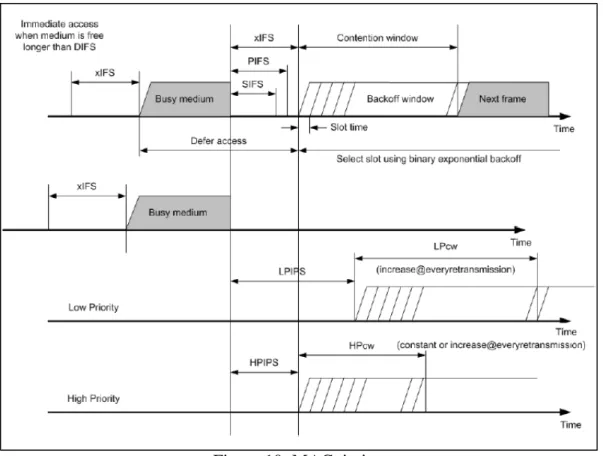
ACCESS CONTROL
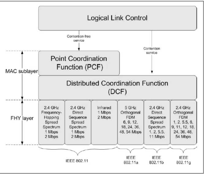
The 802.11 MAC algorithm is called Distributed Foundation Wireless MAC (DFWMAC) and provides a distributed access control mechanism with an optional centralized control built on top of that. Figure 7 illustrates this architecture.
Figure 7: IEEE 802.11 Protocol architecture
The lower sublayer of the MAC is the Distributed Coordinator Function (DCF). DCF uses a contention algorithm to provide access to all traffic.
Ordinary asynchronous traffic directly uses DCF. The Point Coordinator Function (PCF) is a
centralized MAC algorithm used to provide contention-free service. PCF is built on top of DCF and
exploits features of DCF to assure access for its users.
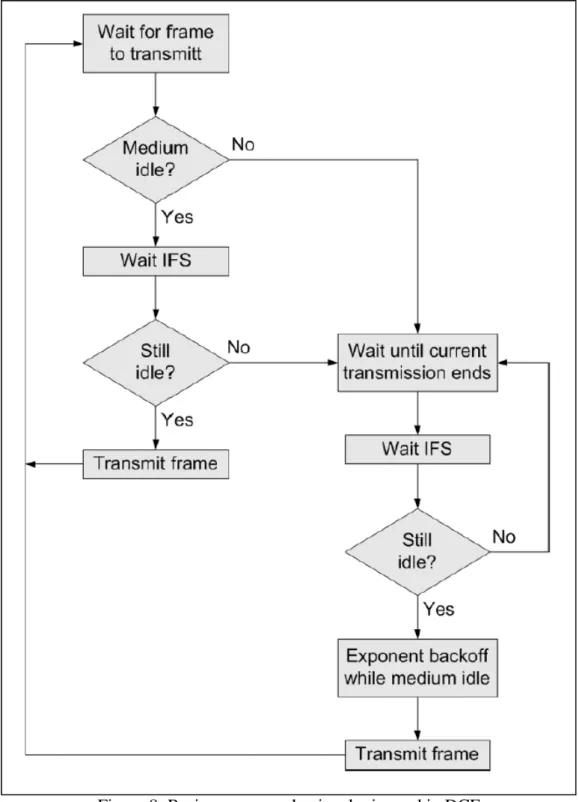
DISTRIBUTED COORDINATOR FUNCTION (DCF)
The DCF sublayer makes use of a simple CSMA algorithm. DCF defines a basic two-way handshaking access mechanism and an optional four-way handshaking mechanism.
Figure 8: Basic access mechanism logic used in DCF
A station with a new packet to transmit monitors the channel activity. If the channel is idle for a period of time equal to a Distributed Inter-Frame Space (DIFS), the station transmits. Otherwise, if the channel is sensed busy (either immediately or during the DIFS), the station persists to monitor the channel until it is measured idle for a DIFS. At this point, the station generates a random backoff interval before transmitting (this is the ”Collision Avoidance” feature of the protocol) to minimize the probability of collision with packets being transmitted by other stations. In addition, to avoid channel capture, a station must wait a random backoff time between two consecutive new packet
transmissions, even if the medium is sensed idle in the DIFS time. The logic flow chart of this mechanism is shown in Figure 8.
For efficiency reasons, DCF employs a discrete-time backoff scale. The time immediately following
an idle DIFS is slotted, and a station is allowed to transmit only at the beginning of each slot time.
The slot time size is set equal to the time needed at any station to detect the transmission of a packet from any other station. The value depends on the physical layer (specified in IEEE802.11
specification), and it accounts for the propagation delay, for the time needed to switch from the receiving to the transmitting
state (RX_TX_Turnaround_Time), and for the time to signal to the MAC layer the state of the channel (busy detect time).
DCF adopts an exponential backoff scheme. At each packet transmission, the backoff time is uniformly chosen in the range (0,w). The value w is called Contention Window, and depends on the number of transmissions failed for the packet. At the first transmission attempt, is set equal to a value CWmin called minimum contention window. After each unsuccessful transmission, w is doubled, up to a maximum value CWmax. The backoff time counter is decremented as long as the channel is sensed idle, ”frozen”
when a transmission is detected on the channel, and reactivated when the channel is sensed idle again for more than a DIFS. The station transmits when the backoff time reaches zero.
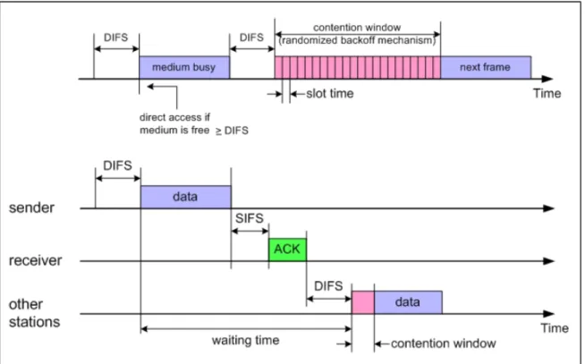
Since the CSMA/CA does not rely on the capability of the stations to detect a collision by hearing their own transmission, an ACK is transmitted by the destination station to signal the successful packet reception. The ACK is immediately transmitted at the end of the packet, after a period of time called Short Inter-Frame Space (SIFS). As the SIFS (plus the propagation delay) is shorter than a DIFS, no other station is able to detect the
channel idle for a DIFS until the end of the ACK. If the transmitting station does not receive the ACK within a specified ACK_Timeout, or it detects the transmission of a different packet on the channel, it reschedules the packet transmission according to the given backoff rules.
The above described two-way handshaking technique for the packet transmission is called basic access mechanism and is shows in Figure 9.
Figure 9: Basic access mechanism used in DCF
DCF defines an additional four-way handshaking technique to be optionally used for a packet transmission. This mechanism is also known with the name RTS/CTS. This optional mechanism is very useful for solving hidden/exposed terminal problems that are common in ad hoc networks.
A station that wants to transmit a packet, waits until the channel is sensed idle for a DIFS, follows the backoff rules explained above, and then, instead of the packet, preliminarily transmits a special short frame called request to send (RTS). When the receiving station detects an RTS frame, it responds, after a SIFS, with a clear to send (CTS) frame. The transmitting station is allowed to transmit its packet only if the CTS frame is correctly received.
The frames RTS and CTS carry the information of the length of the packet to be transmitted. This information can be read by any listening station, which is then able to update a Network Allocation
Vector (NAV) containing the information of the period of time in which the channel will remain busy. Therefore, when a station is hidden from either the transmitting or the receiving station, by detecting just one frame among the RTS and CTS frames, it can suitably delay further transmission, and thus avoid
collision.
POINT COORDINATION FUNCTION (PCF)
PCF is an alternative access method; it uses a Point Coordinator (PC) and it’s built on top of the DCF.
It is a polling-based method.
The point coordinator makes use of Point coordinator function IFS (PIFS) when issuing polls.
Because PIFS is smaller than DIFS, the point coordinator can size the medium and lock out all asynchronous traffic while it issues polls and receives responses. If the discipline of the preceding paragraph were implemented, the point coordinator would lock out all asynchronous traffic by repeatedly issuing polls. To prevent this, an interval known as the super frame is defined. During the first part of this interval, the point coordinator issues polls in a round robin fashion to all stations configured for polling. Then it idles for the remainder of the super frame, allowing a contention period for asynchronous access. At the end of the super frame interval, the point coordinator contends for accessing the medium using PIFS.
If the medium is idle, the point coordinator gains immediate access and a full super frame period follows. Other ways the point coordinator must wait until the medium is idle to gain access.
Figure 10: MAC timing
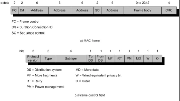
MAC FRAME
Figure 11 shows the 802.11 frame format. This is the format used for all data and control frames but not all fields are used in all contexts.
Figure 11: MAC frame
• Frame control: indicates the type of frame and provides control information.
• Duration/connection ID: if used as a duration field, indicates the time the channel will be
allocated for successful transmission of a MAC frame. In some control frames, this field contains an association or connection identifier.
• Addresses: the number and meaning of the address fields depend on the context. Address
types include source, destination, transmitting station and receiving station.
• Sequence control: contains 4-bit fragment number subfield used for fragmentation and
reassembly and a 12-bit sequence number used to number frames sent between a given transmitter and receiver.
• Frame body: contains an MSDU or a fragment of an MSDU. The MSDU is a LLC protocol
data unit or MAC control information.
• Frame check sequence: a 32-bit cyclic redundancy check.
The frame control field is built with the following fields:
• Protocol version: 802.11 version.
• Type: identifies the frame as control, management or data.
• Subtype: identifies the function of the frame.
• To DS: the MAC coordinator sets this bit to 1 in a frame destined to the distribution system.
• From DS: the MAC coordinator sets this bit to 1 in a frame leaving the distribution system.
• More fragments: set to 1 if more fragments follow this one.
• Retry: set to 1 if this is a retransmission of a previous frame
• Power management: set to 1 if the transmitting station is in a sleep mode.
• More data: indicates that a station has additional data to send.
• WEP: set to 1 if the optional wired equivalent protocol is implemented.
• Order: set to 1 in any data frame sent using Strictly Ordered service, which tells the receiver
that the frames must be processed in order.
MAC frames can be divided in three groups: control frames, management frames and data frames.
1) Control Frames
Control frames assist in the reliable delivery of data frames.
• Power save-poll (PS-Poll): this frame is sent by any station to the station that includes the AP.
Its goal is to request that the AP transmit a frame that has been buffered for this station while the station was in power-saving mode.
• Request To Send (RTS): the station sending this message alerts all other stations that it
intends sending a data frame to a certain destination.
• Clear To Send (CTS): it is sent by the destination station to the source station to grant
permission to send a data frame.
• Acknowledgement: provides an acknowledgement from the destination to the source.
• Contention-free (CF)-end: announces the end of a contention free period.
• CF-end + CF-ack: this frame ends the contention-free period and releases stations from the
restrictions associated with that period.
2) Data Frames
• Data: the simplest data frame.
• Data + CF-Ack: may only be sent during a contention-free period. In addition to carry data,
this frame acknowledges previously received data.
• Data + CF-Poll: used by a point coordinator to deliver data to a station and also to request that
the station send a data frame that it may have buffered.
• Data + CF-Ack + CF-Poll: combines the functions of the two previous frames.
• Null Function: it carries no data, no acknowledgements and no polls. It is used only to
indicate that a station is changing to a low-power operating state.
• CF-Ack: it has the same functionality as the corresponding data frame but without the data.
• CF-Poll: it has the same functionality as the corresponding data frame but without the data.
• CF-Ack + CF-Poll: it has the same functionality as the corresponding data frame but without
the data.
3) Management Frames
Management Frames are used to manage communications between stations and AP.
• Association request: sent by a station to an AP to request an association with this BSS; in it its
included information about whether encryption is to be used and whether this station is pollable.
• Association response: returned by the AP to the station to indicate whether it is accepting this
association request.
• Reassociation request: sent by a station when it moves from one BSS to another and needs to
make an association with the AP in the new BSS.
• Reassociation response: returned by the AP to the station to indicate whether it is accepting
this reassociation request.
• Probe request: used by a station to obtain information from another station or AP; it is usually
used to locate an IEEE 802.11 BSS.
• Probe response: response to a probe request.
• Beacon: transmitted periodically to allow mobile stations to locate
• and identify a BSS.
• Announcement traffic indication message: sent by a station to alert other stations that may
have been in low power mode that this station has frame buffered and waiting to be delivered.
• Disassociation: used by a station to terminate an association.
• Authentication: multiple authentication frames are used in an exchange to authenticate one
station to another.
• Deauthentication: sent by a station to another station or AP to indicate that is terminating
secure communications.
SECURITY: THE WEP PROTOCOL
Because wireless is a shared medium, everything that is transmitted or received over a wireless network can be intercepted. Encryption and authentication are always considered when developing a wireless networking system.
The goal of adding these security features is to make wireless traffic as secure as wired traffic.
The IEEE 802.11 standard provides a mechanism to do this by encrypting the traffic and
authenticating nodes via the Wired Equivalent Privacy (WEP) protocol. To provide privacy, as well as data integrity, WEP uses an encryption algorithm based on the RC4 encryption algorithm. The WEP algorithm is used to protect wireless communication from eavesdropping. A secondary function of WEP is to prevent unauthorized access to a wireless network; this function is not an explicit goal in the 802.11 standard, but it s frequently considered to be a feature of WEP.
WEP relies on a secret key that is shared between a mobile station (e.g. a laptop with a wireless
ethernet card) and an access point (e.g. a base station). The secret key is used to encrypt packets before they are transmitted, and an integrity check is used to ensure that packets are not modified in transit. The standard does not discuss how the shared key is established. In practice, most installations use a single key that is shared between all mobile stations and access points. More sophisticated key management techniques can be used to help defend from the attacks.
Encryption of a frame
Two processes are applied to the plaintext data. One encrypts the plaintext; the other protects against unauthorized data modification.
The secret key (40-bits) is concatenated with an initialization vector (IV, 24-bits) resulting in a 64-bit total key size. The resulting key is input into the PseudoRandom Number Generator (PRNG). The PRNG, using RC4, outputs a pseudorandom key sequence based on the input key. The resulting sequence is used to encrypt the data by doing a bitwise XOR. This results in encrypted bytes equal in length to the number of data bytes that are to be transmitted in the expanded data plus 4 bytes. This is because
the key sequence is used to protect the Integrity Check Value (ICV, 32-bits) as well as the data. To protect against unauthorized data modification, an integrity algorithm (CRC-32) operates on the plaintext to produce the ICV.
Figure 12: WEP encryption
The ciphertext is accomplished by doing the following steps as shown in Figure 13.
1. Compute the ICV using CRC-32 over the message plaintext.
2. Concatenate the ICV to the plaintext.
3. Choose a random initialization vector (IV) and concatenate this to the secret key.
4. Input the secret key+IV into the RC4 algorithm to produce a pseudorandom key sequence.
5. Encrypt the plaintext+ICV by doing a bitwise XOR with the pseudorandom key sequence
under RC4 to produce the ciphertext.
6. Communicate the IV to the peer by placing it in front of the ciphertext. The IV, plaintext,
and ICV triplet forms the actual data sent in the data frame.
Decryption of a frame
In decryption, the IV of the incoming message is used to generate the key sequence necessary to decrypt the incoming message (see figure 13). Combining the ciphertext with the proper key sequence yields the original plaintext and ICV.
The decryption is verified by performing the integrity check algorithm on the recovered plaintext and comparing the output ICV0 to the ICV transmitted with the message. If ICV0 is not equal to ICV, the received message is in error, and an error indication is sent to the MAC
management and back to the sending station.
Mobile units with erroneous messages (due to inability to decrypt) are not authenticated.
Figure 13: Block diagrams for WEP encryption and decryption
AUTHENTICATION
The same shared key used to encrypt/decrypt the data frames is also used to authenticate the station.
It is considered a security risk to have the encryption and authentication keys be the same. IEEE 802.11 provides two types of authentication: Open System Authentication and Shared Key System.
Open system authentication simply provides a way for two parties to agree to exchange data and provides no security benefits. In open system authentication, one party sends a MAC control frame, known as an authentication frame, to the other party. The frame indicates that this is an open system authentication type. The other party responds with its own authentication frame and the process is complete. Thus, open system authentication consists simply of the exchange of identities between the parties and provides ”null” authentication. The station can associate with any access point and listen to all data that are sent plaintext.
Shared key authentication requires that two parties share a secret key not shared by any other party.
This key is used to assure that both sides are authenticated to each other.
Figure 14 illustrates the operation of sharedkey authentication. The secret shared key resides in each station’s MIB in a write-only form and is therefore only available to the MAC coordinator. The 802.11 standard does not specify how to distribute the keys to each station, however.
The process is as follows:
1. A requesting station sends an Authentication Request frame to the access point.
2. When the AP receives an initial Authentication Request frame, it will reply with an
Authentication frame containing 128 bytes of random ”challenge text” generated by the WEP engine in standard form.
3. The requesting station will then copy the challenge text into an Authentication frame, encrypt it with a shared key, and then send the Challenge Response frame to the responding station.
4. The receiving AP will decrypt the value of the challenge text using the same shared key and compare it to the challenge text sent earlier. If a match occurs, the AP will reply with a frame indicating a successful authentication. If not, the responding AP will send a negative
authentication.
Figure 14: Shared key authentication
PHYSICAL LAYER
The physical layer for IEEE 802.11 has been developed in three stages; the first part was issued in 1997 and the remaining two parts in 1999.
The first part, called IEEE 802.11, includes the MAC layer and three physical layer specifications:
• Direct-sequence spread spectrum operating in the 2.4 GHz ISM band, at data rates of 1 Mbps
and 2 Mbps.
• Frequency-hopping spread spectrum operating in the 2.4 GHz ISM band, at data rates of 1
Mbps and 2 Mbps.
• Infrared at 1Mbps and 2 Mbps operating at a wavelength between 850 and 950 nm.
The other two layers developed in 1999 are IEEE 802.11a that operates in the 5 GHz band at data rates up to 54 Mbps and IEEE 802.11b that operates in the 2.4 GHz band at 5.5 and 11 Mbps.
Further standards were developed in the following years but in our discussion we will focus only on the IEEE 802.11b physical layer.
Figure 15: IEEE 802.11 PHY layer
INTRODUCTION
IEEE 802.11 specifies a 2.4 GHz operating frequency with data rates of 1 and 2 Mbps using either Direct Sequence Spread Spectrum (DSSS) or Frequency Hopping Spread Spectrum (FHSS).
In IEEE 802.11b data is encoded using DSSS technology. DSSS works by taking a data stream of zeros and ones and modulating it with a second pattern, the chipping sequence. In 802.11, that sequence is known as the Barker code, which is an 11 bits sequence (10110111000) that has certain mathematical properties making it ideal for modulating radio waves.
A Barker sequence is a binary {-1,+1} sequence s(t) of length n with the property that its
autocorrelation values R(τ ) satisfy |R(τ )| ≤ 1 for all |τ | ≤ (n − 1). Further, the Barker property is preserved under the following transformations.
s(t) ! −s(t) s(t) ! (−1)t s(t) and s(t) ! −s(n − 1 − t) as well as under compositions of these transformations.
Only the following Barker sequence are known:
n = 2 ++
n = 3 + + − n = 4 + + +−
n = 5 + + + − + n = 7 + + + − − + −
n = 11 + − + + − + + + − − − n = 13 + + + + + − − + + − + − +
The 11-chip Barker sequence is used. Thus, each data binary
1 is mapped into the sequence {+−++−+++−−−}, and each 0 is mapped into the sequence {− + − − + − − − + + +}.
Important characteristic of Barker sequences are their robustness against interference and their insensitivity to multipath propagation.
The basic data stream is XOR’d with the Barker code to generate a series of data objects called chips.
Each bit is ”encoded” by the 11bits Barker code, and each group of 11 chips encodes one bit of data.
IEEE 802.11b uses 64 CCK (Complementary Code Keying) chipping sequences to achieve 11 Mbps.
Rather than using the Barker code, CCK uses a series of codes called Complementary Sequences.
Because there are 64 unique code words that can be used to encode the signal, up to 6 bits can be represented by any one particular code word (instead of the 1 bit represented by a Barker symbol).
The wireless radio generates a 2.4 GHz carrier wave (2.4 to 2.483 GHz) and modulates that wave using a variety of techniques. For 1 Mbps transmission, BPSK (Binary Phase Shift Keying) is used (one phase shift for each bit). To accomplish 2 Mbps transmission, QPSK (Quadrature Phase Shift Keying) is used.
QPSK uses four rotations (0, 90, 180 and 270 degrees) to encode 2 bits of information in the same space as BPSK encodes 1. The trade-off is increase power or decrease range to maintain signal quality.
Because the FCC regulates output power of portable radios to 1 watt EIRP (Equivalent Isotropic Radiated Power), range is the only remaining factor that can change. On 802.11 devices, as the
transceiver moves away from the radio, the radio adapts and uses a less complex (and slower) encoding mechanism to send data.
The MAC layer communicates with the PLCP (Physical Layer Convergence Protocol ) via specific primitives through a PHY (Physical Layer) service access point. When the MAC layer instructs, the PLCP prepares MPDUs (MAC Protocol Data Units) for transmission. The PLCP also delivers incoming frames from the wireless medium to the MAC layer. The PLCP sublayer minimizes the dependence of the MAC layer on the PMD sublayer by mapping MPDUs into a frame format suitable for transmission by the PMD (Physical Medium Dependent).
Under the direction of the PLCP, the PMD provides actual transmission and reception of PHY entities between two stations through the wireless medium. To provide this service, the PMD interfaces directly with the air medium and provides modulation and demodulation of the frame transmissions. The PLCP and PMD communicate using service primitives to govern the transmission and reception functions.
The CCK code word is modulated with the QPSK technology used in 2 Mbps wireless DSSS radios.
This allows for an additional 2 bits of information to be encoded in each symbol. Eight chips are sent for each 6 bits, but each symbol encodes 8 bits because of the QPSK modulation. The spectrum math for 1 Mbps transmission works out as 11 Mchips per second times 2 MHz equals 22 MHz of spectrum.
Likewise, at 2 Mbps, 2 bits per symbol are modulated with QPSK, 11 Mchips per second, and thus have 22 MHz of spectrum. To send 11 Mbps 22 MHz of frequency spectrum is needed.
It is much more difficult to discern which of the 64 code words is coming across the airwaves, because of the complex encoding. Furthermore, the radio receiver design is significantly more difficult. In fact, while a 1 Mbps or 2 Mbps radio has one correlator (the device responsible for lining up the various signals bouncing around and turning them into a bit stream), the 11 Mbps radio must have 64 such devices. Figure 16 shows the digital modulation of data with the PRN sequence.
The wireless physical layer is split into two parts, called the PLCP and the PMD sublayer. The PMD takes care of the wireless encoding. The PLCP presents a common interface for higher-level drivers to write to and provides
Figure 16: Digital modulation of data with PRN sequence
carrier sense and CCA (Clear Channel Assessment), which is the signal that the MAC layer needs so it can determine whether the medium is currently in use.
The PLCP consists of a 144 bits preamble that is used for synchronization to determine radio gain and to establish CCA. The preamble comprises 128 bits of synchronization, followed by a 16 bits field consisting of the pattern 1111001110100000. This sequence is used to mark the start of every frame and is called the SFD (Start Frame Delimiter).
The next 48 bits are collectively known as the PLCP header. The header contains four fields: signal, service, length and HEC (Header Error Check).
• The signal field indicates how fast the payload will be transmitted (1, 2, 5.5 or 11 Mbps).
• The service field is reserved for future use.
• The length field indicates the length of the ensuing payload.
• The HEC is a 16 bits CRC of the 48 bits header.
In a wireless environment, the PLCP is always transmitted at 1 Mbps. Thus, 24 bytes of each packet are sent at 1 Mbps. The PLCP introduces 24 bytes of overhead into each wireless Ethernet packet. Ethernet introduces only 8 bytes of data. Because the 192 bits header payload is transmitted at 1 Mbps, IEEE 802.11b is at best only 85
OVERVIEW
The IEEE 802.11b is a Direct Sequence Spread Spectrum (DSSS) system very similar in concept to the CDMA Wireless, using a spread spectrum chip sequence.
In the IEEE 802.11b the transmission medium is wireless and the operating frequency band is 2.4 GHz.
IEEE 802.11b provides 5.5 and 11 Mbps payload data rates in addition to the 1 and 2 Mbps rates provided by 802.11.
To provide the higher rates, 8 chip Complementary Code Keying (CCK) is employed as the modulation scheme. The CCK uses 6 bits to encode the code sent, this increase the speed of the 802.11 by 6.The chipping rate is 11 MHz, which is the same as the DSSS system as described in 802.11, thus providing the same occupied channel bandwidth.
IEEE 802.11b describes an optional mode replacing the CCK modulation with packet binary convolutional coding (HR/DSSS/PBCC).
Another optional mode of IEEE 802.11b allows data throughput at the higher rates (2, 5.5, and 11 Mbps) to be significantly increased by using a shorter PLCP preamble. This mode is called HR/DSSS/short. This Short Preamble mode can coexist with DSSS, HR/DSSS under limited circumstances, such as on different channels or with appropriate CCA mechanisms.
The High Rate PHY contains three functional entities: the PMD function, the physical layer convergence function, and the layer management function.
For the purposes of MAC and MAC Management when channel agility is both present and enabled, the High Rate PHY shall be interpreted to be both a High Rate and a frequency hopping physical layer. The High Rate PHY service shall be provided to the MAC through the PHY service primitives. To allow the MAC to operate with minimum dependence on the PMD sublayer, a physical layer convergence
procedure (PLCP) sublayer is defined. This function simplifies the PHY service interface to the MAC services.
The PMD sublayer provides a means and method of transmitting and receiving data through a wireless medium (WM) between two or more STAs each using the High Rate system.
The PLME performs management of the local PHY functions in conjunction with the MAC management entity.
CCK
CCK is a variation on M-ary Orthogonal Keying modulation, which uses I/Q modulation architecture with complex symbol structures. CCK allows for multi-channel operation in the 2.4 GHz band using the existing 802.11 DSSS channel structure scheme. The spreading employs the same chipping rate and spectrum shape as the 802.11 Barker’s code word. Spreading functions, allows three non-interfering channels in the 2.4 to 2.483 GHz band.
CCK is an M-ary Orthogonal Keying modulation where one of M unique (nearly orthogonal) signal codewords is chosen for transmission. The spread function for CCK is chosen from a set of M nearly orthogonal vectors by the data word. CCK uses one vector from a set of 64 complex (QPSK) vectors for the symbol and thereby modulates 6 bits (one of 64) on each 8 chips spreading code symbol. Two more bits are sent by QPSK modulating the whole code symbol. This results in modulating 8 bits onto each symbol. The formula that defines the CCK codewords has 4 phase terms.
One of them modulates all of the chips (φ1) and this is used for the QPSK rotation of the whole code vector.
The 3 others modulate every odd chip (φ2), every odd pair of chips (φ3) and every odd quad of chips (φ4) respectively.
Walsh functions used for the M-ary Bi-Orthogonal keying (MBOK) modulation are the most well known orthogonal BPSK vector set. To transmit enough bits per symbol, the MBOK modulation is used independently on the I and Q channels of the waveform effectively doubling the data rate. CCK on the other hand uses a complex set of Walsh/Hadamard functions known as Complementary Codes.
Walsh/Hadamard properties are similar to Walsh functions but are complex, that is, more than two phase, while still being nearly orthogonal. With complex code symbols, it is not possible to
independently transmit simultaneous code symbols without suffering amplitude modulation. Since the set of complementary codes is more extensive, however, we have a larger set of nearly orthogonal codes to pick from and can get the same number of bits transmitted per symbol without simultaneous
transmission of symbols.
The multi-path performance of CCK is better than MBOK due to the lack of cross rail interference. For MBOK, there are 8 BPSK chips that have a maximum vector space of 256 code words of which it is possible to find sets of 8 that are orthogonal. Two independent BPSK vector sets are selected for the orthogonal I and Q channels which modulate 3 bits on each.
Two additional bits are used to BPSK modulate each of the spreading code vectors. For CCK, there are 65536 possible code words, and sets of 64 that are nearly orthogonal. This is because it really takes 16 bits to define each code vector. To get a half data rate version, a subset of 4 of the 64 vectors having superior coding distance is used.
CCK suffers less from multi-path distortion in the form of cross coupling (of I and Q channel information) than MBOK. The information in CCK is encoded directly onto complex chips, which cannot be cross-couple corrupted by multi-path since each channel finger has an AejЂdistortion. A single channel path gain-scales and phase-rotates the signal. A gain scale and phase rotation of a complex chip still maintains I/Q orthogonal. This superior encoding technique avoids the corruption resulting from encoding half the information on the I-channel and the other half on the Q-channel, as in MBOK, which easily cross-couple corrupts with the multipath’s Aej# phase rotation.
For 1 Mbps, the signal is modulated BPSK by one bit per symbol and then spread by BPSK modulating with the 11 chip Barker code at 11 Mbps.
For 2 Mbps, the signal is QPSK modulated by two bits per symbol and then BPSK spread as before. For the 5.5 Mbps CCK mode, the incoming data is grouped into 4 bits nibbles where 2 of those bits select
the spreading function out of the set of 4 while the remaining 2 bits QPSK modulate the symbol.
The spreading sequence then DQPSK modulates the carrier by driving the I and Q modulators. To make 11 Mbps CCK modulation, the input data is grouped into 2 bits and 6 bits. The 6 bits are used to select one of 64 complex vectors of 8 chip length for the symbol and the other 2 bits DQPSK modulate the entire symbol. The chipping rate is maintained at 11 Mbps for all modes.
The signal acquisition scheme for 802.11 uses a specific preamble and header using the 1 Mbps
modulation and has provision for sending the payload at different rates. The packet frame structure and protocol of 802.11 is much like 802.3 Ethernet, however it must operate wirelessly in a harsh RF environment. This means that the signal levels may become corrupted and subject to multi-path. Signal acquisition and synchronization of the preamble and header are critical. The preamble and header consists of six
fields. They are: Preamble, SFD, Signal (rate), Service, Length and CRC.
The header takes 48 bits, and the total length of the acquisition sequence is 192 µs. The preamble and header is modulated using the 1 Mbps modulation rate and is scrambled with a self-synchronizing scrambler. The high rate scheme will use this acquisition sequence, which already has a rate field that can be programmed for 1, 2, 5.5 or 11 Mbps.
The 802.11 packet transmission protocol is Carrier Sense Multiple Access with Collision Avoidance (CSMA/CA). This differs from ”wired” Ethernet, which uses collision detection. Radios can’t detect collisions, therefore they use collision avoidance using a listen before talk and random back off deferral mechanism. Since all stations use the same acquisition sequence at the lowest basic rate, all stations can see the traffic and process the signals at the appropriate rate. If legacy 1 and 2 Mbps stations receive the packet header, but are not capable of processing the higher rate, they can still defer the medium based on knowing that an 802.11 signal has been sensed and knowing the length of time it will be on the air.
To insure that the modulation has the same bandwidth as the existing 802.11 DS modulation, the
chipping rate is kept at 11 Mbps while the symbol rate is increased to 1.375 MSps. This accounts for the shorter symbols and makes the overall bit rate 11 Mbps. This approach makes system interoperability with the 802.11 preamble and header much easier. The spread rate remains constant and only the data rate changes and the spectrum of the CCK waveform is same as the legacy 802.11 waveform.
WALSH AND COMPLEMENTARY CODES
Walsh codes can be obtained performing simple operations as it is illustrated in Figure 17. For the 2-ary case, taking a 2x2 matrix of 1s and inverting the lower right quadrant of the matrix form the basic symbols. To form the 4-ary case, take 4 of the 2x2 matrices and make a 4x4 matrix with the lower right hand quadrant again inverted. The procedure is repeated for the 8-ary case and beyond.
Figure 17: Forming Walsh Codes by successive folding
Walsh functions have a regular structure and at least one member that has a substantial DC bias. In this case it is the first row with all 1s. All the rest are half 1s and half 0s. The DC bias can be reduced on the worst member of the set by multiplying all members with a cover code. This, however, introduces a (smaller) bias in half of the members.
The main concern about MBOK is caused by the fact that it uses independent codes on the in phase and quadrature signals, which creates a significant amount of cross rail interference in the presence of multipath.
To avoid this, one would ideally transmit only symbols for which processing could be done on I and Q simultaneously, and use code words that all have good autocorrelation properties, such that there is minimal inter-symbol and inter-chip interference. Such codes actually exist in the form of the complementary codes. For a code length of 8 chips, 256 possible sequences c can be constructed as follows, using 4 QPSK phases '1 to '4. Note that '1 is presented in all 8 chips, so it simply rotates the entire code word. Hence, to decode these codes set, one would need 64 correlators plus an additional
phase detection of the code that gave the largest correlation output. The correlation can be significantly simplified by using techniques like the Fast Walsh transform (analogous to an FFT butterfly circuit). In fact, when the 4 input phases '1 to '4 are binary, then the complementary code set reduces to a modified Walsh code set.
FAST TRANSFORM STRUCTURE
The four-phase variables each take on values of [0, _/2, _ , 3_/2], and there are 256 (4*64) possible 8 chip codes. These codes have an inherent ”Walsh” type structure that allows a simple butterfly
implementation of the decoder. Although it is possible to squeeze a few more complementary codes out of this 8 chips set, the rest of the codes cannot be decoded with the modified fast Walsh transform.
Figure 18 shows the basic fast Walsh block which brings in 8 chips of soft decision data shown here by x0, x1, . . . x7, and produces 16 possible correlation for given values of '1 and '2 . Figure 19
shows all 256 possible correlator outputs. The BFWB’s are shown in detail in Figure 18. There are 28 butterflies needed for a length 8 transform.
Each butterfly requires 4 additions (the phase rotations are trivial for 4- PSK), so the total number of operations is 112 complex additions. The direct calculation method with 64 separate correlators requires 512 complex additions, so the fast transform reduces the complexity by almost a factor of 5.
CCK is inherently a quadrature MOK signal. For the full data rate potential, DQPSK modulate the starting phase of the symbols to get 11 Mbps. To reduce the data rate for a more robust lower data rate, we can trim the signal set to one that has the greatest distance properties with a reduced number of vectors.
Figure 18: Basic Fast Walsh Transform Block (BFWB)
For 5.5 Mbps, there are two options
• First, trim the 64-ary set to 8-ary and BPSK modulate the symbols
• Second, trim the set to 4-ary and QPSK modulate the symbols.
Either scheme achieves 4 bits per symbol but simulations conclude that the latter is more robust in multipath.
The excellent range that the CCK modulation achieves is due to the fact that MOK has better Eb/No performance than BPSK. This performance is due the embedded coding properties of the spreading modulation. The modulation basically ties several bits together so that the receiver makes a symbol decision. If a symbol is in error then all of the bits in that symbol are suspect, but not all will necessarily be in error. Thus, the symbol error rate and the bit error rates are related. While the SNR required making a symbol decision correctly is higher than required to make a one-bit decision, it is not
as high as required to make all of the bit decisions of a symbol independently and correctly. Thus, some coding gain is embedded in the basic spreading waveform. Simulations conclude that the high rates are
more susceptible to multi-path than the lower rates as would be expected from the higher required Es/No.
Figure 19: Modified Walsh Transform