Distributed Systems in practice HS 2007
Gustavo Alonso
Institute for Pervasive Computing Computer Science Department
Swiss Federal Institute of Technology (ETHZ) alonso@inf.ethz.ch
http://www.iks.inf.ethz.ch/
©IKS, ETH Zürich. 2
Distributed systems in practice
Motivation and examples
¾Enterprise computing / Enterprise Architecture
¾Modern distributed systems
2 Phase Commit – Transactions (Dec. 3, 2007)
¾Transactional exchanges
¾2PC
¾3PC
Data Replication (Dec. 10, 2007)
¾Data replication models
¾Data replication systems
Web services (Dec. 17, 2007)
¾SOAP, WSDL, UDDI / Service Oriented Architecture
©IKS, ETH Zürich. 3
and as a complement …
Building a distributed system with embedded devices and sensors
¾René Müller (Dec 7., 2007)
Modular architectures and distribution
¾Jan Rellermeyer (Dec. 14., 2007)
Exercises (paper) will be distributed during the
lecture - due one week later
©IKS, ETH Zürich. 4
References
References to use (and read):
¾For 2PC and 3PC
• Concurrency Control and Recovery in Database Systems (Bernstein, Hadzilacos, Goodman)
http://research.microsoft.com/~philbe/ccontrol/¾For replication: same & slides
¾For web services: slides and supporting material
©IKS, ETH Zürich. 5
A prelude to
Courses in the Distributed Systems Master Track:
¾Enterprise Application Integration
¾Web Services and Service Oriented Architectures
¾Distributed algorithms
¾Sensor networks
¾P2P systems
¾…
Motivation and examples
Enterprise Architecture
©IKS, ETH Zürich. 7
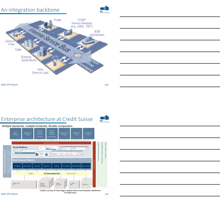
Enterprise architecture at Credit Suisse
Multiple backends, multiple frontends, flexible composition
Graphic courtesy of Claus Hagen, Stephen Murer and Hanspeter Uebelbacher of Credit Suisse
©IKS, ETH Zürich. 8
Understanding the layers
To support a client, the system needs to have a presentation layer through which the user can submit operations and obtain a result.
The application logic establishes what operations can be performed over the system and how they take place. It takes care of enforcing the business rules and establish the business processes.
The resource manager deals with the organization (storage, indexing, and retrieval) of the data necessary to support the application logic. This is typically a database but it can also be any other data management system.
Presentation logic Application Logic Resource Manager
2-5 years Application (system’slogic) 1-2 years Clients and External interface
(presentation, access channels)
~10 years Data management systems (operational and strategic data)
©IKS, ETH Zürich. 9
INTEGRATION TIER ACCESS TIER
CLIENT TIER
RESOURCE TIER APP TIER
wrapper wrapper
wrapper
db db db
business
object business
object business
object api api api web client
java client wap client
web servers, J2EE, CGI JAVA Servlets API web servers, J2EE, CGI
JAVA Servlets API
databases, multi-tier systems backends, mainframes databases, multi-tier systems
backends, mainframes system federations, filters
object monitors, MOM system federations, filters
object monitors, MOM TP-Monitors, stored procedures
programs, scripts, beans TP-Monitors, stored procedures
programs, scripts, beans web and wap browsers specialized clients (Java, Notes)
SMS ...
web and wap browsers specialized clients (Java, Notes)
SMS ... CLIENTACCESSAPPINTEGRATIONRESOURCE HTML, SOAP, XML
MOM, HTML, IIOP, RMI-IIOP, SOAP, XML
MOM, IIOP, RMI-IIOP, XML
ODBC, JDBC, RPC, MOM, IIOP, RMI-IIOP
©IKS, ETH Zürich. 10
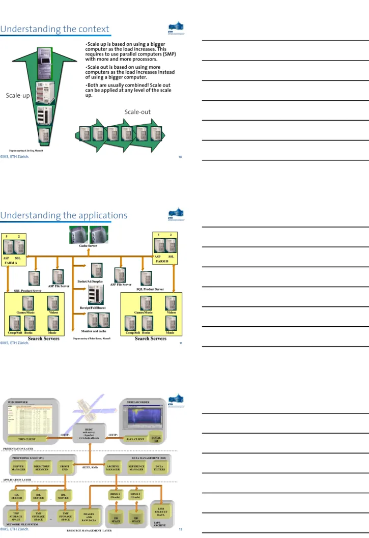
Understanding the context
Scale-up
Scale-out
Diagrams courtesy of Jim Gray, Microsoft
•Scale up is based on using a bigger computer as the load increases. This requires to use parallel computers (SMP) with more and more processors.
•Scale out is based on using more computers as the load increases instead of using a bigger computer.
•Both are usually combined! Scale out can be applied at any level of the scale up.
©IKS, ETH Zürich. 11
Understanding the applications
ASP ASP SSLSSL
FARM A FARM A
Games/Music Games/Music VideosVideos
Comp/Soft
Comp/SoftBooksBooks MusicMusic SQL Product Server SQL Product Server
ASP File Server ASP File Server
Cache Server Cache Server
Basket/Ad/Surplus Basket/Ad/Surplus
Receipt/Fulfillment Receipt/Fulfillment
Monitor and cache Monitor and cache
ASP ASP SSLSSL
FARM B FARM B
Games/Music Games/Music VideosVideos
Comp/Soft
Comp/SoftBooksBooks MusicMusic SQL Product Server SQL Product Server ASP File Server
ASP File Server
Search Servers
Search Servers Search ServersSearch Servers
55 2222 55 22
Diagram courtesy of Robert Barnes, Microsoft
©IKS, ETH Zürich. 12
PROCESSING LOGIC (PL) DATA MANAGEMENT (DM)
SERVER MANAGER
DIRECTORY SERVICES
DATA FILTERS REFERENCE
MANAGER
...
TMP STORAGE
SPACE IDL SERVER
TMP STORAGE
SPACE TMP STORAGE
SPACE IDL SERVER IDL
SERVER
...
IMAGES AND RAW DATA NETWORK FILE SYSTEM
DB SPACE
DB SPACE DBMS 1 (Oracle)
DBMS 2 (Oracle)
LESS RELEVAT
DATA
TAPE ARCHIVE FRONT
END
ARCHIVE MANAGER (HTTP, RMI) PRESENTATION LAYER
APPLICATION LAYER THIN CLIENT
(HTTP)
WEB BROWSER STREAMCORDER
(HTTP) HEDC web server
(Apache)
www.hedc.ethz.ch JAVA CLIENT LOCAL DB
©IKS, ETH Zürich. 13
Motivation and examples
Modern distributed systems
©IKS, ETH Zürich. 14
Distribution at the different layers
Presentation logic Application Logic Resource Manager Client/Server
Separated application logic Any combination thereof
Data distribution or replication
©IKS, ETH Zürich. 15
A game of boxes and arrows
Each box represents a part of the system.
Each arrow represents a connection between two parts of the system.
The more boxes, the more modular the system: more opportunities for distribution and parallelism. This allows encapsulation, component based design, reuse.
The more boxes, the more arrows:
more sessions (connections) need to be maintained, more coordination is necessary. The system becomes more complex to monitor and manage.
The more boxes, the greater the number of context switches and intermediate steps to go through before one gets to the data.
Performance suffers considerably.
System designers try to balance the capacity of the computers involved and the advantages and disadvantages of the different architectures.
There is no problem in system design that cannot be solved by adding a level of indirection.
There is no performance problem that cannot be solved
by removing a level of indirection.
©IKS, ETH Zürich. 16
Architectures (1): 1 tier architectures
The presentation layer, application logic and resource manager are built as a monolithic entity.
Users/programs access the system through display terminals but what is displayed and how it appears is controlled by the server. (This are the
“dumb” terminals).
This was the typical architecture of mainframe applications, offering several advantages:
¾no forced context switches in the control flow (everything happens within the system),
¾all is centralized, managing and controlling resources is easier,
¾the design can be highly optimized by blurring the separation between layers.
This is not as unfashionable as one may think: network computing is based on similar ideas!
1-tier architecture
Server
©IKS, ETH Zürich. 17
Architecture (2): 2 tier architectures
As computers became more powerful, it was possible to move the presentation layer to the client. This has several advantages:
¾Clients are independent of each other: one could have several presentation layers depending on what each client wants to do.
¾One can take advantage of the computing power at the client machine.
¾It introduces the concept of API (Application Program Interface).
An interface to invoke the system from the outside. It also allows to think about federating these systems by linking several of them.
¾The resource manager only sees one client: the application logic.
This greatly helps with performance since there are no connections/sessions to maintain.
2-tier architecture
Server
Architecture (3): 3 tier architectures
In a 3 tier system, the three layers are fully separated.
For some people, a middleware based system is a 3 tier architecture. This is a bit oversimplified but conceptually correct since the underlying systems can be treated as black boxes. In fact, 3 tier makes only sense in the context of middleware systems (otherwise the client has the same problems as in a 2 tier system!).
We will see examples of this architecture when concrete middleware systems are discussed.
A 3 tier systems has the same advantages as a middleware system and also its disadvantages.
In practice, things are not as simple as they seem … there are several hidden layers that are not necessarily trivial: the wrappers.
3-tier architecture
©IKS, ETH Zürich. 19
A real 3 tier middleware based system ...
External clients
connecting logic control
user logic internal
clients
2 tier systems
Resource managers wrappers
middleware
Resource manager 2 tier system
middleware system
External client
©IKS, ETH Zürich. 20
The Web as software layer ...
The WWW suddenly opened up software systems that had remained hidden within the IT organization of a company
It is not that new types of interactions were possible.
Behind the WWW there is the same client/server model as in basic RPC. However, the WWW made everything much easier, cheaper and efficient
¾integration at the level of user interface became possible
¾services could be accessed from anywhere in the world
¾the clients could now be not just an internal or selected user but anybody with a browser
Branch 1 Branch 2
app server 1 app server 1’
wrappers Front end
user program user program user program
user program MIDDLEWARE
WEB SERVER Browser
©IKS, ETH Zürich. 21
… on top of existing systems
Branch 1 Branch 2 Finance Dept.
Yearly balance ? Monthly
average revenue ?
app server 1 app server 1’
wrappers app server 2
app server 3 recoverable
queue Front end
user program user program user program
user program
Control (load balancing, cc and rec., replication, distribution, scheduling, priorities, monitoring …) TP-Monitor
environment
TP Client TP Client WEB SERVER
browser
Internet
CGI scrip calls
©IKS, ETH Zürich. 22
Business to Business (B2B)
Resource 1 Resource 2
Service 1 Service 2
wrappers Front end
user program user program user program
user program MIDDLEWARE
WEB SERVER FIREWALL
Resource X Resource Y
Service A Service B
wrappers Front end
user program user program user program
user program MIDDLEWARE
WEB SERVER
FIREWALL INTERNET
©IKS, ETH Zürich. 23
Motivation and examples
Basic middleware: RPC
One cannot expect the programmer to implement a complete infrastructure for every distributed application. Instead, one can use an RPC system (our first example of low level middleware)
What does an RPC system do?
¾Hides distribution behind procedure calls
¾Provides an interface definition language (IDL) to describe the services
¾Generates all the additional code necessary to make a procedure call remote and to deal with all the
communication aspects
¾Provides a binder in case it has a distributed name and directory service system
CLIENT
call to remote procedure
CLIENT stub procedure BindMarshalling
Send Communication
module Client process
Communication module Dispatcher
(select stub) SERVER stub procedure
Unmarshalling Return SERVER
remote procedure Server process
©IKS, ETH Zürich. 25
What can go wrong here?
INVENTORYCONTROL CLIENT Lookup_product Check_inventory IF supplies_low THEN
Place_order Update_inventory ...
Products database
DBMS Inventory
and order database
DBMS
New_product Lookup_product
Delete_product Update_product
Place_order Cancel_order Update_inventory
Check_inventory Server 3 (inventory) Server 2 (products)
RPC is a point to point protocol in the sense that it supports the interaction between two entities: the client and the server
When there are more entities interacting with each other (a client with two servers, a client with a server and the server with a database), RPC treats the calls as independent of each other.
However, the calls are not independent
Recovering from partial system failures is very complex. For instance, the order was placed but the inventory was not updated, or payment was made but the order was not recorded …
Avoiding these problems using plain RPC systems is very cumbersome
©IKS, ETH Zürich. 26
Transactional RPC
The limitations of RPC can be resolved by making RPC calls transactional. In practice, this means that they are controlled by a 2PC protocol
As before, an intermediate entity is needed to run 2PC (the client and server could do this themselves but it is neither practical nor generic enough)
This intermediate entity is usually called a
transaction manager (TM) and acts as intermediary in all interactions between
l d
database
DBMS client
server
database
DBMS server
TM
TM TM
TP monitor
XA XA
©IKS, ETH Zürich. 27
Basic TRPC (making calls)
Client BOT
… Service_call
…
Client stub Get tid from TM Add tid to call
Server
Service procedure Server stub
Get tid register with
the TM Invoke service return
Transaction Manager (TM) Generate tid
store context for tid Associate server to tid
1 2
3
4
5
©IKS, ETH Zürich. 28
Basic TRPC (committing calls)
Client ...
Service_call
… EOT
Client stub
Send to TM commit(tid)
Server Server stub
Participant in 2PC
Transaction Manager (TM) Look up tid
Run 2PC with all servers associated with tid Confirm commit 1
3 2
©IKS, ETH Zürich. 29
What we will see next
2 Phase Commit
Consistency across a distributed system (data replication)
Extending RPC/RMI to Internet scale systems
2PC-3PC:
Basics of transaction processing
©IKS, ETH Zürich. 31
Transaction Processing
Why is transaction processing relevant?
¾Most of the information systems used in businesses are transaction based (either databases or TP-Monitors). The market for transaction processing is many tens billions of dollars per year
¾Not long ago, transaction processing was used mostly in large companies (both users and providers). This is no longer the case (CORBA, WWW, Commodity TP-Monitors, Internet providers, distributed computing)
¾Transaction processing is not just database technology, it is core distributed systems technology
Why distributed transaction processing?
¾It is an accepted, proven, and tested programming model and computing paradigm for complex applications
¾The convergence of many technologies (databases, networks, workflow management, ORB frameworks, clusters of workstations …) is largely based on distributed transactional processing
©IKS, ETH Zürich. 32
From business to transactions
A business transaction usually involves an exchange between two or more entities (selling, buying, renting, booking …).
When computers are considered, these business transactions become electronic transactions:
The ideas behind a business transaction are intuitive. These same ideas are used in electronic transactions.
Electronic transactions open up many possibilities that are unfeasible with traditional accounting systems.
BUYER SELLER
TRANSACTION
STATE STATE STATE
book-keeping
©IKS, ETH Zürich. 33
The problems of electronic transactions
Transactions are a great idea:
Hack a small, cute program and that’s it.
Unfortunately, they are also a complex idea:
From a programming point of view, one must be able to encapsulatethe transaction (not everything is a transaction).
One must be able to run high volumesof these transactions (buyers want fast response, sellers want to run many transactions cheaply).
Transactions must be correct even if many of them are running concurrently(= at the same time over the same data).
Transactions must be atomic. Partially executed transactions are almost always incorrect (even in business transactions).
While the business is closed, one makes no money (in most business).
Transactions are “mission critical”.
Legally, most business transactions require a written record. So do electronic transactions.
©IKS, ETH Zürich. 34
What is a transaction?
Transactions originated as “spheres of control” in which to encapsulate certain behavior of particular pieces of code.
A transaction is basically a set of service invocations, usually from a program (although it can also be interactive).
A transaction is a way to help the programmer to indicate when the system should take over certain tasks (like semaphores in an operating system, but much more complicated).
Transactions help to automate many tedious and complex operations:
¾record keeping,
¾concurrency control,
¾recovery,
¾durability,
¾consistency.
It is in this sense that transactions are considered ACID (Atomic, Consistent, Isolated, and Durable).
©IKS, ETH Zürich. 35
Transactional properties
These systems would have been very difficult to build without the concept of transaction. To understand why, one needs to understand the four key properties of a transaction:
ATOMICITY: necessary in any distributed system (but also in centralized ones). A transaction is atomic if it is executed in its entirety or not at all.
CONSISTENCY: used in database environments. A transactions must preserve the data consistency.
ISOLATION: important in multi-programming, multi-user environments. A transaction must execute as if it were the only one in the system.
DURABILITY: important in all cases. The changes made by a transaction must be permanent (= they must not be lost in case of failures).
Transactional properties
consistent
database consistent
database Transaction
consistent
database inconsistent
database Txn
Failure
inconsistent database A
C
I
D
consistent
database consistent
database Txn
consistent
database consistent
database Txn 1
Txn 2
inconsistent database
system crash
recovery
recovery
©IKS, ETH Zürich. 37
Transactional atomicity
Transactional atomicity is an “all or nothing” property: either the entire transaction takes place or it does not take place at all.
A transaction often involves several operations that are executed at different times (control flow dependencies). Thus, transactional atomicity requires a mechanism to eliminate partial, incomplete results (arecovery protocol).
consistent
database inconsistent
database Txn
Failure RECOVERY
MANAGER
database log Txn
consistent
database inconsistent
database consistent
database
Failure
©IKS, ETH Zürich. 38
Transactional isolation
Isolation addresses the problem of ensuring correct results even when there are many transactions being executed concurrently over the same data.
The goal is to make transactions believe there is no other transaction in the system (isolation).
This is enforced by a concurrency controlprotocol, which aims at guaranteeing serializability.
consistent
database consistent
database Txn 1
Txn 2 inconsistent database
consistent database
Txn 1 Txn 2 consistent
database consistent
database Txn 1
Txn 2
CONCURRENCY CONTROL
©IKS, ETH Zürich. 39
Transactional consistency
Concurrency control and recovery protocols are based on a strong assumption: the transaction is always correct.
In practice, transactions make mistakes (introduce negative salaries, empty social security numbers, different names for the same person …).
These mistakes violate database consistency.
Transaction consistency is enforced through integrity constraints:
¾Null constrains: when an attribute can be left empty.
¾Foreign keys: indicating when an attribute is a key in another table.
¾Check constraints: to specify general rules (“employees must be either managers or technicians”).
Thus, integrity constraints acts as filters determining whether a transaction is acceptable or not.
NOTE: integrity constraints are checked by the system, not by the transaction programmer.
©IKS, ETH Zürich. 40
Transactional durability
Transactional system often deal with valuable information. There must be a guarantee that the changes introduced by a transaction will last.
This means that the changes introduced by a transaction must survive failures (if you deposit money in your bank account, you don’t want the bank to tell you they have lost all traces of the transaction because there was a disk crash).
In practice, durability is guaranteed by using replication: database backups, mirrored disks.
Often durability is combined with other desirable properties such as availability:
¾Availability is the percentage of time the system can be used for its intended purpose (common requirement: 99.86% or 1 hour a month of down time).
¾Availability plays an important role in many systems. Consider, for instance, the name server used in a CORBA implementation.
©IKS, ETH Zürich. 41
Atomic commitment:
2PC-3PC
Atomic Commitment
The Consensus
Problem
2 Phase Commit
3 Phase Commit
Applications
©IKS, ETH Zürich. 43
Atomic Commitment
Properties to enforce:
AC1 = All processors that reach a decision reach the same one (agreement, consensus).
AC2 = A processor cannot reverse its decision.
AC3 = Commit can only be decided if all processors vote YES (no imposed decisions).
AC4 = If there are no failures and all processors voted YES, the decision will be to commit (non triviality).
AC5 = Consider an execution with normal failures. If all failures are repaired and no more failures occur for sufficiently long, then all processors will eventually reach a decision (liveness).
©IKS, ETH Zürich. 44
Simple 2PC Protocol and its correctness
PROTOCOL:
Coordinator send VOTE-REQ to all participants.
Upon receiving a VOTE-REQ, a participant sends a message with YES or NO (if the vote is NO, the participant aborts the transaction and stops).
Coordinator collects all votes:
¾All YES = Commit and send COMMIT to all others.
¾Some NO = Abort and send ABORT to all which voted YES.
A participant receiving COMMIT or ABORT messages from the coordinator decides accordingly and stops.
CORRECTNESS:
The protocol meets the 5 AC conditions (I - V):
ACI = every processor decides what the coordinator decides (if one decides to abort, the coordinator will decide to abort).
AC2 = any processor arriving at a decision “stops”.
AC3 = the coordinator will decide to commit if all decide to commit (all vote YES).
AC4 = if there are no failures and everybody votes YES, the decision will be to commit.
AC5 = the protocol needs to be extended in case of failures (in case of timeout, a site may need to “ask around”).
©IKS, ETH Zürich. 45
Timeout Possibilities
COORDINATOR
send VOTE-REQ
wait for votes
send COMMIT
send ABORT
COMMIT
ABORT all vote YES
some vote NO
©IKS, ETH Zürich. 46
Timeout Possibilities
PARTICIPANT
wait for VOTE-REQ
wait for decision
ABORT
COMMIT vote YES
vote NO
ABORT received
COMMIT received
©IKS, ETH Zürich. 47
Timeout and termination
In those three waiting periods:
If the coordinator times-out waiting for votes: it can decide to abort (nobody has decided anything yet, or if they have, it has been to abort)
If a participant times-out waiting for VOTE-REQ: it can decide to abort (nobody has decided anything yet, or if they have, it has been to abort)
If a participant times-out waiting for a decision: it cannot decide anything unilaterally, it must ask (run a Cooperative Termination Protocol). If everybody is in the same situation no decision can be made: all processors will block.
This state is called uncertainty period
When in doubt, ask. If anybody has decided, they will tell us what the decision was:
There is always at least one processor that has decided or is able to decide (the coordinator has no uncertainty period). Thus, if all failures are repaired, all processors will eventually reach a decision
If the coordinator fails after receiving all YES votes but before sending any COMMIT message:
all participants are uncertain and will not be able to decide anything until the coordinator recovers. This is the blocking behavior of 2PC (compare with the impossibility result discussed previously)
Recovery and persistence
Processors must know their state to be able to tell others whether they have reached a decision. This state must be persistent:
Persistence is achieved by writing a log record. This requires flushing the log buffer to disk (I/O).
This is done for every state change in the protocol.
This is done for every distributed transaction.
This is expensive!
When sending VOTE-REQ, the coordinator writes a START-2PC log record (to know the coordinator).
If a participant votes YES, it writes a YES record in the log BEFORE it send its vote.
If it votes NO, then it writes a NO record.
If the coordinator decides to commit or abort, it writes a COMMIT or ABORT record before sending any message.
After receiving the
coordinator’s decision, a
participant writes its own
decision in the log.
©IKS, ETH Zürich. 49
Linear 2PC
Linear 2PC commit exploits a particular network configuration to minimize the number of messages:
YES
...
YES
YES
COM
©IKS, ETH Zürich. 50
Linear 2PC
The total number of messages is 2n instead of 3n, but the number of rounds is 2n instead of 3
YES
YES
NO NO
NO NO
©IKS, ETH Zürich. 51
3 Phase Commit Protocol
2PC may block if the coordinator fails after having sent a VOTE-REQ to all processes and all processes vote YES. It is possible to reduce the window of vulnerability even further by using a slightly more complex protocol (3PC).
In practice 3PC is not used. It is too expensive (more than 2PC) and the probability of blocking is considered to be small enough to allow using 2PC instead.
But 3PC is a good way to understand better the subtleties of atomic commitment
We will consider two versions of 3PC:
One capable of tolerating only site failures (no communication failures). Blocking occurs only when there is a total failure (every process is down). This version is useful if all participants reside in the same site.
One capable of tolerating both site and communication failures (based on quorums). But blocking is still possible if no quorum can be formed.
©IKS, ETH Zürich. 52
Blocking in 2PC
Why does a process block in 2PC?
If a process fails and everybody else is uncertain, there is no way to know whether this process has committed or aborted (NOTE: the coordinator has no uncertainty period. To block the coordinator must fail).
Note, however, that the fact that everybody is uncertain implies everybody voted YES!
Why, then, uncertain processes cannot reach a decision among themselves?
The reason why uncertain process cannot make a decision is that being uncertain does not mean all other processes are uncertain.
Processes may have decided and then failed. To avoid this situation, 3PC enforces the following rule:
NB rule: No operational process can decide to commit if there are operational processes that are uncertain.
How does the NB rule prevent blocking?
©IKS, ETH Zürich. 53
Avoiding Blocking in 3PC
The NB rule guarantees that if anybody is uncertain, nobody can have decided to commit. Thus, when running the cooperative termination protocol, if a process finds out that everybody else is uncertain, they can all safely decide to abort.
The consequence of the NB rule is that the coordinator cannot make a decision by itself as in 2PC. Before making a decision, it must be sure that everybody is out of the uncertainty area. Therefore, the coordinator, must first tell all processes what is going to happen: (request votes, prepare to commit, commit). This implies yet another round of
messages!
3PC Coordinator
bcast
vote-req wait for votes
ABORT
COMMIT bcast
commit
bcast abort bcast
pre-commit
wait for ACKs *
Possible time-out actions all vote YES
some vote NO
all ACKs
received
©IKS, ETH Zürich. 55
3PC Participant
wait for vote-req
ABORT
COMMIT wait for
pre-commit
send ACK
wait for commit
Possible time-out actions vote YES
abort received vote NO
pre-commit received
commit received
©IKS, ETH Zürich. 56
3PC and Knowledge (using the NB rule)
3PC is interesting in that the processes know what will happen before it happens:
Once the coordinator reaches the
“bcast pre-commit”, it knows the decision will be to commit.
Once a participant receives the pre-commit message from the coordinator, it knows that the decision will be to commit.
Why is the extra-round of messages useful?
The extra round of messages is used to spread knowledge across the system. They provide information about what is going on at other processes (NB rule).
The NB rule is used when time-outs occur (remember, however, that there are no communication failures):
If coordinator times out waiting for votes = ABORT.
If participant times out waiting for vote-req = ABORT.
If coordinator times out waiting for ACKs = ignore those who did not sent the ACK! (at this stage everybody has agreed to commit).
If participant times out waiting for pre-commit = still in the uncertainty period, ask around.
If participant times out waiting for commit message = not uncertain any more but needs to ask around!
©IKS, ETH Zürich. 57
Persistence and recovery in 3PC
Similarly to 2PC, a process has to remember its previous actions to be able to participate in any decision. This is accomplished by recording every step in the log:
Coordinator writes “start-3PC”
record before doing anything. It writes an “abort” or “commit”
record before sending any abort or commit message.
Participant writes its YES vote to the log before sending it to the coordinator. If it votes NO, it writes it to the log after sending it to the coordinator. When reaching a decision, it writes it in the log (abort or commit).
Processes in 3PC cannot independently recover unless they had already reached a decision or they have not participated at all:
If the coordinator recovers and finds a “start 3PC” record in its log but no decision record, it needs to ask around to find out what the decision was. If it does not find a
“start 3PC”, it will find no records of the transaction, then it can decide to abort.
If a participant has a YES vote in its log but no decision record, it must ask around. If it has not voted, it can decide to abort.
©IKS, ETH Zürich. 58
Termination Protocol
Elect a new coordinator.
New coordinator sends a “state req” to all processes. participants send their state (aborted, committed, uncertain, committable).
TR1 = If some “aborted” received, then abort.
TR2 = If some “committed”
received, then commit.
TR3 = If all uncertain, then abort.
TR4 = If some “committable” but no “committed” received, then send “PRE-COMMIT” to all, wait for ACKs and send commit message.
TR4 is similar to 3PC, have we actually solved the problem?
Yes, failures of the participants on the termination protocol can be ignored. At this stage, the coordinator knows that everybody is uncertain, those who have not sent an ACK have failed and cannot have made a decision. Therefore, all remaining can safely decide to commit after going over the pre-commit and commit phases.
The problem is when the new coordinator fails after asking for the state but before sending any pre-commit message. In this case, we have to start all over again.
©IKS, ETH Zürich. 59
Partition and total failures
This protocol does not tolerate communication failures:
A site decides to vote NO, but its message is lost.
All vote YES and then a partition occurs. Assume the sides of the partition are A and B and all processes in A are uncertain and all processes in B are
committable. When they run the termination protocol, those in A will decide to abort and those in B will decide to commit.
This can be avoided is quorums are used, that is, no decision can be made without having a quorum of processes who agree (this reintroduces the possibility of blocking, all processes in A will block).
Total failures require special treatment, if after the total failure every process is still uncertain, it is necessary to find out which process was the last on to fail. If the last one to fail is found and is still uncertain, then all can decide to abort.
Why? Because of partitions.
Everybody votes YES, then all processes in A fail. Processes in B will decide to commit once the coordinator times out waiting for ACKs. Then all processes in B fail.
Processes in A recover. They run the termination protocol and they are all uncertain. Following the termination protocol will lead them to abort.
2PC in Practice
2PC is a protocol used in many applications from distributed systems to Internet environments
2PC is not only a database protocol, it is used in many systems that are not necessarily databases but, traditionally, it has been associated with transactional systems
2PC appears in a variety of forms: distributed transactions, transactional remote procedure calls, Object Transaction Services, Transaction Internet Protocol …
In any of these systems, it is important to remember
the main characteristic of 2PC: if failures occur the
protocol may block. In practice, in many systems,
blocking does not happen but the outcome is not
deterministic and requires manual intervention
©Gustavo Alonso, ETH Zurich. 61
ORB
SOFTWARE BUS (ORB)
Application Objects Common Facilities
Common Object Services
naming events security transactions
...
©Gustavo Alonso, ETH Zurich. 62
Object Transaction Service
The OTS provides transactional guarantees to the execution of invocations between different
components of a distributed application built on top of the ORB
The OTS is fairly similar to a TP-Monitor and provides much of the same functionality discussed before for RPC and TRPC, but in the context of the CORBA standard
Regardless of whether it is a TP-monitor or an OTS, the functionality needed to support transactional interactions is the same:
¾transactional protocols (like 2PC)
¾knowing who is participating
¾knowing the interface supported by each participant
©Gustavo Alonso, ETH Zurich. 63
Object Transaction Service
ORB
Application Application
DB DB
Object Transaction
Service
A B
Assume App A wants to update its database and also that in B
©Gustavo Alonso, ETH Zurich. 64
Object Transaction Service
ORB
Application Application
DB DB
Object Transaction
Service
A B
BEGIN TXN
©Gustavo Alonso, ETH Zurich. 65
Object Transaction Service
ORB
Application Application
DB DB
Object Transaction
Service
A B
Register DB OTS now knows that there is database
behind App A
Object Transaction Service
ORB
Application Application
DB DB
Object Transaction
Service
A B
TXN(1) … but the transaction does not commit
©Gustavo Alonso, ETH Zurich. 67
Object Transaction Service
ORB
Application Application
DB DB
Object Transaction
Service
A B
Call B txn(1)
©Gustavo Alonso, ETH Zurich. 68
Object Transaction Service
ORB
Application Application
DB DB
Object Transaction
Service
A B
Register DB
OTS now knows that there is database
behind App B
©Gustavo Alonso, ETH Zurich. 69
Object Transaction Service
ORB
Application Application
DB DB
Object Transaction
Service
A B
TXN(1)
… but the transaction does not commit
©Gustavo Alonso, ETH Zurich. 70
Object Transaction Service
ORB
Application Application
DB DB
Object Transaction
Service
A B
COMMIT
©Gustavo Alonso, ETH Zurich. 71
Object Transaction Service
ORB
Application Application
DB DB
Object Transaction
Service
A B
2PC 2PC
OTS Sequence of Messages
DB A APP A begin OTS APP B DB B
register TXN
invoke
register
TXN commit
prepare prepare
vote yes vote yes
commit commit
©IKS, ETH Zürich. 73
Data replication:
Replication models
©IKS, ETH Zürich. 74
Introduction to Database Replication
What is database replication
The advantages of database replication
A taxonomy of replication strategies:
¾Synchronous
¾Asynchronous
¾Update everywhere
¾Primary copy
Discussion on the various replication strategies.
©IKS, ETH Zürich. 75
Database Replication
Why replication?
PERFORMANCE: Location transparency is difficult to achieve in a distributed environment. Local accesses are fast, remote accesses are slow. If everything is local, then all accesses should be fast.
FAULT TOLERANCE: Failure resilience is also difficult to achieve. If a site fails, the data it contains becomes unavailable. By keeping several copies of the data at different sites, single site failures should not affect the overall availability.
APPLICATION TYPE: Databases have always tried to separate queries form updates to avoid interference. This leads to two different application types OLTP and OLAP, depending on whether they are update or read intensive.
NETWORK
DB DB
Replication is a common strategy in data management: RAID technology (Redundant Array of Independent Disks), Mirror sites for web pages, Back up mechanisms (1-safe, 2-safe, hot/cold stand by)
Here we will focus our attention on replicated databases but many of the ideas we will discuss apply to other environments as well.
©IKS, ETH Zürich. 76
Remote access to data?
DATA
Zurich London New York Tokyo
LOAD RESPONSE
TIME
CRITICAL
©IKS, ETH Zürich. 77
Replication
DATA Zurich
DATA London
DATA New York
DATA Tokyo
LOAD RESPONSE
TIME CRITICAL
How to replicate data?
There are two basic parameters to select when designing a replication strategy: where and when.
Depending on when the updates are propagated:
¾Synchronous (eager)
¾Asynchronous (lazy)
Depending on where the updates can take place:
¾Primary Copy (master)
¾Update Everywhere (group) Sync Async
master group
©IKS, ETH Zürich. 79
Synchronous Replication
Synchronous replication propagates any changes to the data immediately to all existing copies.
Moreover, the changes are propagated within the scope of the transaction making the changes. The ACID properties apply to all copy updates.
Site 1 Site 2 Site 3 Site 4
Transaction
updates commit©IKS, ETH Zürich. 80
Synchronous Replication
DATA London
DATA New York
DATA Tokyo
Price = $ 50 Price = $ 50 Price = $ 50 DATA
Zurich
Price = $ 50
DATA IS CONSISTENT AT ALL SITES
©IKS, ETH Zürich. 81
Synchronous Replication
DATA Zurich
DATA London
DATA New York
DATA Tokyo
Price = $ 50 Price = $ 50 Price = $ 50 Price = $ 50
A SITE WANTS TO UPDATE THE PRICE ...
©IKS, ETH Zürich. 82
Synchronous Replication
DATA Zurich
DATA London
DATA New York
DATA Tokyo
Price = $ 50 Price = $ 50 Price = $ 50 Price = $ 50
… IT FIRST CONSULTS WITH EVERYBODY ELSE ...
©IKS, ETH Zürich. 83
Synchronous Replication
DATA Zurich
DATA London
DATA New York
DATA Tokyo
Price = $ 50 Price = $ 50 Price = $ 50 Price = $ 50
… AN AGREEMENT IS REACHED ...
Synchronous Replication
DATA Zurich
DATA London
DATA New York
DATA Tokyo
Price = $ 100 Price = $ 100 Price = $ 100 Price = $ 100
… THE PRICE IS UPDATED AND PROCESSING CONTINUES.
©IKS, ETH Zürich. 85
Asynchronous Replication
Asynchronous replication first executes the updating transaction on the local copy. Then the changes are propagated to all other copies. While the
propagation takes place, the copies are inconsistent (they have different values).
The time the copies are inconsistent is an adjustable parameter which is application dependent.
Site 1 Site 2 Site 3 Site 4
Transaction
updates commit©IKS, ETH Zürich. 86
Asynchronous Replication
DATA Zurich
DATA London
DATA New York
DATA Tokyo
Price = $ 50 Price = $ 50 Price = $ 50 Price = $ 50 DATA IS CONSISTENT AT ALL SITES
©IKS, ETH Zürich. 87
Asynchronous Replication
DATA Zurich
DATA London
DATA New York
DATA Tokyo
Price = $ 50 Price = $ 50 Price = $ 50 Price = $ 50
A SITE WANTS TO UPDATE THE PRICE ...
©IKS, ETH Zürich. 88
Asynchronous Replication
DATA Zurich
DATA London
DATA New York
DATA Tokyo
Price = $ 50 Price = $ 100 Price = $ 50 Price = $ 50 THEN IT UPDATES THE PRICE LOCALLY AND CONTINUES PROCESSING (DATA IS NOT CONSISTENT!)...
©IKS, ETH Zürich. 89
Asynchronous Replication
DATA Zurich
DATA London
DATA New York
DATA Tokyo
Price = $ 100 Price = $ 100 Price = $ 100 Price = $ 50 THE UPDATE IS EVENTUALLY PROPAGATED TO ALL
SITES (PUSH, PULL MODELS)
Update Everywhere
With an update everywhere approach, changes can be initiated at any of the copies. That is, any of the sites which owns a copy can update the value of the data item
Site 1 Site 2 Site 3 Site 4
Transaction updates commit
Site 1 Site 2 Site 3 Site 4
Transaction updates commit
©IKS, ETH Zürich. 91
Update Everywhere
DATA Zurich
DATA London
DATA New York
DATA Tokyo
Price = $ 50 Price = $ 50 Price = $ 50 Price = $ 50 ALL SITES ARE ALLOWED TO UPDATE THEIR COPY
©IKS, ETH Zürich. 92
Primary Copy
With a primary copy approach, there is only one copy which can be updated (the master), all others (secondary copies) are updated reflecting the changes to the master.
Site 1 Site 2 Site 3 Site 4
Site 1 Site 2 Site 3 Site 4
©IKS, ETH Zürich. 93
Primary Copy
DATA Zurich
DATA London
DATA New York
DATA Tokyo
Price = $ 50 Price = $ 50 Price = $ 50 Price = $ 50 ONLY ONE SITE IS ALLOWED TO DO UPDATES,
THE OTHER ARE READ ONLY COPIES
©IKS, ETH Zürich. 94
Forms of replication
Synchronous
Advantages:
¾No inconsistencies (identical copies)
¾Reading the local copy yields the most up to date value
¾Changes are atomic
Disadvantages: A transaction has to update all sites (longer execution time, worse response time)
Asynchronous
Advantages: A transaction is always local (good response time)
Disadvantages:
¾Data inconsistencies
¾A local read does not always return the most up to date value
¾Changes to all copies are not guaranteed
¾Replication is not transparent
Update everywhere
Advantages:
¾Any site can run a transaction
¾Load is evenly distributed
Disadvantages:
¾Copies need to be synchronized
Primary Copy
Advantages:
¾No inter-site synchronization is necessary (it takes place at the primary copy)
¾There is always one site which has all the updates
Disadvantages:
¾The load at the primary copy can be quite large
¾Reading the local copy may not yield the most up to date value
©IKS, ETH Zürich. 95
Replication Strategies
Synchronous (eager)
Asynchronous (lazy)
Primary copy Update everywhere synchronous
primary copy
synchronous update everywhere
asynchronous update everywhere asynchronous
primary copy
The previous ideas can be combined into 4 different replication strategies:
Replication Strategies
SynchronousAsynchronous
Primary copy Update everywhere
Advantages:Updates not coordinated No inconsistencies Disadvantages:
Longest response time Only useful with few updates Local copies can only be read
Advantages:
No inconsistencies
Elegant (symmetrical solution) Disadvantages:
Long response times
Updates need to be coordinated
Advantages:
No coordination necessary Short response times Disadvantages:
Local copies are not up to date Inconsistencies
Advantages:
No centralized coordination Shortest response times Disadvantages:
Inconsistencies Updates can be lost (reconciliation)
©IKS, ETH Zürich. 97
Replication (Ideal)
Synchronous (eager)
Asynchronous (lazy)
Primary copy Update everywhere Globally correct
Remote writes
Globally correct Local writes
Inconsistent reads Inconsistent reads Reconciliation
©IKS, ETH Zürich. 98
Replication (Practical)
Synchronous (eager)
Asynchronous (lazy)
Primary copy Update everywhere
Too Expensive(usefulness?)
Too expensive (does not scale)
Feasible Feasible in some applications
©IKS, ETH Zürich. 99
Summary - I
Replication is used for performance and fault tolerant purposes.
There are four possible strategies to implement replication solutions depending on whether it is synchronous or asynchronous, primary copy or update everywhere.
Each strategy has advantages and disadvantages which are more or less obvious given the way they work.
There seems to be a trade-off between correctness (data consistency) and performance (throughput and response time).