New Catanionics as suitable additives for oily formulations, especially lubricants
177
0
0
Volltext
(2)(3)
(4)(5)
(6)(7)
(8)(9)
(10)
(11)
(12)
(13)
(14)
(15)
(16)
(17)
(18)
(19)
(20)
(21)
(22)
(23)
(24)
(25)
(26)
(27)
(28)
(29)
(30)
(31)
(32)
(33)
(34)
(35)
(36)
Abbildung
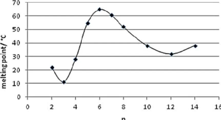
![Figure II-18: Melting point diagram for 1,3-dialkylimidazolium and hexafluorophosphate [PF 6 ] Ionic Liquids as a function of alkyl chain length showing the melting transitions from crystalline (closed square) and glassy (open square) materials](https://thumb-eu.123doks.com/thumbv2/1library_info/3738195.1509145/35.892.265.630.811.1067/melting-dialkylimidazolium-hexafluorophosphate-liquids-function-transitions-crystalline-materials.webp)
+7
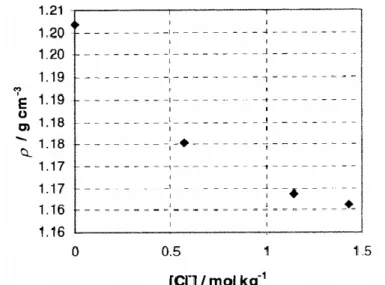
![Figure II-20: Density of different 1-alkyl-3-methylimidazole tetrafluoroborate [C n mim][BF 4 ] Ionic Liquids as a function of temperature 89–91](https://thumb-eu.123doks.com/thumbv2/1library_info/3738195.1509145/37.892.248.653.431.669/figure-density-different-methylimidazole-tetrafluoroborate-liquids-function-temperature.webp)
![Figure II-23: Viscosities of different [C n mim][BF 4 ] Ionic Liquids as a function of the temperature 96,97](https://thumb-eu.123doks.com/thumbv2/1library_info/3738195.1509145/39.892.167.730.583.862/figure-ii-viscosities-different-ionic-liquids-function-temperature.webp)
ÄHNLICHE DOKUMENTE
13 C NMR spectra of a non-catalytically generated cellulose propionate (DS = 3 and 1.4) (top and center) and cellulose propionate (DS = 1-2) from catalytic
9 Screening of ethylene alkoxycarbonylation with n propanol by Pd(OAc) 2 / PPh 3 /methane sulfonic acid at 90 1 C in 1 n butyl 3 methyl imidazolium (bmim) ionic liquids revealed that
From the measured values of the losses ε″ during the thermal decomposition of supported [BMIM][DMP] (Figure 1), the apparent pore fi lling degree α app,RF can be calculated using eq
Metal nanoparticles can be synthesized in ionic liquids [79] through chemical reduction [80 – 85] or decomposition [86 – 89], by means of photochem- ical reduction [90, 91]
[TaCl 6 ] − -containing com- pounds with large organic cations having low melting temperatures might be exhibiting potential application as electrolytes for the
Since the imidazolium cation is (a) an established part of many common ionic liquids and (b) already well- known for its antibiotic activity (cf. introduction) we decided to
While the yields of the formed cyclopropanes are much lower compared to the reactions performed in dichloromethane, the diastereomeric ratio is not significantlyaffected bythe change
Two ruthenium- or rhodium-catalyzed carbenoid reactions – the intermolecular cyclopropanation of styrene with alkyl diazoacetates and the intramolec- ular β -lactam formation
