Research Collection
Conference Paper
Using Sedimentary Basin Geothermal Resources to Provide Long-Duration Energy Storage
Author(s):
Ogland-Hand, Jonathan D.; Bielicki, Jeffrey; Adams, Benjamin; Buscheck, Thomas A.; Saar, Martin O.
Publication Date:
2021-04
Permanent Link:
https://doi.org/10.3929/ethz-b-000467595
Rights / License:
In Copyright - Non-Commercial Use Permitted
This page was generated automatically upon download from the ETH Zurich Research Collection. For more information please consult the Terms of use.
ETH Library
Reykjavik, Iceland, April 26 – May 2, 2020
Using Sedimentary Basin Geothermal Resources to Provide Long-Duration Energy Storage
Jonathan D. Ogland-Hand1,2, Jeffrey M. Bielicki1,3,4, Benjamin M. Adams2, Thomas A. Buscheck5, Martin O. Saar2,6
1Environmental Science Graduate Program, The Ohio State University, USA; 2Geothermal Energy and Geofluids Group, ETH- Zurich, Switzerland; 3Department of Civil, Environmental, and Geodetic Engineering, The Ohio State University, USA; 4The John
Glenn College of Public Affairs, The Ohio State University, USA; 5Atmospheric, Earth, and Energy Division, Physical Life Sciences Directorate, Lawrence Livermore National Laboratory, USA; 6Department of Earth and Environmental Sciences,
University of Minnesota, USA
J.Ogland-Hand: johand@ethz.ch; J.Bielicki: bielicki.2@osu.edu; B.Adams: bejamin.adams@ethz.ch; T.Buscheck:
buscheck1@llnl.gov; M.Saar: saarm@ethz.ch
Keywords: Sedimentary Basin Geothermal, CCS, CCUS, Energy storage, Long-duration energy storage
ABSTRACT
Our prior work developed CO2-Bulk Energy Storage (CO2-BES), which uses geothermal power plants and sedimentary basin geothermal resources to time-shift electricity production. In this study, we investigate the maximum duration over which CO2-BES can time-shift electricity generation because there is increasing evidence that, in addition to shorter-duration energy storage approaches, like batteries, energy storage approaches capable of time-shifting electricity generation over long-durations (>10 hours) or even over seasons will be needed in future decarbonized electricity systems. We use an integrated model that we developed and characterized with specific facility-level assumptions to simulate CO2-BES operation and find that a CO2-BES facility operating under these specific assumptions can time shift electricity over durations of at least one week and likely multiple weeks. Time-shifting electricity generation over longer durations (e.g., one month) depletes subsurface overpressure enough that brine flashes in the production well, but durations longer than a couple weeks are likely possible with different facility-level assumptions. Towards this possibility, we conclude with a few ideas for future work that could enable seasonal energy storage with CO2-BES. Overall, this study suggests that CO2-BES specifically, and sedimentary basin geothermal resources generally, can provide long-duration energy storage and show promise for providing seasonal energy storage.
1. INTRODUCTION
Sedimentary basins geothermal resources are naturally porous and permeable subsurface formations that are ubiquitous but have not conventionally been used for geothermal power production due in part to their colder temperatures when compared to conventional geothermal resources. Despite this disadvantage, prior work suggests that these resources may be used for electricity generation if geologically stored carbon dioxide (CO2) is used as the subsurface working fluid because CO2 is a more efficient heat extraction fluid than brine (Randolph and Saar, 2011; Adams et al., 2015). Even more recently, sedimentary basin geothermal resources and geologically stored CO2 have been investigated to provide energy storage services. For example, CO2-Bulk energy storage (CO2- BES) is an emerging approach that uses geothermal power cycles and a sedimentary basin geothermal resource to time-shift electricity production: electricity is consumed (stored) by pumping brine and CO2 into the sedimentary basin geothermal resource, where energy is stored in the form of pressure, and later, electricity is generated by producing geothermally-heated CO2 and brine to the surface and generating electricity with the geothermal power plants (Buscheck et al., 2016).
Energy storage technologies (e.g., batteries) can provide value to electricity systems in many different applications, for example by deferring investments in generation or transmission infrastructure, by providing ancillary services, enabling energy arbitrage, or by time-shifting electricity generated by variable renewable energy technologies (i.e., wind turbines, solar photovoltaics) to when it is demanded (de Sisternes, Jenkins and Botterud, 2016; Staffell and Rustomji, 2016; Zafirakis et al., 2016; Ogland-Hand et al., 2019;
Mallapragada, Sepulveda and Jenkins, 2020). In addition to daily, hourly, and sub-hourly needs for energy storage, there is an increasing understanding that that energy storage approaches that time-shift electricity generation over long-durations may also be valuable in decarbonized electricity systems (Becker et al., 2014; Mileva et al., 2016; Shaner et al., 2018; Dowling et al., 2020;
Guerra et al., 2020). For example, in addition to time-shifting electricity generation from afternoon to evening, long-duration energy storage (LDS) technologies may also be needed to time-shift electricity that is generated from wind turbines in the winter to the summer when there is greater demand for electricity but less wind energy available.
Despite this potential need for LDS, there are currently limited options for energy storage technologies that can time-shift electricity generation over long-durations (10 hours or greater). For example, the potential for pumped hydro energy storage (PHES), which comprises almost all of installed energy storage capacity worldwide, is limited to the locations that are favorable to PHES. Also, the potential of PHES for LDS over seasonal timescales may be limited by the prohibitively large water storage reservoirs that are necessary to time-shift electricity over months. Similarly, the duration of the charge and discharge cycles of approaches like flow batteries are also physically limited by the limited size of the cathode and anode holding tanks relative to those that are necessary. In contrast, sedimentary basins are massive and relatively ubiquitous (e.g., underlying approximately half of North America (Einsele, 2000; Allen and Allen, 2013)), and thus have both a) ample geospatial availability and b) the physical pore space necessary to hold the large volumes of fluid that are necessary for LDS, even over seasons. As a result, sedimentary basin geothermal resources and approaches like CO2-BES may be uniquely positioned to play an important role in advancing and realizing LDS.
In this study, we investigate the maximum duration over which CO2-BES can time-shift electricity generation. Our prior work suggests that the charge-discharge cycle duration influences the ability of CO2-BES to time-shift electricity by affecting reservoir overpressure, but those findings assume shorter-duration charge-discharge cycles, thus the ability of CO2-BES to provide LDS is unknown (Ogland-Hand et al., 2018). In Section 2 we provide details of our methodology, which included simulating CO2-BES operation in a realistic sedimentary basin case-study in Wyoming, USA. In Section 3 we provide the results from these simulations
Ogland-Hand et al.
2
and in Section 4 we discuss our conclusions and present options for relaxing some of our assumptions, which could be an avenue for future work.
2. METHODS
2.1 Simulating a CO2-BES Facility Providing Long-Duration Energy Storage
We use an integrated model of a CO2-BES facility that we developed in our prior work to simulate CO2-BES operation for fourteen years over five durations of energy storage (Ogland-Hand et al. 2021). The lengths of each cycle that we investigated in this study are: 2 x 12 hours, 2 x 24 hours, 2 x 3 days, 2 x 1 week, and 2 x 1 month. For example, in the cycle with 2 x 3 days duration, the facility continuously alternates between storing energy (injecting CO2 and brine) for three days and dispatching electricity (producing CO2 and brine) for three days over fourteen years (i.e., a single complete cycle lasts 2 x 3 = 6 days).
The integrated model of the CO2-BES facility consists of the Non-isothermal Unsaturated Flow and Transport (NUFT) simulator (Hao, Sun and Nitao, 2012), coupled to a well model, an indirect brine power cycle model, and a direct CO2 power cycle model that we implemented in MATLAB (Ogland-Hand et al. 2021). The NUFT simulator generates results at smaller timesteps than are practical to model with the power cycle models and well model. As a result, we sampled the data from the NUFT output every two years of simulated time, by selecting representative data points from the middle of a charge or discharge duration within each year.
For example, in the 1-month storage and discharge cycle scenario, we used data from month 24.5 to represent dispatching electricity at two years and data from month 25.5 to represent storing energy at two years (Figure 1). This sampling procedure provided representative “snapshots” of the power output capacity and power storage capacity over a multi-year period that could be compared across all of the scenarios that we simulated.
Figure 1: Example of how the data points (blue) were sampled from the data that was generated with NUFT (orange). This example contains results for the 2 x 1 month duration scenario.
2.1.1 Case Study, CO2-BES Facility Design, and CO2-BES Operational Assumptions
We use the same facility-level design and operation assumptions as in our prior work (Ogland-Hand et al. 2021):
1. A generic well-pattern design of the CO2-BES facility that has concentric rings of CO2 production wells (0.5 km radius), CO2 injection wells (2.0 km radius), brine injection wells (2.5 km radius), and brine production wells (4.0 km radius).
2. New CO2 is constantly injected at a rate of 120 kg/s and a portion of the produced brine is not re-injected to limit the maximum downhole injection pressure to 10 MPa above hydrostatic (i.e, the “overpressure” is 10 MPa).
3. The total brine-production flowrate is set to 5,000 kg/s in the priming period and operational period while the total CO2- production flowrate is set to 2,000 kg/s in the priming period and 1,000 kg/s in the operational period.
4. Both the indirect brine power cycle and the indirect CO2 power cycle operate in unison.
5. The CO2-BES facility operates using the Minnelusa Aquifer in the Powder River Basin (Figure 2), which has homogenous properties of 2.7 km deep, 120 m thick, vertical and horizontal permeability and porosity of 10-13 m2 and 16% respectively, and a geothermal temperature gradient of 42 oC/km.
Figure 2: Minnelusa Aquifer within the Powder River Basin in Wyoming, USA.
3. RESULTS
For all but one of the durations that we investigated, the capacities of the CO2-BES facility in the Minnelusa Aquifer are up to ~130 MWe for dispatch and ~55 MWe for storage (Table 1). In other words, the round-trip efficiency of a CO2-BES facility operating with our facility-level assumption (Section 2.1.1) is greater than 100%, as in our prior work (Ogland-Hand et al. 2021). In these cycles, the dispatch capacity is greater than the storage capacity because the constant geothermal heat flux adds energy to the injected CO2
and brine while they are in the reservoir. The storage capacity of the system decreases slowly with time because the geothermal heat is depleted at a faster rate than it can be recharged by the geothermal heat flux, but the capacities were quite similar across the storage cycle durations.
Table 1: Snapshots of Dispatch Capacity and Storage Capacity for the CO2-BES Design.
Storage Cycle Duration
2 x 12 Hours 2 x 24 Hours 2 x 3 Days 2 x 1 Week 2 x 1 Month
Year Dispatch Capacity [MWe]
2 130.40 130.37 130.26 129.92 N/A
4 129.65 129.63 129.51 129.30 N/A
6 129.03 128.97 128.84 128.76 N/A
8 128.57 128.50 128.55 128.50 N/A
10 128.08 128.05 128.23 128.11 N/A
12 127.35 127.32 127.83 127.18 N/A
14 125.91 125.81 125.77 125.96 N/A
Year Storage Capacity [MWe]
2 -52.04 -52.04 -52.05 -52.02 N/A
4 -54.20 -54.24 -52.05 -55.56 N/A
Ogland-Hand et al.
4
6 -56.51 -56.84 -56.50 -53.01 N/A
8 -57.92 -58.37 -56.66 -52.57 N/A
10 -59.23 -59.45 -53.76 -53.16 N/A
12 -57.59 -57.70 -53.85 -52.63 N/A
14 -56.74 -58.66 -54.53 -52.38 N/A
These dispatch and storage capacities are the sum of the dispatch and storage capacities of the indirect brine and direct CO2 power cycles. In each storage-discharge duration scenario, the dispatch capacity due to the CO2 cycle was approximately 8 MWe and injecting new CO2 required approximately 0.8 MWe (Table 2). The remaining dispatch capacity and storage capacity of the facility was provided by the indirect brine cycle and injecting brine from the holding pond.
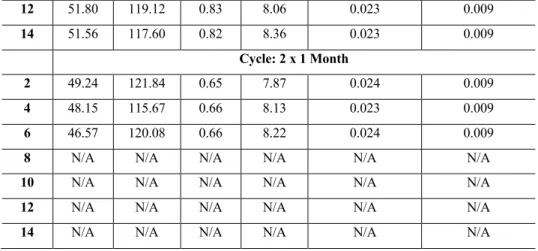
Table 2: Power Cycle Output Results for Each Cycle Simulated.
Year Brine Cycle Storage [MWe]
Brine Cycle Dispatch
[MWe]
CO2
Cycle Storage
[MWe]
CO2
Cycle Dispatch
[MWe]
Brine Cycle Output/Flowrate
Ratio [MWe/kg/s]
CO2 Cycle Output/Flowrate
Ratio [MWe/kg/s]
Cycle: 2 x 12 Hours
2 51.32 122.23 0.72 8.17 0.024 0.009
4 53.39 121.73 0.81 7.91 0.024 0.009
6 55.65 121.29 0.86 7.74 0.024 0.009
8 57.02 120.80 0.90 7.76 0.024 0.009
10 58.30 120.35 0.93 7.74 0.024 0.008
12 56.66 119.33 0.93 8.02 0.024 0.009
14 55.80 117.72 0.94 8.19 0.023 0.009
Cycle: 2 x 24 Hours
2 51.32 122.23 0.72 8.13 0.024 0.009
4 53.45 121.73 0.80 7.90 0.024 0.009
6 55.99 121.29 0.86 7.68 0.024 0.009
8 57.48 120.80 0.90 7.69 0.024 0.008
10 58.52 120.34 0.93 7.71 0.024 0.008
12 56.77 119.33 0.92 7.99 0.024 0.009
14 57.71 117.74 0.94 8.07 0.023 0.009
Cycle: 2 x 3 Days
2 51.34 122.28 0.71 7.97 0.024 0.009
4 51.25 121.77 0.80 7.74 0.024 0.009
6 55.65 121.29 0.86 7.54 0.024 0.008
8 55.80 120.83 0.86 7.73 0.024 0.009
10 52.90 120.36 0.86 7.88 0.024 0.009
12 52.99 119.37 0.86 8.47 0.024 0.009
14 53.66 117.55 0.87 8.22 0.023 0.009
Cycle: 2 x 1 Week
2 51.32 121.85 0.70 8.07 0.024 0.009
4 54.77 121.77 0.79 7.53 0.024 0.008
6 52.22 121.04 0.79 7.72 0.024 0.009
8 51.78 120.53 0.79 7.97 0.024 0.009
10 52.35 120.09 0.81 8.02 0.024 0.009
12 51.80 119.12 0.83 8.06 0.023 0.009
14 51.56 117.60 0.82 8.36 0.023 0.009
Cycle: 2 x 1 Month
2 49.24 121.84 0.65 7.87 0.024 0.009
4 48.15 115.67 0.66 8.13 0.023 0.009
6 46.57 120.08 0.66 8.22 0.024 0.009
8 N/A N/A N/A N/A N/A N/A
10 N/A N/A N/A N/A N/A N/A
12 N/A N/A N/A N/A N/A N/A
14 N/A N/A N/A N/A N/A N/A
Although CO2 is more efficient at extracting geothermal heat than brine, the CO2 cycle can generate less electricity than the brine cycle, largely because the brine flowrate is larger than the CO2 flowrate. As seen in Table 2, this disadvantage in dispatch capacity relative to brine persists even when the power output is normalized by the fluid flowrate, which occurs in part because the dispatch capacity with CO2 is reduced by the additional power requirements to compress and inject the CO2 into the subsurface.
In Table 1, the cycle with 1-month durations of storage and discharge does not have a dispatch capacity or a storage capacity because downhole brine production overpressure drops below -1.44 MPa, which causes the brine to flash in the production well (Figure 3).
Over the course of a given cycle, the overpressure decreases when the facility dispatches electricity because a substantial amount of brine is produced from the reservoir, and the overpressure increases when storing energy because this brine is reinjected (Figure 1).
If the duration is too long, the overpressure will: (a) decrease during dispatch to the point where brine could flash in the production well; and (b) increase during storage to the point where a portion of the produced brine must be permanently removed (i.e., not re- injected) to limit the downhole overpressure to 10 MPa. The downhole production well pressure in the 1-month durations begins to decrease at year two, and at year ten in the 1-week durations, because less brine is re-injected than had been produced.
Figure 3: All Downhole Brine Production Well Overpressure Output NUFT Data. The durations that are shorter than 1 week appear to be split into two sets of data only because the time step taken in the NUFT model was short.
Before brine is removed from the system, the injection well overpressure increases with time across all scenarios because new CO2
is continuously injected into the subsurface. Figure 3 shows that there are data points at the beginning of the 1-week duration in which the overpressure is low enough that the produced brine would flash. As a result, it is likely that a CO2-BES facility designed and operated using the facility-level assumptions we followed for this study (Section 2.1.1) would not operate with 1-week storage and dispatch durations at the beginning of operation. Instead, a shorter cycle would be used until the overpressure increased such that 1- week durations were feasible. Further, there is a ~1 to ~1.5 MPa “buffer” between the overpressure at the end of the dispatch periods
Ogland-Hand et al.
6
in the 1-week cycle and the overpressure that causes flashing (Figure 3). As a result, it is likely that CO2-BES facilities could be used for durations that are longer than 1-week. For example, assuming a linear interpolation between the results for the 1-week durations and the 1-month durations in Figure 3, it is possible that durations of ~two weeks could be feasible without the brine flashing, under the facility-level assumptions we used in this study.
4. DISCUSSION AND CONCLUSIONS
CO2-BES is an emerging approach to energy storage that uses geologically stored CO2 and sedimentary basin geothermal resources to time-shift electricity production. In this study, we performed an initial investigation into the ability of a CO2-BES facility to provide long-duration energy storage (LDS) by using an integrated model that we previously built and characterized to simulate CO2-BES operation across five long-duration charge-discharge scenarios: 2 x 12 hours, 2 x 24 hours, 2 x 3 days, 2 x 1 week, and 2 x 1 month.
We find that:
1. Sedimentary basin geothermal resources and geologically stored CO2 can be used for long-duration energy storage. The CO2-BES facility that we investigated using our facility-level assumptions (Section 2.1.1) successfully time-shifted electricity generation over durations up to a single week but our assumptions must be changed to enable time-shifting over durations of a month. We did not simulate durations between one week and one month, but our results suggest that even under our facility-level assumptions, durations on the order of up to a couple weeks are likely possible. Regardless, our findings clearly demonstrate that CO2-BES facilities can easily meet, and well exceed, the 10-hour duration threshold to qualify as long-duration energy storage. As a result, future researchers should further consider CO2-BES facilities specifically, and sedimentary basin geothermal resources broadly, for providing this service.
2. Assuming the maximum charge-discharge duration length is not exceeded, the power storage and power output capacities are not a function of the charge-discharge cycle length when CO2-BES is operating over long-durations. Our prior work suggested that as long as the charge and discharge cycles were equal, CO2-BES operators could base the duration of storage decisions off financial incentives instead of process-level factors like pressure or heat depletion (Ogland-Hand et al., 2018).
Our findings in this study suggest that this broad conclusion does not hold across all facility-level assumptions for very- long (i.e., seasonal) durations because there may be a maximum charge-discharge duration over which pressure depletion can halt operation, even under equal duration charge-discharge cycles. But with the exception of our one-month scenario in this study, the charging and discharging capacities of CO2-BES were consistent across the energy storage durations, with at most a 0.4% difference in dispatch capacities and a 10% difference in storage capacities. In other words, as long as CO2- BES operators do not exceed the maximum charge-discharge duration length, if one exists, they should not be concerned that providing long-duration energy storage will substantially change the performance of their facility compared to providing time-shifting services over shorter durations.
3. The round-trip efficiency of CO2-BES was largely unaffected by the charge-discharge cycle duration. In our results, the CO2-BES facility could dispatch about 130 MWe and store about 55 MWe across charge-discharge durations. Our prior work documented this approximately 230% round-trip efficiency (Ogland-Hand et al. 2021) and this study suggests that the round-trip efficiency is not a function of the duration of energy storage. This further distinguishes CO2-BES from other potential approaches to LDS that have round-trip efficiencies ranging below 50% and up to around 80% (Albertus, Manser and Litzelman, 2020).
Overall, our findings suggest that CO2-BES can provide long-duration energy storage and has promise for seasonal energy storage.
In addition, our results also do not disprove our prior understanding that the duration of energy storage with CO2-BES is largely an operational decision (Ogland-Hand et al., 2018). In other words, CO2-BES storage operators could provide short or long duration storage services with the same facility. Put another way, the energy storage capital cost of the CO2-BES facility is $0/MWh. This unique characteristic could be particularly important for future grid-integration research because the value of energy storage in electricity systems is sensitive to the energy capital cost (Safaei and Keith, 2015; Guerra et al., 2020).
In addition to grid integration studies, future work could also consider changing one or more of our facility-level assumptions (Section 2.1.1), which will likely enable CO2-BES facilities to provide energy storage over even longer durations (e.g., seasonal time-shifting).
For example, it may be possible to increase the durations of energy storage and energy dispatch beyond a couple weeks by changing the spacing between the concentric rings of wells to better optimize the design of CO2-BES facilities for the site-specific sedimentary basin and specific application. Initially operating over a shorter charge-discharge cycle (e.g., 2 x 3 days) to build up overpressure may also enable operation over longer cycle durations (Figure 3). Additionally, reducing the production flowrate could also further increase the viable durations of storage and dispatch with CO2-BES, but the size of the brine holding pond may render the approach infeasible (Table 3). It is thus likely that for future work investigating seasonal energy storage, the surface holding pond would be replaced by secondary sedimentary basins that are located at shallower depths than the main, deep reservoirs (Fleming et al., 2018).
Table 3: Volume of Brine Holding Pond Required for Different Discharge Durations and Production Flowrates [million United States liquid gallons].
Brine Production Flowrate [kg/s]
Discharge Duration 5,000 4,000 3,000 2,000
12 Hours 57.23 45.78 34.34 22.90
24 Hours 114.46 91.57 68.68 45.79
3 Days 343.39 274.71 206.03 137.36
1 Week 801.25 641.00 480.75 320.50 1 Month 3,481.63 2,785.31 2,088.98 1,392.65
5. ACKNOWLEDGEMENTS
We thank the U.S. National Science Foundation, Sustainable Energy Pathways Program (Grant 1230691) as well as the Sustainable and Resilient Economy Program and the Center for Energy Research, Training, and Innovation at The Ohio State University for their support of the Energy Sustainability Research Laboratory (u.osu.edu/bielicki.2) at The Ohio State University. We also thank the Werner Siemens Foundation (Werner Siemens-Stiftung, WWS) and ETH-Zurich for their support of the Geothermal Energy and Geofluids (GEG) group (GEG.ethz.ch) at ETH-Zurich.
REFERENCES
Adams, B. M. et al. (2015) ‘A Comparison of Electric Power Output of CO2 Plume Geothermal (CPG) and Brine Geothermal Systems for Varying Reservoir Conditions’, Applied Energy. Elsevier Ltd, 140, pp. 365–377. doi: 10.1016/j.apenergy.2014.11.043.
Albertus, P., Manser, J. S. and Litzelman, S. (2020) ‘Long-Duration Electricity Storage Applications, Economics, and Technologies’, Joule. Elsevier Inc., 4(1), pp. 21–32. doi: 10.1016/j.joule.2019.11.009.
Allen, P. and Allen, J. (2013) Basin Analysis: Principles and Application to Petroleum Play Assessment. Third. Wiley-Blackwell.
Becker, S. et al. (2014) ‘Features of a Fully Fenewable US Electricity System: Optimized Mixes of Wind and Solar PV and Transmission Grid Extensions’, Energy. Elsevier Ltd, 72, pp. 443–458. doi: 10.1016/j.energy.2014.05.067.
Buscheck, T. A. et al. (2016) ‘Multifluid Geo-Energy Systems: Using Geologic CO2 Storage for Geothermal Energy Production and Grid-Scale Energy Storage in Sedimentary Basins’, Geosphere, 12(3), pp. 678–696. doi: 10.1130/GES01207.1.
Dowling, J. A. et al. (2020) ‘Role of Long-Duration Energy Storage in Variable Renewable Electricity Systems’, Joule. Elsevier Inc., pp. 1–22. doi: 10.1016/j.joule.2020.07.007.
Einsele, G. (2000) Sedimentary Basins: Evolution, Facies, and Sediment Budget. Springer. doi: 10.1007/978-3-662-04029-4.
Fleming, M. R. et al. (2018) High Efficiency and Large-Scale Subsurface Energy Storage with CO2, 43rd Stanford Workshop on Geothermal Reservoir Engineering. Available at: https://pangea.stanford.edu/ERE/pdf/IGAstandard/SGW/2018/Fleming.pdf.
Guerra, O. J. et al. (2020) ‘The Value of Seasonal Energy Storage Technologies for the Integration of Wind and Solar Power’, Energy
& Environmental Science. Royal Society of Chemistry, pp. 1909–1922. doi: 10.1039/d0ee00771d.
Hao, Y., Sun, Y. and Nitao, J. J. (2012) ‘Overview of NUFT: A Versatile Numerical Model for Simulating Flow and Reactive Transport in Porous Media’, in Zhang, F., Yeh, G.-T., and Parker, J. (eds) Groundwater Reactive Transport Models. Bentham Science Publishers, pp. 212–239.
Mallapragada, D. S., Sepulveda, N. A. and Jenkins, J. D. (2020) ‘Long-run System Value of Battery Energy Storage in Future Grids with Increasing Wind and Solar Generation’, Applied Energy. Elsevier, 275(February), p. 115390. doi:
10.1016/j.apenergy.2020.115390.
Mileva, A. et al. (2016) ‘Power System Balancing for Deep Decarbonization of the Electricity Sector’, Applied Energy. Elsevier Ltd, 162, pp. 1001–1009. doi: 10.1016/j.apenergy.2015.10.180.
Ogland-Hand, J. D. et al. (2018) Operational Characteristics of a Geologic CO2 Storage Bulk Energy Storage Technology, Proceedings of the 14th International Conference on Greenhouse Gas Control Technologies, GHGT-14. Available at:
https://papers.ssrn.com/sol3/papers.cfm?abstract_id=3366316.
Ogland-Hand, J. D. et al. (2019) ‘The Value of Bulk Energy Storage for Reducing CO2 Emissions and Water Requirements from Regional Electricity Systems’, Energy Conversion and Management. Elsevier, 181(April 2018), pp. 674–685. doi:
10.1016/j.enconman.2018.12.019.
Ogland-Hand, J. D. et al. (2021) 'The Value of CO2-Bulk Energy Storage with Wind in Transmission-Constrainted Electric Power Systems', Energy Conversion and Management. 228 (15 January 2021), 113548. doi: 10.1016/j.enconman.2020.113548.
Randolph, J. B. and Saar, M. O. (2011) ‘Combining Geothermal Energy Capture With Geologic Carbon Dioxide Sequestration’, Geophysical Research Letters, 38(May), pp. 1–7. doi: 10.1029/2011GL047265.
Safaei, H. and Keith, D. W. (2015) ‘How Much Bulk Energy Storage is Needed to Decarbonize Electricity?’, Energy and Environmental Science. Royal Society of Chemistry, 8(12), pp. 3409–3417. doi: 10.1039/c5ee01452b.
Shaner, M. R. et al. (2018) ‘Geophysical Constraints on the Reliability of Solar and Wind Power in the United States’, Energy and Environmental Science. Royal Society of Chemistry, 11(4), pp. 914–925. doi: 10.1039/c7ee03029k.
de Sisternes, F. J., Jenkins, J. D. and Botterud, A. (2016) ‘The Value of Energy Storage in Decarbonizing the Electricity Sector’, Applied Energy. Elsevier Ltd, 175, pp. 368–379. doi: 10.1016/j.apenergy.2016.05.014.
Staffell, I. and Rustomji, M. (2016) ‘Maximising the Value of Electricity Storage’, Journal of Energy Storage. Elsevier Ltd, 8, pp.
212–225. doi: 10.1016/j.est.2016.08.010.
Zafirakis, D. et al. (2016) ‘The Value of Arbitrage for Energy Storage: Evidence from European Electricity Markets’, Applied Energy.
Elsevier Ltd, 184, pp. 971–986. doi: 10.1016/j.apenergy.2016.05.047.
Ogland-Hand et al.
8


![Table 3: Volume of Brine Holding Pond Required for Different Discharge Durations and Production Flowrates [million United States liquid gallons]](https://thumb-eu.123doks.com/thumbv2/1library_info/4425577.1584445/7.892.246.648.1037.1159/volume-holding-required-different-discharge-durations-production-flowrates.webp)
