second periplasmic loop P2 of MalF in the maltose transporter of Escherichia coli.
Dissertation
zur Erlangung des akademischen Grades
doctor rerum naturalium (Dr. rer. nat.)
im Fach Biophysik eingereicht an der
Mathematisch-Naturwissenschaftlichen Fakultät I der
Humboldt-Universität zu Berlin
von
Tomas Jacso, Diplom-Ing.
Präsident der Humboldt-Universität Prof. Dr. Christoph Markschies
Dekan der Mathematisch-Naturwissenschaftlichen Fakultät I Prof. Dr. Lutz-Helmut Schön
Gutachter: 1. Prof. Bernd Reif
2. Prof. Erwin Schneider 3. Prof. Udo Heinemann Tag der mündlichen Prüfung: 09.07.2010
Zusammenfassung
ABC (ATP-binding-cassette)-Transporter katalysieren den ATP-abhängigen Transport diverser niedermolekularer Substanzen durch die biologische Zellmembran. Ihr Vorkommen erstreckt sich auf alle drei Domänen des Lebens. Der Maltose Transporter von E.coli gehört zu dieser Superfamilie der ABC-Transporter.
Die Kristallstrukturen des Transporters MalFGK2 wurden kürzlich gelöst für dessen inaktiven Zustand als auch für dessen katalytischen Zwischenzustand. Um den Transportmechanismus besser verstehen zu können, müssen die Kristallstrukturen des Transporters und seiner Komponenten unter physiologischen Bedingungen genau geprüft werden, um den daraus katalytischen Mechanismus zu bewerten. Im rahmen der Dissertation konnte mittels Lösungs-NMR kann gezeigt werden, dass die periplasmatische Schleife P2 von MalF eine unabhängige Faltung aufweist und eine wohl definierte Tertiärstruktur einnimmt, die vergleichbar ist mit der im Kristall vorliegenden Konformation. MalF-P2 interagiert unabhängig von der Transmembranregion von MalF und MalG mit dem Maltose-Bindeprotein in An- und Abwesenheit des Substrats mit einem KD im mikromolaren Bereich. NMR Untersuchungen zu den an der Interaktion beteiligten Aminosäuren stehen in Einklang mit den Kristallstrukturdaten. Die Analyse residualer dipolarer Kopplungen (RDC) zeigt, dass die Konformation der zwei individuellen Domänen von MalF-P2 in Abwesenheit von MalE erhalten bleibt und der im Kristall ähnelt. Die Zugabe von MalE induziert eine Änderung der relativen Orientierung der zwei Domänen von MalF-P2 um so dem räumlichen Anspruch des Liganden gerecht zu werden.
Besonders betroffen hiervon ist die Domäne 2 von MalF-P2, deren Konformation abweicht von der in der Kristallstruktur. Die Struktur der Domäne 1 dagegen bleibt konserviert, während sich lediglich ihre relative Orientierung zu Domäne 2 ändert.
MD Simulationen des MalF-P2-MalE-Komplexes deuten auf eine stark dynamische Interaktion von MalF-P2 mit der MalE Bindungsregion hin. NMR CPMG Kinetikstudien weisen auf die Bildung eines ungewöhnlichen Knicks in α-Helix α2 während der Assoziation hin. Diese konformelle Änderung der α-Helix findet auf einer Zeitskala von Millisekunden statt, was im Einklang mit der Austauschrate der Komplexbildung ist.
Summary
ABC (ATP-binding-cassette)-transporters catalyze the ATP-dependent transport of diverse solutes across the cellular membrane. They are present in all three kingdoms of life. The E.coli maltose transporter belongs to the ATP binding cassette (ABC) transporter superfamily. Recently, the crystal structures of the full transporter MalFGK2 in its resting and a catalytic intermediate state was solved. At the present state of research, it is of particular interest to scrutinize the X-ray structures of the transporter and its components under physiological conditions as well as to evaluate their implications for the catalytic mechanism.
In the context of the PhD thesis, it could be shown using solution-state NMR that the periplasmic loop P2 of MalF folds independently in solution and adopts a well- defined tertiary structure, which is similar to the one found in the crystal structure.
MalF-P2 interacts with the maltose binding protein, independent of the transmembrane region of MalF and MalG, with a KD in the μM range, in the presence and absence of substrate. NMR studies showed good agreement of the residues interacting in solution to those identified in the X-ray structure. Analysis of residual dipolar coupling (RDC) experiments shows that the conformation of the two individual domains of MalF-P2 is preserved in the absence of MalE, and resembles the conformation in the X-ray structure. Upon titration of MalE to MalF-P2, the two domains of MalF-P2 change their relative orientation in order to accommodate the ligand. In particular, a conformational change of domain 2 of MalF-P2 is induced, which is distinct to the conformation found in the X-ray structure. Domain 1 retains its structure but changes its relative orientation to domain 2. MD simulations of the MalF-P2 – MalE complex show a highly dynamic interaction of MalF-P2 to the MalE interface. From NMR CPMG kinetic studies, a peculiar kink of α-helix α2 can be seen introduced upon association. The transition time of this conformational change of the α -helix is on the ms timescale, which is matching the exchange rate of the complex formation.
Table of contents
Zusammenfassung... I Summary...II Table of contents ... III Abbreviations ...VII
1. Introduction...1
1.1. Biology...1
1.1.1 Membrane proteins ...1
1.1.2 General overview of ATP-Binding Cassette (ABC) transporters...2
1.1.2.1 Characteristics of ABC-transporters ...2
1.1.2.2 Substrate transport ...6
1.1.3 The maltose uptake system of E.coli...9
1.1.4 The maltose transporter MalFGK2-E. ...11
1.1.4.1 A transport model for maltose ...13
1.1.4.2 ATP-hydrolysis ...14
1.1.4.3 Characteristics of the transmembrane domains ...15
1.1.4.4 The periplasmic region of MalFGK2...16
1.2 Objectives of this research ...18
2 Results ...19
2.1 Expression and purification of MalF-P2 and MalE ...19
2.1.1 Expression and purification of MalF-P2...19
2.1.2 Expression and purification of MalE ...22
2.2 Characterization of the soluble protein MalF-P2 in solution...23
2.2.1 Mass spectrometry (MS)...23
2.2.2 Analytical ultracentrifugation (AUC) ...25
2.2.3 Circular dichroism (CD-) spectroscopy ...26
2.3 Assignments of the soluble protein MalF-P2 by NMR ...27
2.3.1 Backbone assignments MalF-P2...27
2.3.2 Sidechain assignments of MalF-P2...29
2.4 Structural characterization of MalF-P2 in solution by NMR...31
2.5 Interactions of MalF-P2 and MalE in solution ...33
2.5.1 Chemical cross-linking with sulfonate cross-linkers ...33
2.5.2 Isothermal Titration Calorimetry (ITC) ...34
2.5.3 Titration experiments with MalF-P2...36
2.6 Interactions of MalF-P2 and MalE as seen in the crystal structure of
MalFGK2-E...39
2.7 Structural changes of MalF-P2 upon binding of MalE ...42
2.8 Molecular dynamics experiments of the MalF-P2 and MalE interaction ...46
2.9 Relaxation experiments of MalF-P2 in absence and presence of MalE...49
2.9.1 15N T1-experiments and 15N T2-experiments ...49
2.9.2 1H-15N heteronuclear NOE measurements...50
2.9.3 Molecular weight determination from relaxation rates...51
2.9.4 Carr-Purcell Meiboom-Gill (CPMG)...52
3 Discussion...60
3.1 Structure and function of soluble MalF-P2...60
3.1.1 The interaction between MalF-P2 and MalE ...62
3.1.2 Structural changes of MalF-P2 upon binding to MalE ...65
3.1.3 Binding kinetics between MalF-P2 and MalE ...68
3.2 General discussion ...69
4. Materials and Methods...71
4.1 Chemicals and supplementary equipment...71
4.2 Bacterial strains and plasmids...71
4.3 Media ...71
4.4 Cell growth and storage ...71
4.5 Molecular Biology ...72
4.5.1 Plasmid preparation and amplification ...72
4.5.2 DNA electrophoresis...72
4.5.3 Polymerase Chain Reactions (PCR) ...72
4.5.4 Competent cells and transformation ...73
4.6 Analytical procedures ...73
4.6.1 Determination of concentrations...73
4.6.2 Circular dichroism (CD-) spectroscopy ...73
4.6.3 SDS-PAGE...73
4.6.4 Analytical Ultra Centrifugation (AUC) ...74
4.6.5 Mass spectrometry ...74
4.7 Protein expression, purification and modification ...74
4.7.1 Expression and purification of MalF-P2...74
4.7.2 Expression and purification of MalE ...75
4.7.3 Chemical cross-linking with sulfonate cross-linkers ...75
4.8.1 NMR ...76
4.8.1.1 NMR assignments of MalF-P2 ...76
4.8.1.2 Secondary structure of MalF-P2 ...76
4.8.1.3 NMR relaxation experiments with MalF-P2...77
4.8.1.3.1 15N T1-experiments of MalF-P2...77
4.8.1.3.2 15N T2-experiments of MalF-P2...77
4.8.1.3.3 1H-15N Heteronuclear NOE measurements with MalF-P2 ...77
4.8.1.3.4 Carr-Purcell Meiboom-Gill (CPMG)...78
4.8.1.4 Titration experiments with MalF-P2...79
4.8.1.5 Residual dipolar couplings measurements (RDC)...79
4.8.2 Computational methods ...80
4.8.2.1 Molecular dynamics simulation of the MalF-P2 MalE complex...80
4.8.2.2 Crystal structure analysis ...81
4.8.3 Isothermal Titration Calorimetry (ITC) ...81
5. Figures and Tables...82
6. References...85
Appendix...96
A.1 NMR...96
A.1.1 NMR Theory ...97
A.1.2 Chemical shift assignments...104
A.1.2.1 Backbone assignments ...106
A.1.2.2 Sidechain assignments ...110
A.1.3 Secondary structure from chemical shifts...113
A.1.3.1 Direct interpretation of chemical shifts...114
A.1.3.2 Database analysis of chemical shifts...115
A.1.4 Chemical shift mapping ...117
A.2 NMR relaxation...118
A.2.1 T1-relaxation...120
A.2.2 T2-relaxation...123
A.2.3 Heteronuclear NOE...125
A.2.4 The correlation time, c. ...128
A.2.5 Carr-Purcell Meiboom-Gill (CPMG)...131
A.2.6 Relaxation changes and molecular interactions ...132
A.3 Residual dipolar couplings (RDCs) ...133
A.3.1 The dipolar interaction ...134
A.3.2 Inducing alignment ...135
A.3.3 Determination of the alignment tensor...136
A.3.4 Alignment media...138
A.3.5 Domain orientations and protein complex structures...138
A.3.6 RDC NMR experiments...138
A.4 RDCs of MalF-P2 in presence and absence of MalE...140
A.5 References ...151
Acknowledgements...159
Publications...160
Conferences and Workshops...161
Eidesstattliche Erklärung...162
Abbreviations
ABC ATP-binding cassette ADP adenosine diphosphate
ATP adenosine triphosphate
AUC analytical ultra centrifugation
BP binding protein
BSA bovine serum albumine
CD circular dichroism
Cmr chloramphenicol resistance
CO carbonyl carbon
COSY correlation spectroscopy CPMG Carr-Purcell Meibloom-Gill D2O deuterated H2O
ddH2O aqua bidest
E.coli Escherichia coli
EPR electron magnetic resonance FPLC fast protein liquid chromatograph Ig-like immunoglobuline-like
IPAP in-phase anti-phase
IPTG isopropyl-thio-b-D-galactoside ITC isothermal titration calorimetry
HetNOE heteronuclear nuclear Overhauser effect His6-tag six-histidine tag
HMQC heteronuclear multiple quantum correlation HSQC heteronuclear single quantum correlation
kDa kilo Dalton
MalF-P2 periplasmic loop 2 of MalF MalFGK2 the maltose transporter of E.coli
MBP maltose binding protein (MalE) MS mass spectrometry
NBD nucleotide binding domain Ni-NTA nickel nitrilotriacetic acid NMR nuclear magnetic resonance NOE nuclear Overhauser effect
OD optical density
PAGE polyacrylamide-gelelectrophoresis PCR polymerase chain reaction
pdb protein database
RDC residual dipolar coupling rmsd root-mean square-deviation
RT room temperature
SDS sodiumdodecylsulfate
SN signal-to-noise
τc correlation time
TMD transmembrane domain TOCSY total correlation spectroscopy
TROSY transverse relaxation-optimized spectroscopy w/wo with and without
wt wildtype
Standard chemical or physical abbreviations and symbols are not listed. Amino acids are abbreviated by the one- or three- letter code. Nucleotides are abbreviated by the one- letter code.
1. Introduction 1.1. Biology
This first section will provide a brief introduction to structural studies of membrane proteins and a section containing a general overview of the ATP-Binding Cassette (ABC) transporter superfamily. Following, the maltose uptake system of E.coli and the maltose transporter MalFGK2, which was the topic of this PhD thesis, will be described.
1.1.1 Membrane proteins
Membrane proteins are key players in a cell’s interaction with its surrounding. They perform a wide array of functions as receptor proteins, transporter channels, electrical and photo-inducers1-3. Prokaryotic and eukaryotic genome searches show that roughly 30% of all encoded proteins are in fact membrane proteins4,5. Many disorders are directly dependent on mutations of membrane proteins and it is not surprising that over 50% of all administrated drugs target this class of proteins6-9. The pharmaceutical industry thus has a great interest in high-resolution structures that provide important information about function and mechanistics of membrane proteins.
The first structure of a membrane protein, bacteriorhodopsin, was reported in 1975 by Henderson et al.5. The structure was produced by electron diffraction and resulted in a modest 7 Å resolution structure that nevertheless revealed a bundle of assembled - helices. To date the two most common techniques to obtain high-resolution structures are X-ray crystallography and NMR spectroscopy. X-ray crystallography is dependent on single crystals of sufficient size and regularity that are difficult to obtain in a dynamic environment such as lipids or detergent micelles. NMR does not need single crystals but is limited to the size of the system (<50 kDa). Though both these techniques have their limitations, they have made major progress during the last decades that has lead to an explosive increase in high-resolution structures of membrane proteins, visualized in Figure 1.1.1.1.
Despite major advances in both techniques, the number of deposited high-resolution structures of membrane proteins is alarmingly low in comparison to their importance.
As of February 2009, only 1.7% of all deposited structures in the RSCB databank are membrane proteins, based on OPM10,11 and PDBTM10,11 searches. So far 211 structures of unique proteins could be solved using X-ray crystallography and 33 by using NMR12,13. The current advance in membrane protein structure determination is thus largely accomplished by X-ray crystallography. Though X-ray crystallographers have made great improvements in sample preparation membrane protein crystallization is still a tedious task. Moreover, recent reviews show that solution- NMR and also solid state-NMR groups are making remarkable progress in characterization of membrane proteins14-20. By the combined efforts of the two techniques the future of structural characterization of membrane proteins looks very promising and could one day catch up with the efforts of soluble proteins.
Figure 1.1.1.1. Number of membrane protein structures per year21.
Only unique structures are included. Figure from the website maintained by the Stephen White lab.
1.1.2 General overview of ATP-Binding Cassette (ABC) transporters
ABC-transporters belong to a superfamily that exists in all three kingdoms of life from prokaryotes to humans22, 23. The main function of ABC-transporters is to transport a wide range of substrates over lipid membranes, regulating uptake of nutrients and export of toxins, but they are also involved in non-transport processes as translation, elongation, and DNA repair24-27. The ABC-transporter system utilizes the binding and hydrolysis of ATP to translocate the substrates over cellular membranes.
The importance of these translocation processes are easily realized from the metabolic costs, which are estimated to be roughly 10 – 60% of the ATP requirements in bacteria28,29 and humans30, depending on conditions. ABC transporters are known to play a crucial role in the development of multidrug resistance (MDR), a common clinical problem that occurs in patients suffering from infectious diseases and cancer31,32. Prokaryotic and eukaryotic microorganisms involved in multidrug resistance are frequently detected with overexpression of ABC transporters, but inhibition by low-molecular weight compounds of ABC transporters have not yet yielded satisfying results in clinical trials of cancer patients33,34. Other human pathologies caused by polymorphism in the ABC genes are cystic fibrosis, hyperinsulinemia and macular dystrophy31.
1.1.2.1 Characteristics of ABC-transporters
The ABC-transporter system consists of two transmembrane domains (TMDs) of -
with the ligand in the periplasm for delivery to the appropriate ABC-transporter35. The range of substrates is extremely diverse, ranging from small ions to amino acids and peptides36, and the BPs are highly specific to its substrate or in some cases structurally related substrates, such as maltose and maltodextrins37. In gram-positive bacteria, which lack an outer membrane and thus a periplasm, they are either anchored to the outer leaflet as lipoproteins or directly fused to the transmembrane domains of the ABC-transporter25. The BPs not only functions as high-affinity binding proteins but can take on other regulatory tasks as in the maltose system of E.coli where the substrate bound BP MalE interacts with Tar as a chemoreceptor38. Exporters do not require the high-affinity binding proteins, but instead contain large intracellular loops (ICDs) that extend the TM helices roughly 25 Å into the cytoplasm39. The intracellular domains keep the two nucleotide binding domains apart in the resting state allowing the substrate to interact with the intracellular parts of the transmembrane domains. The function of substrate recognition for the export systems is far less understood then for its import system counterpart.
Figure 1.1.2.1.1 The ABC-transporter architecture.
Panel A depicts the ABC importer system with the transmembrane domains (TMDs), the nucleotide binding domains (NBDs) and the substrate binding protein (SBP) for prokaryotic transporters. In gram- negative bacteria the SBP is attached to the outer leaflet of the lipid bilayer as a lipoprotein, depicted as a dashed line in panel A. Panel B depicts the architecture of ABC exporters. Exporters differ from importers in that they have long intracellular loops (ICDs), which extend the TMDs into the cytoplasm.
The sequence and the architecture of the TMDs vary greatly, reflecting the chemical diversity of the translocated subtrates. The number of -helices for ABC-transporter systems varies between 5 and 10 for each TMD40. The -helix bundle creates the translocation pathway through the lipid membrane and upon ATP-hydrolysis the pathway switches between different conformations allowing access to either the extracellular or intracellular compartments of the cell for the substrate.
In contrast to the great variety in the TMDs the NBDs are highly conserved consisting of a RecA-like and a helical domain, with several characteristic motifs in both domains40. These motifs include the Walker “A and B” motifs41, common to many nucleotide binding proteins, and the LSGGQ-, the stacking aromatic-, H- and Q- loops39. These motifs are essential for binding and coordination of ATP for the hydrolysis step where the chemical energy in ATP is transferred into “mechanical”
energy for the transporter42. The coordination of ATP of the different motifs is shown for the MalK dimer of the maltose transporter in Figure 1.1.2.1.2. Further the two NBD nucleotide-binding sites always face each other and the NBDs are always present as dimers in the fully assembled transporter25.
Figure 1.1.2.1.2. Schematic diagram of the interaction between one of the two ATPs bound to the homodimer of MalK in the maltose transporter.
Interactions by the different conserved motifs in the NBD are marked out for their respective subunit, subunit A (RecA-like) and subunit B (helical domain). Black lines represent van der Waals contacts, and blue lines correspond to hydrogen bonds and salt bridges. Figure adapted from Chen et al.42
The interface between the TMDs and the NBDs of the fully assembled transporters is formed by intracellular conserved coupling helices (EAA-loops), which interact with the grooves on the NBDs’ surfaces43. This interaction forms a “ball-and-socket” joint that is similar among all ABC transporters although very low sequence homology is apparent. It is therefore believed to be a common mechanism of coupling motions between the NBDs and TMDs that allow large rigid body movements during structural transitions25,44.
The extracellular loops of the TMDs are also believed to be important for function of ABC-transporters. They can possibly be involved in a wide range of interactions such as substrate recognition, protein complex stabilization and signal transduction from the extracellular parts to the intracellular NBDs. A few examples can be found for the MalFGK2-E transporter. In the crystal structure of a catalytic intermediate of the transporter the periplasmic loops P3 of MalG and P2 of MalF make several important interactions. The loop P3 of MalG is deeply inserted into the substrate-binding pocket of MBP. Oldham et al. propose that the P3 loop “scoops” the substrate out by
domain of MalE in a cap-like manner45. The specifics of this interaction are not yet understood. Biochemical studies show that the periplasmic loops P2 of MalG and P1 of MalG interact with the substrate-binding protein throughout the catalytic cycle and that the P2 loop also could be responsible for communicating substrate availability to the NBDs47-49.
ABC-transporters can be structurally characterized by the arrangement of the TMDs.
The protein fold can be divided into three categories; the type I ABC importer (e.g.
MalFGK245 and MetNI50), the type II ABC importer (e.g. vitamin B12 transporter51) and ABC exporters (e.g. Sav186652 and MsbA53).
Figure 1.1.2.1.3 depicts the crystal structures of ModB2C2-A, BtuCD-F and Sav1866, which represent the three different folds.
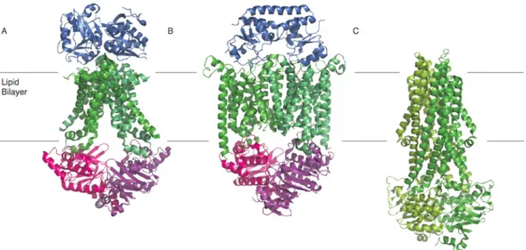
Figure 1.1.2.1.3. Structural characterization of ABC-transporters.
Panels A to C depict crystal structures of ModB2C2-A54, BtuCD-F51 and Sav186652, from left to right.
The three crystal structures refer to the type I ABC importer, the type II ABC importer and the ABC exporter, respectively. Figure generated with PyMol55 and pdb codes: 2ONK, 2QI9 and 2HYD, respectively.
In contrast to the classification of ABC-transporters by structure, Davidson et al.
recently presented a new mode of classification based upon sequence comparison25. Three classes can be distinguished; Class I encompasses transporters with the TMD and NBD domains fused together in a single polypeptide chain, Class II includes non- transport ABC-transporters lacking TMDs, and Class III have separate polypeptide chains for the TMD and NBD domains. A comparison of these two different classifications reveals some interesting features that are relevant to the existence of structurally uncharacterized TMD folds39.
1.1.2.2 Substrate transport
With the available structural and biological data of different ABC systems two different models have been proposed for the translocation mechanism of substrate; the alternating-access model39 for import systems and the ATP-switch model56 for export systems. Schematics of the two different transport models are represented in figures 1.1.2.2.1 and 1.1.2.2.2 respectively.
The alternating-access model is based on the ABC importer systems, which include the high-affinity substrate binding proteins and includes three major steps. In the resting state the transmembrane domains of the importer systems are in an inward- facing conformation with the nucleotide binding domains being held open in an outward-facing conformation. The substrate-loaded binding protein docks into the periplasmic side of the transmembrane domains triggering the ATP binding to the nucleotide binding domains and closing their interface. Upon closure of the nucleotide binding domains the transmembrane domains switches to its outward-facing conformation allowing access to the transport pore for the substrate. ATP is then hydrolyzed opening the dimeric interface. Consequently the transmembrane domains switch back into the inward-facing conformation, releasing the substrate and allowing access to the cytoplasm. After release transport of substrate ADP and Pi is released from the nucleotide binding domains, reverting the transporter back into its resting state39.
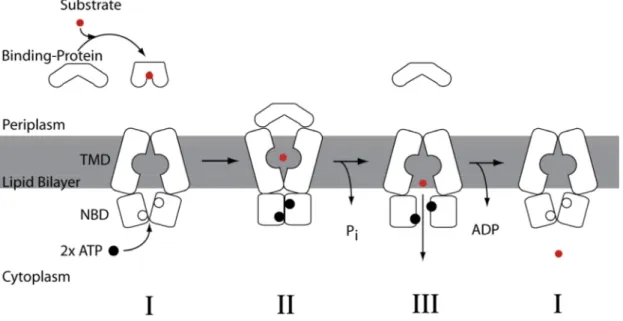
Figure 1.1.2.2.1. The alternating-access model is based on the crystal structures of ModBC-A54, HI1470/157 and MalFGK245.
The model contains three major structural changes before reverting back into its resting state.
transmembrane domains are in an inward-facing conformation in the resting state in consensus with the alternating-access transport model for ABC importer systems. In contrast to the import systems the nucleotide binding domains are relatively far apart to accommodate the amphiphilic and hydrophobic substrates. The intracellular domains of export systems extend the transmembrane domains into the cytoplasm facilitating the space between the nucleotide binding domains contra as seen in the import systems. In MsbA the substrate-binding pocket is large enough to accommodate the relatively large sugar groups of lipopolysaccharides (LPS)53. Binding of the substrate and binding of ATP to the nucleotide binding domains, closes the dimer interface, triggering the transport cycle. Upon closure of the dimeric interface of the nucleotide binding domains the transmembrane domains undergoes conformational changes in consensus with the alternating-access model. The sugar head groups are sequestered within the substrate-binding pocket in the transmembrane domains upon the closure of the nucleotide binding domains. The substrate-pocket of MsbA is lined with charged and polar residues energetically favourable for polar moieties in amphiphilic compounds or sugar groups of lipopolysaccharides (LPS) and highly unfavourable for hydrophobic substrates. It is believed that the unfavourable environment for the hydrophobic parts of LPS or substrates causes it to “flip” into an energetically more favourable position with the hydrophobic moieties positioned in the outer membrane leaflet. Upon the conformational changes of the transmembrane domains the rigid-body shearing during the movement could cause the hydrophobic moieties to be dragged through the lipid bilayer. Hydrolysis of one ATP is believed to widen the periplasmic opening of the transmembrane domains and pushing the substrate towards the outer leaflet of the lipid bilayer. Hydrolysis of the second ATP and release of Pi causes opening of the dimeric interface of the nucleotide binding domains restoring the transporter into its resting state with the transmembrane domains in the inward-facing conformation and the nucleotide binding domains separated53,58.
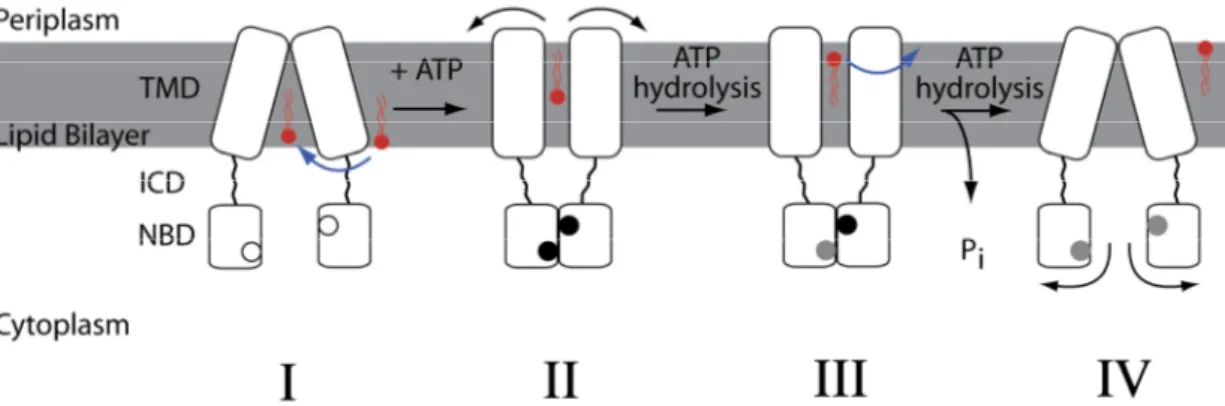
Figure 1.1.2.2.2. The ATP-switch model is based on structural and biochemical studies on MsbA and contains four major structural steps.
Nucleotide-free NBDs are seen as boxes with white-filled circles, ATP-bound NBDs with black-filled circles and ADP-bound NBDs with grey-filled circles.
Complete understanding of how the transport cycle of ABC transporters occur has not yet been elucidated. The key question of how transport of substrates is initialised and if periplasmic or cytosolic parts trigger the catalytic cycle are still one of many questions that needs to be answered. Vast amounts of structural and biochemical data support a model in which ATP binding and hydrolysis is coupled to the conformational changes in the transporter. It is still debated whether substrate binding or nucleotide binding occurs first25,44,59-62 and if the power-stroke is provided by the closure of the NBDs or by the ATP-hydrolysis63,64.
Though ABC-transporters are of great interest for the pharmaceutical industry, they have not yet been extensively investigated by structural biology methods. As of date, 17 X-ray structures exists of nine ABC-transporters of unique protein sequences (Table 1.1.2.2.1), none from human13.
As described above ABC-systems are large multi-protein complexes, and are difficult to access by solution-NMR due to their size. So far, X-ray analysis has been the only method for obtaining structural information. Large uniformly labelled proteins yield spectra of high complexity and thus require tedious analysis, but new NMR based approaches show great promise. To tackle these systems a well suited approach is that of “divide-and-conquer” where the complexity could be greatly reduced by labelling of specific domains and later assembled back for the full system. Intein technology already exists that can provide such labelling schemes65-67, but now needs to be applied for appropriate complex systems. Another approach is to examine smaller parts of the system within the size limits of solution-NMR. To circumvent the size limit of solution-NMR solid-state NMR could be applied to access these systems. Not only is solid-state NMR not limited by size but it can also acquire dynamic features not accessible by EPR or X-ray. Solid-state NMR provides the possibility to use ABC transporters reconstituted into liposomes or even extracted membranes from the bacteria, greatly simplifying purification protocols and allowing structural studies in native environment. Though Solid-State NMR seems like an ideal technique for these systems technical issues still need to be addressed before it can be used on regular basis for membrane protein systems.
Table 1.1.2.2.1. Currently determined ABC-transporter structures as of Dec 2009.
The structures are presented with their pdb code from the RSCB data bank70, experimental method and reference. Data from the White lab homepage13.
System and host Pdb code Method Reference
BtuCD Vitamin B12 Escherichia coli 1L7V X-ray Locher et al. 200251 Sav1866 Staphylococcus aureus 2HYD X-ray Dawson & Locher 200652 ModB2C2-A Archaeoglobus fulgidus 2ONK X-ray Hollenstein et al. 200754 HI1470/1 Haemophilus influenzae 2NQ2 X-ray Pinkett et al. 200757 MsbA-AMPPNP Salmonella typhimurium 3B60 X-ray Ward et al. 200753 P-glycoprotein Mus musculus 3G5U X-ray Aller et al. 200968 MalFGK2-MBP Escherichia coli 2R6G X-ray Oldham et al. 200745
MetNI Escherichia coli 3DHW X-ray Kadaba et al. 200850
1.1.3 The maltose uptake system of E.coli
The rod shaped gram-negative bacteria Escherichia coli is commonly found in the gastrointestinal system of warm-blooded organisms, where it scavenges its nutrients from the hosts metabolic system. One of these nutrients is maltose or maltodextrins and is regulated by the maltose system of the bacteria. The maltose system has been known for over 40 years and involves a myriad of molecules and regulatory phenomena with only a few being mentioned here71. Gram-negative bacteria are characterized by its cell wall. The cell wall contains two membranes, an outermembrane and an inner membrane. The outer membrane is made up of a lipopolysaccharide layer to a peptidoglycan layer, which is often associated with the pathogenic abilities of the bacteria72. The inner membrane, which is entirely made up of peptidoglycan, is much thinner than found in gram-positive bacteria, which only have one membrane layer72. The two layers are separated by a periplasmic space, which can constitute up to 40% of the total cell volume and has a loose network of murein chains and also contains degradative enzymes73.
The uptake of maltodextrins of E.coli requires multiple steps of transport over the two membrane layers before the bacteria can utilize it in its metabolic pathways. Figure 1.1.3.1 provides a coarse schematic of the elaborate transport systems of the scavenged substrates into the cytoplasm from the cells surroundings.
Figure 1.1.3.1. Schematic of the maltose uptake system of E.col.
Maltoporin allows maltose/maltodextrins to diffuse through the outer membrane from the bacteria’s surroundings. The periplasmic substrate-recognition protein MalE binds substrate at high-affinity and functions as the recognition site for the ABC transporter MalFGK2 in the inner membrane. Pdb codes 1MPM, 1OMP and 3FH6 were used for the structures of Maltoporin, MalE and MalFGK2, respectively.
Efficient uptake of maltose/maltodextrins at low concentration in the living environment of the bacteria requires a highly specific diffusion pore into the
This trimeric 18-stranded antiparallel -barrel contains a wide channel in each of the subunits74 and does not only mediate maltodextrins uptake but also other carbohydrates under starvation conditions75,76. Crystal structures of maltoporin complexed with maltose, maltotriose or maltohexaose gives a detailed picture of how the porine functions. The pore’s channel entrance is lined with a series of aromatic residues that are arranged in a helical pathway into the pore. These aromatic residues are spaced 6-7 Å apart and make transient bonds to hydrophobic faces of sugar molecules guiding the substrate through the pore. The aromatic helical path is also called the “greasy slide” and is surrounded by hydrophobic residues and are assumed to convey sugar specificity77,78. The uptake of maltose/maltodextrins from the periplasmic space into the cytoplasm is controlled by the multicomponent and periplasmic binding-protein dependent ABC high-affinity transport system MalFGK2
– E79,80. Substrate recognition by the system is determined primarily by the periplasmic protein MalE that occurs at high concentration, ~1 mM and in a 30 – 50 fold excess over MalFGK281, in the periplasmic space. The MalFGK2 system can only transport linear maltodextrins up to six glucose units, maltohexaose, whereas MalE also binds cyclodextrins and p-nitrophenyl derivates of maltooligosaccharides82,83. This is due to the mode of binding of the substrates to MalE. Substrates that are bound at the reducing end and not within the dextrinyl chain are subjected to transport. For efficient uptake of maltodextrins the periplasm also contains the -amylase MalS, which cleaves maltodextrins but not maltose. Its preferred product released from larger maltodextrins is maltohexaose, the largest maltodextrins subjected to transport by MalFGK284. It thus has the function to degrade larger maltodextrins that entered the periplasm through the maltoporin system to shorter dextrins that can be transported into the cytosol85. The ABC high-affinity transport system MalFGK2, which is responsible for the transport of the substrates of MalE will be described later in more detail. Furthermore, the cytosol contains the three enzymes MalP, MalQ and MalZ, which metabolize incoming maltose and maltodextrins into glucose and glucose-1-phosphate, by combined action, which are used in the glucolysis of the bacteria37.
The major regulatory unit of the maltose uptake system is the cytosolic protein MalT, which acts as a positive regulator. It is activated by an inducer, maltotriose, whose synthesis is directly dependent on the metabolic state of the cell and stimulates transcription by activating RNA polymerase86. Other regulatory systems of the maltose uptake system are the global carbohydrate regulation of the cell, which is effected by the cAMPCAP system37 and the dephosphorylated form of glucose- specific enzyme IIA of the bacterial phosphotransferase system (PTS) that inhibits transport activity by direct inhibition by binding to the MalK dimer of the MalFGK system located in the inner membrane37.
Table 1.1.3.1. Mal genes of the maltose uptake system with their product and function.
Table adapted from Boos and Shuman37.
Gene Gene product and function
malT MalT: transcriptional activator, essential for transcription of all mal genes except the malI/X/Y gene cluster. Binds ATP and maltotriose as inducer.
malE MalE: periplasmic MBP; binds maltose/maltodextrins with micromolar affinity.
malF MalF: integral membrane protein of the transporter system. In association with MalG and MalK, it forms the MalFGK2
translocation complex.
malG MalG: integral membrane protein of the transporter system. In association with MalF and MalK, it forms the MalFGK2
translocation complex.
malK MalK: transport ATPase, responsible for energization of transport. In association MalF and MalG, it forms the MalFGK2
translocation complex. Target of inducer exclusion by unphosphorylated EIIAGLC of the PTS. In the absence of the inducer, it interacts with MalT to cause repression.
lamB Maltoporin: receptor for phage and specific pore for maltodextrins (maltoporin, glycoporin).
malM Periplasmic protein of unknown function partially associated with the outer membrane. Contains an Ala-Pro linker also found in OmpA.
malP Maltodextrin phosphorylase. Substrates are maltopentaose and larger maltooligosaccharides. malP mutants still grow on maltose but accumulate large amount of maltodextrins under conditions.
malQ Amylomaltase. Maltodextrinyltransferase with maltotriose as the smallest substrate. malQ mutants cannot grow on maltose, are sensitive to maltose, and are constitutive for mal gene expression.
malS Periplasmic -amylase, cleaves preferentially hexaose from the nonreducing end of meltotextrins.
malZ Maltodextrin glucosidase and -cyclodextrinase, cleaves glucose sequentially from the reducing end of maltodextrins. Maltotriose is the smallest substrate. It linearizes -cyclodextrins but not - and -cyclodextrin.
1.1.4 The maltose transporter MalFGK2-E.
One of the best characterized ABC systems is that of the MalFGK2-E transport system. A vast amount of biochemical and structural data have been gathered on the system for the last four decades and has given it a position as a model system for ABC transporters. This bacterial ABC-import transporter consists of the substrate- binding protein MalE, the transmembrane domain proteins MalF and MalG and the ATPase homodimer MalK.The transporter has been characterized structurally and two crystal structures exists of the maltose transporter in its resting-state87, in absence of its substrate-binding protein MalE, and in a catalytic-intermediate state with MalE tightly associated to the transmembrane domains MalF and MalG45. In conjunction there are also crystal structures available for the ATP-Binding Cassette Dimer MalK
in three different conformations42. The crystal structures correspond well to the three different catalytic steps in the alternating-access model.
Figure 1.1.4.1. The maltose transporter45,87.
MalFGK2-E in its resting-state87 (left) with the TMDs in an inward-facing conformation and with the NBDs open, and a catalytic-intermediate state45 (right) with the TMDs in an ouward-facing conformation with the SBP tightly associated and the NBDs closed with ATP bound. The maltose substrate is also seen bound in the pore of the transporter, presumably in its binding pocket45.
The crystal structures of MalFGK2-E show that the conformations of the transmembrane domains and nucleotide-binding domains are in agreement with the postulated transport model of ABC-importer systems, which was based on the crystal structures of ModBC-A54 and HI1470/157.
The transport system utilizes the chemical energy stored in ATP to bring about the conformational changes necessary for transport of substrates. The MalK dimer on the cytoplasmic side of the transporter binds ATP and harnesses this energy into
“mechanical” movement of the transmembrane proteins MalF and MalG, alternating them between an inward-facing and an outward-facing conformation. The substrate- binding protein MalE regulates ATP hydrolysis of MalK by interaction with the periplasmic parts of MalF and MalG, triggering the ATP hydrolysis. Studies of the binding protein show that it can interact with the transporter both in its substrate- bound and substrate-free form though both forms have distinctively different conformations88. Though both forms can interact with the transporter catalytic activity studies show that maximal rates of ATP-hydrolysis are detected only in the presence of substrate-bound MalE, 1400 and 5 nmol/min*mg for substrate-bound and
at low amounts of maltose and maltodextrins in the cells surroundings. This to keep the maltose uptake system on “stand-by” until more favourable substrate conditions in the cells living environment is available. As earlier described, MalT is a positive regulator of the transcription of the whole maltose uptake system where it interacts with the C-terminal domain of MalK. MalK can shift between two states, one being associated with MalF and MalG at the inner membrane leaflet and one as being associated to MalT in the cytosol37. In the presence of substrate MalK is associated with MalF and MalG allowing MalT to function as a mal gene activator. In the absence of substrate MalK interacts with MalT and acts as a repressor. A similar mechanism has been seen for the proline utilization system, where PutA, the proline dehydrogenase, functions as a membrane-bound enzyme in the presence of proline and as a cytoplasmic repressor in its absence89.
1.1.4.1 A transport model for maltose
The MalK dimer sites in a semi-closed state upon binding of ATP and not until substrate-bound MalE binds to MalF and MalG will the ATP-bound MalK dimer close its interface. ATP is found in high concentrations in the cytoplasm, roughly 1 mM90, and thus it is thought that the MalK dimer resides predominately in its semi- closed form. The fully closed MalK dimer triggers a conformational change of MalF and MalG from its inward-facing conformation to its outward-facing conformation, allowing MalE to tightly associate to the transporter. The substrate now has access to the membrane pore and can bind into the substrate binding cavity of MalF and MalG.
After ATP-hydrolysis MalF and MalG switches back into its inward-facing conformation releasing the substrate and shuttling it into the cytoplasm. ADP and free Pi is then released and the transporter goes back into its resting-state, ready for another transport cycle. The postulated three-step mechanism is shown in figure 1.1.4.1.1.
Figure 1.1.4.1.1. The alternating-access transport model adapted for MalFGK2-E.
The three step model show the structural changes of the transmembrane proteins MalF and MalG, switching between inward-facing and outward-facing conformations during the catalytic cycle (steps
). The figure shows the MalK dimer interface closing upon binding of ATP and substrate- bound MalE (step ), allowing access of the substrate to the membrane pore, and the opening of the dimer interface upon hydrolysis of ATP (steps ), releasing substrate into the cytoplasm. After
release of ADP and Pi the transporter goes back into its resting-state (. Figure adapted from the alternating-access model based on ModBC-A54 and HI1470/157.
1.1.4.2 ATP-hydrolysis
The most pronounced feature of the ABC-transporter system is its ability to harness the chemical energy in ATP into mechanical movements of the transporters. This feature is directly attributed to the nucleotide binding domains and their conserved motifs. The mechanism of hydrolyzing ATP enables the NBDs to be considered as ATPase enzymes. The nucleotide binding domain MalK in MalFGK2-E contain an unique characteristic in the regulatory C-terminal domains towards most other NBDs.
This feature stabilizes the dimer interface and Chen et al.42 were successful in utilizing this to crystallize the dimer in three different conformational steps, open, semi-open and closed42. The crystal structures show the closure and opening of the dimer as a “tweezers-like” motion, with the C-terminal domain as the handle and the N-terminal domains as the “tips” of the tweezers42. The switches between the different conformational steps are not a single action motion but instead as a multiple action motion where the closure of the “tweezer tips” is accompanied by an intra- monomer rotation of the helical domains towards the RecA-like domains, enabling the LSGGQ-motif to contact ATP across the dimer interface and fully closing it.
Furthermore, a second rotation adjusts the entire NBDs orientation to the regulatory domains. Figure 1.1.4.2.1 show the orientational differences of the NBDs in the closed, semi-open and open-state.
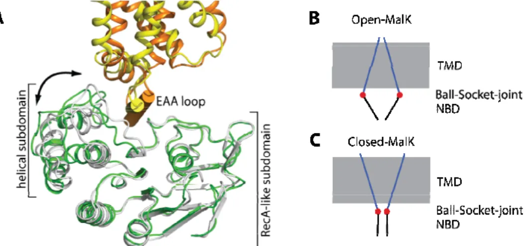
Figure 1.1.4.2.1. Closed, semi-open, and open structures of MalK homodimer with superimposed regulatory domains42.
The distances between two H89 residues in a homodimer are indicated. A show the superimposed closed form with ATP bound, yellow, and the semi-open form without ATP bound, blue. The excellent overlap of the regulatory domains is evident by the green color resulting from the combination of blue
The conformational changes of the NBDs are transferred to the TMDs through the coupling-helix motif in the transdomain proteins. These helices create the interface between the MalK dimer and the transdomain MalF/G proteins. The coupling helices are situated in the last cytoplasmic loops of the transmembrane proteins MalF and MalG52. They are architecturally conserved through the ABC-transporters with a consensus sequence of EAA-X3-G-X9-I-X-LP, and are also known as the “EAA”- or L-loops91. In the crystal structure of MalFGK2 these two short helices docks into a surface cleft in each MalK subunit and rotates about 300 during the inward- and outward-facing conformations87. The MalK cleft consists of two helices from the helical subdomain, the helix following the Walker A motif and residues in the Q- loop42. The closure of the MalK dimer triggers the reorientation of the coupling helices to their transmembrane helices and rearranging the TMDs from the inward- and outward-facing conformations. The MalK dimer thus produces the “power- stroke” to enable the mechanical movements of the transporter. The docked coupling- helix in the MalK subunit is seen in Figure 1.1.4.2.2 as well as a schematic of the
“power-stroke” through the NBDs to the TMDs via the ball and socket joint.
Figure 1.1.4.2.2. The “ball and socket joint” between the transmembrane proteins MalF and MalG and the nucleotide binding proteins MalK287.
A The open- and closed-state structures are superpositioned based on the the RecA-like subdomains of MalK. The NBDs of MalK from the inward- and outward-facing structures are shown in green and gray, respectively. MalG is rendered in yellow (resting state) and orange (transition state). The coupling helix is labelled as “EAA loop”. B-C Show the general principle of the “ball and socket joint”
(red filled circle) of the coupling helices between the open- (B) and closed-state (C) of the MalK dimer (black lines) and MalF and MalG (blue lines). Conformational changes upon closure of MalK are exaggerated in the figure. Figure adapted from Khare et al.87
1.1.4.3 Characteristics of the transmembrane domains
With the availability of the crystal structures of the maltose transporter, in its resting- and an intermediate-state87,45, the rearrangement of the transmembrane proteins MalG and MalF can be evaluated in detail. Davidson et al. divides each TM subunit into two regions; a core region consisting of the central four helices (TM helices 2-5 in MalG and 4-7 in MalF) and a peripheral region containing helices surrounding the core87. The subunits are arranged in an intertwined configuration with a pseudo-2-fold
symmetry, where the peripheral helices of each subunit pack against the other subunits core helices. During the conformational changes the core regions maintain their structures and are seen moving as rigid bodies. The two rigid bodies change their rotation to another by 220 with an almost orthogonal rotation axis 450 to the membrane plane. The rotation is also accompanied by an 4Å translation along the rotational axes, when using the MalK regulatory domains as a frame of reference45. The crystal structures also show a gating mechanism for the substrate to its binding cavity in the pore45. Four loops located at the bend of a kinked TM helix creates a hydrophobic gate for the substrate in the inward-facing conformation87. A similar gating architecture was also observed in the ModB2C2A transporter54. The core regions and the gating loops in the inward- and outward–facing conformations are shown in Figure 1.1.4.3.1.
Figure 1.1.4.3.1. Conformational changes in the transmembrane subunits in the catalytic cycle87. A, shows the cartoon of the translocation pathway in the resting state (left) and the transition states (right). A, red star indicates the location of maltose in the outward-facing conformation. Gating loops are shown in red. The two coupling helices, “EAA”-loops, of MalF and MalG, are labelled “EAA” and
“EAS” respectively, based on their sequence. B, stereoview of the TM cores: the inward- and outward- facing structures are superimposed based on the MalK regulatory domains. The gray lines indicate the two rotation axes relative to the regulatory domains. Color codes are as follows: MalG resting state, yellow; transition state, orange; MalF resting state, blue; transition state, cyan. Figure adapted from Khare et al.87
1.1.4.4 The periplasmic region of MalFGK2
Through the crystal structures of the maltose transporter much can be learned about the transport mechanism. Some of the information is however lost, this entails the dynamics and the mobile regions of the transporter. These mobile regions encompass the periplasmic loops of MalF and MalG, which either show very poor or no electron
according to their termini25. A hinge region between the two lobes allows the two domains to open and close. Upon binding of substrate, which is located in the interior between the two domains, MalE closes making the binding cleft inaccessible to the aqueous surroundings92.
Figure 1.1.4.4.1. Architecture of the transmembrane subdomains MalF and MalG according to the crystal structure45.
Schematic representation of the secondary structure elements of MalF (blue) and MalG (yellow). The gating loops are located in the kink of helix 5 of respective membrane spanning protein. The first and last residues of each TM helix, predicted to be buried by the lipid acyl chains, are marked out in the figure. Figure adapted from Oldham et al.45
Recent studies show that the periplasmic loops P1 and P3 of MalG and P2 of MalF are important for substrate recognition and stabilization of the transporter complex and also possibly having other functionalities47-49. They were analyzed by tryptic digestions experiments, fluorescence measurements and site-directed cross-linking and was observed undergoing conformational changes and/or large rigid body motions during the catalytic cycle47-49. The P1- and P2-loop of MalG and MalF, respectively, binds to one of the two lobes of MalE and their interaction are thought to stabilize the associated complex during the transport cycle47-49. As earlier described in section 1.1.2, the P3 loop of MalG is deeply inserted into biding pocket of MalE and Davidson et al. postulates that it “scoops” the substrate out from the pocket into the transmembrane pore45. The 20 kDa large P2 loop of MalF is an exception among ABC-transporters and is only found in gram-negative enterobacterial bacteria. It is seen binding the N-lobe of MalE in a cap-like manner with an Ig-like structure in the catalytic intermediate state crystal structure of MalFGK245. In conjunction the P1 loop of MalG is seen binding complementary to the C-lobe of MalE47,48. No data is currently available on the structure or position of the P2-loop in the resting-state or its function during the catalytic cycle. The basis of this work was to characterize the P2- loop’s interactions to MalE during the catalytic cycle and to further understand its
Figure 1.1.4.4.1 show the topology and the location of the periplasmic-, “EAA-”, and the gating-loops.
1.2 Objectives of this research
ATP-binding cassette (ABC) transporters are ubiquitous membrane protein complexes that use the energy generated from ATP hydrolysis to transport solutes across the membrane. In bacteria, the majority of ABC transporters are importers that consist of a substrate-binding protein, two integral membrane components and two membrane- associated ATP-binding cassettes. One classical representative is the maltose transporter of Eschericha coli / Salmonella composed of the periplasmic maltose binding protein (MBP) MalE, the two integral cytoplasmic membrane proteins MalF and MalG and two copies of the ATPase subunit MalK. In bacteria and archaea, binding proteins are the main determinants of substrate specificity. The determination of the crystal structure of the reconstituted maltose transport MalFGK2 in complex with MalE has recently drawn a lot of attention to this system. There, the large periplasmic loop P2 of MalF (MalF-P2) is in contact with MalE from which maltose has already been released. In fact, MalF-P2 seems to act as a receptor, which recruits MalE and thus maltose, to the core of the membrane protein. An alternative docking site involves the periplasmic loop P3 of MalG, which interacts with the maltose binding site of MalE in the X-ray structure. The question how much MalF-P2 contributes to substrate recognition is still unresolved. Earlier genetic and biochemical investigations show that both MalF and MalG are involved in binding to the substrate- binding protein MalE. It could be demonstrated that the N-terminal lobe of MalE interacts with MalG, whereas the C-terminal part of MalE is in close proximity to MalF.
The present work focuses on the role of the periplasmic loop P2 of MalF. The function of this sequence is largely unknown and structural data of this region is either poor or non-existent in the different catalytic states of the transporter. Yet, there are data indicating conformational changes in this domain for different functional states of the transporter. Based on these data, it was decided to examine MalF-P2 in more detail. This work comprised a study performed on the separately purified, soluble MalF-P2. Data was acquired with a range of analytical and computational methods. A more thorough analysis of the structure was performed with NMR and compared to the X-ray structure of this domain in the assembled transporter. Moreover, the soluble protein was tested for possible interaction partners; especially the interaction with MalE was investigated. The interaction between MalF-P2 and MalE was followed by ITC and NMR to determine the KD and the timescale of the interaction.
It should be noted that at the beginning of this work, the crystal structure of the full maltose transporter of the catalytic intermediate and resting state was not known.
Naturally, its publications in the last year shed new light on structural details of MalFGK2, e.g. with respect to the TMDs’ position, contact sites for MalE or possible functions of loop regions. This made it possible to integrate them into a more detailed
2 Results
This section provides two parts that first describes the expression and purification of the proteins MalF-P2 and MalE together with biophysical methods analysing their respective properties in solution. The second part describes the interaction between MalF-P2 and MalE as seen by NMR, ITC, crystal structure analysis and molecular dynamics simulations.
2.1 Expression and purification of MalF-P2 and MalE
The two polypeptides MalE and MalF-P2 were expressed and purified for this work.
MalF-P2 was prepared with different uniformal labelling schemes; 15N, 15N13C and
2H15N13C. Only unlabeled MalE was prepared.
2.1.1 Expression and purification of MalF-P2
The fragment of E.coli MalF encompassing basepairs 277-825 (encoding amino acids N93-K275), was amplified by PCR. The fragment covers the entire P2-loop according to a topology model of MalF93 that was later confirmed by the crystal structure of the complex45. It was subcloned into pET15 (Novagen) and verified by sequence analysis.
As the NdeI/BamH1 restriction sites of the vector were used, the resulting pMG15 included an N-terminal His6-tag with a thrombin-cleavage site. The plasmid preparation as well as the purification protocol was provided by Mathias Grote (HU, Berlin).
Upon IPTG-induction of E.coli BL21 DE3 <pLysS> an expression of MalF-P2-His6
can be detected by SDS-PAGE from the cytosol, with an apparent mass of ~20 kDa (Figure 2.1.1.1). Examination for overexpression of the inserted pMG15 plasmid into the E.coli BL21 DE3 <pLysS> host cell showed that there is only a small variance of overexpression efficiency after transformation (Figure 2.1.1.1 panel A). Nevertheless, the apparent highest yielding cells were used for up scaling cell cultures.
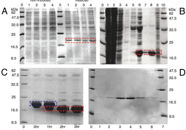
Figure 2.1.1.1. SDS-PAGE overexpression and purification MalF-P2.
Overexpression test of four different cell cultures from four different colonies transformated into BL21 DE3, panel A. Peptide markers are in lane 0 in panels A, C, D with molecular weights marked out in kDa at respective border. Non-induced cell cultures in lanes 1 – 4 to the left and induced cell cultures to the right respectively, after cell lysis. MalF-P2 overexpression is marked with a red dashed box for lanes 1 - 4 of the induced cells. Panel B shows the Ni-NTA-chromatography for MalF-P2. Lanes 1 and 2 show the flow through, lane 3 washing with buffer. Lanes 4 and 5 show the washing with buffer, with 25 mM imidazole added, to prevent unspecific binding. Elution of MalF-P2 with buffer, with 250 mM imidazole added, is shown in lanes 6 – 9. MalF-P2 is marked out with a red dashed box Lane 9 was overloaded for better detection of any residual protein. Thrombin digestion of MalF-P2 at RT is shown in panel C. Lanes 2 - 5 show the digestion of the His6-tag for 0 – 3 hrs of incubation. Full digestion is completed after 3hrs. Red dashed boxes mark His6-tag cut MalF-P2 and blue dashed box the uncut MalF-P2. Panel D shows the purity of collected fractions after MalF-P2 was subjected to a Superdex 75 gelfiltration column.
Purification of MalF-P2 via gravity-flow Ni-NTA-chromatography at 5 0C was successful and showed very low amounts of the target protein in the washing steps and low amount of impurities in the elution step (Figure 2.1.1.1 panel B). Estimated yields for the differently isotopically enriched proteins after purification are listed in Table 2.1.1.1.
Table 2.1.1.1. Protein yields of unlabelled and uniformly labelled MalF-P2.
Yields are in mg/l cell culture after final purification steps.
MalF-P2 unlabelled 15N 15N/2H 15N/13C 15N/13C/2H
yields (mg/l) 21 15 12 14 11
Thrombin cleavage (Amersham Biosciences, Freiburg, D) over night at low temperature 5 0C, showed 100% cleavage of the His6-tag and no protein degradation on SDS-PAGE, with an apparent mass of 21 kDa. All purification steps were done at 5 0C with complete protease inhibitor cocktail tablets (Roche, Mannheim, D), since trace amounts of proteases were always present before gelfiltration.
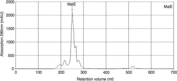
After successful thrombin cleavage (Figure 2.1.1.1 panel C) the protein was subjected to gelfiltration. The FPLC chromatograms show a single sharp peak of MalF-P2 (Figure 2.1.1.2 and 2.1.1.1 panel D). For unknown reasons a small shoulder on the FPLC chromatogram sometimes could be detected. Likely reason could be overload of the column.
Figure 2.1.1.2. FPLC chromatogram MalF-P2.
Gelfiltration chromatography of MalF-P2 subjected on a Superdex 75 gelfiltration, 500ml column on a FPLC. MalF-P2 comes with a retention volume of 273 ml.
MalF-P2 in 20 mM phosphate 100mM NaCl buffer (pH 7.4) was stable for seven days at room temperature at concentrations ranging between 0.1-1 mM. Protein solutions up to 2mM were stable for two days.
A thin band corresponding to a molecular weight smaller than MalF-P2 was always present in SDS-PAGE to a few percents (1 - 3%), of the major band of MalF-P2, before subjected to gelfiltration. Some preparations showed a small shoulder of the MalF-P2 peak in the chromatogram. Fractions containing this shoulder were discarded. A reason for this could be residual amounts of proteases left in the protein solution.
2.1.2 Expression and purification of MalE
Two constructs were used for overexpression of MalE for this study. Early preparations were carried out as described by Daus et al.94. These samples were produced by Mathias Grote (HU Berlin). Later on expressions were carried out at the FMP using the plasmid pCB06, which was provided by Anne Diehl (FMP, Berlin)95. The MalE-His6 plasmid pCB06 were inserted into the E.coli BL21 DE3 <pLysS>
strain and checked for overexpression. Upon IPTG-induction of E.coli BL21 DE3
<pLysS> a very high overexpression of MalE-His6 can be detected from the cytosol by SDS-PAGE, with an apparent mass of ~35 kDa (Figure 2.1.2.1, panel A).
MalE was purified via gravity-flow Ni-NTA-chromatography at 5 0C, thereby taking advantage of the six histidine residues fused to the N-terminus, Figure 1 panel B. The first column wash showed very low amounts of the target protein and low amount of impurities in the elution step. Yields of around 150 mg/l LB culture were achieved after purification.
Figure 2.1.2.1. SDS-PAGE overexpression and purification MalE.
Overexpression test directly into three different colonies, A) lane 1 - 6, after transformation into BL21 DE3 cells. Non-induced cells from colony 1, 2, 3 in lane 1 - 3 respectively. 1hr after induction with IPTG for colony 1 - 3 in lanes 4 -6 respectively. Over expression of MalE is marked out in red dashed box in lanes 4 - 6. Peptide markers are in lane 0 in both panel A and B, with molecular weights marked out in kDa at respective border. Overexpression for the three different scaled up cell cultures, after lysis, can be seen in panel A in lane 7 - 9, non-induced, and in lanes 10 - 12, after 3 hr induction. MalE over expression marked out in red dashed box in lanes 10 - 12. Ni-NTA-chromatography is shown in panel B. Lane 1 and 2 shows the flow through, lane 3 and 4 shows the first 2 washing steps with buffer without Imidazole. Lane 5 - 7 shows washing steps with buffer with 25 mM Imidazole added to prevent any unspecific binding. Elution of MalE with buffer, with 250 mM Imidazole added, can be seen in lanes 8 - 11. Eluted MalE is marked out with red dashed box in lanes 8 - 11.
After successful Ni-NTA elution the protein were subjected to gelfiltration. The FPLC chromatograms show a single sharp peak of MalE (Figure 2). MalE in 20 mM phosphate 100 mM NaCl buffer (pH 7.4) were stable for seven days at room