Edited by:
Irina Goryacheva, Institute for Problems in Mechanics (RAS), Russia
Reviewed by:
Cagatay Basdogan, Koç University, Turkey Emile Van Der Heide, University of Twente, Netherlands
*Correspondence:
Markus Heß markus.hess@tu-berlin.de
Specialty section:
This article was submitted to Tribology, a section of the journal Frontiers in Mechanical Engineering
Received: 29 May 2020 Accepted: 20 August 2020 Published: 21 October 2020
Citation:
Heß M and Forsbach F (2020) Macroscopic Modeling of Fingerpad Friction Under Electroadhesion:
Possibilities and Limitations.
Front. Mech. Eng. 6:567386.
doi: 10.3389/fmech.2020.567386
Macroscopic Modeling of Fingerpad Friction Under Electroadhesion:
Possibilities and Limitations
Markus Heß* and Fabian Forsbach
Institute of Mechanics, Technische Universität Berlin, Berlin, Germany
Electrovibration is one of the key technologies in surface haptics. By inducing controlled electrostatic forces, the friction within a sliding contact between the human finger and a capacitive screen is modulated, which in turn gives effective tactile feedback to the user. Such powerful haptic displays can be built into mobile phones, tablets, navigation devices, games consoles and many other devices of consumer electronics.
However, due to the layered structure and complex material of human skin, the underlying contact mechanical processes have not yet been fully understood. This work provides new continuum-based approaches to macroscopic modeling of the electro-adhesive frictional contact. A solution of pure normal contact between a human finger and a rigid, smooth plane under electroadhesion is derived by applying Shull’s compliance method in the extended regime of large deformations. Based on these results and assuming pressure-controlled friction, a model for the sliding electro-adhesive contact is developed, which adequately predicts the friction force and coefficient of friction over the whole range of relevant voltages and applied normal forces. The experimentally observed area reduction caused by the tangential force is incorporated in a more empirical than profound contact mechanical way. This effect is studied with the help of a two-dimensional finite element model of the fingertip, assuming non-linear elastic material for the skin tissue. Although the simulations are restricted to non-adhesive tangential contacts, they show a significant reduction of the contact area, which is caused by large deformations of the non-linear elastic material around the distal phalanx. This result indicates that adhesion is only of secondary importance for the area reduction.
Keywords: friction, adhesion, electrovibration, surface haptics, finite element method—FEM, compliance method, hyperelastic material
INTRODUCTION
Understanding contact mechanics and friction of human skin is a great challenge for the
tribological community. Human skin is characterized by a complex layered structure of non-linear
viscoelastic material and a specific surface topography. In addition, its hydration level as well as
moisture at its surface can strongly influence grip and touch properties. Especially with regard
to tactile perception skin tribology is not yet fully understood (Derler and Gerhardt, 2012; van
Kuilenburg et al., 2015). In this respect, improved knowledge is urgently needed as it plays a major
role in the rapidly growing field of robotic and haptic applications. One key technology in surface
haptics is electrovibration, which is based on the polarization of a fingerpad pressed in contact
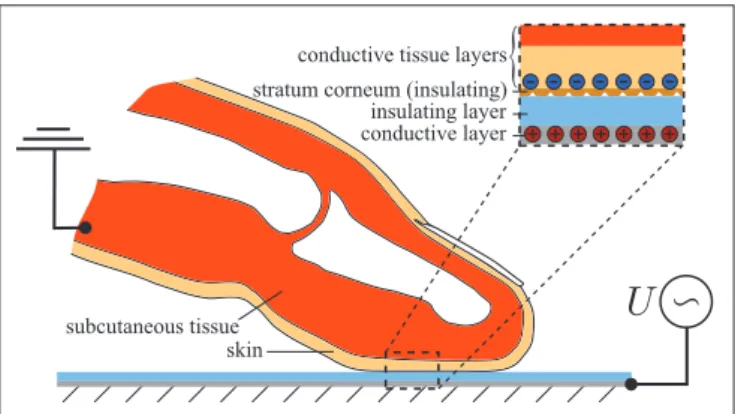
FIGURE 1 | Schematic representation of the electromechanical frictional contact between the index fingertip and touchscreen.
with an AC voltage supplied surface coated by an insulating layer. When the fingerpad is moved over the substrate, the user perceives a characteristic feeling which can be altered by controlling the shape, amplitude and frequency of the voltage (Vardar et al., 2017). In this way, the user can get effective tactile feedback. A schematic representation of such an electromechanical frictional contact between the fingerpad and touchscreen under electrovibration is depicted in Figure 1.
Despite numerous experimental studies in this area, several effects are not yet sufficiently understood (Sirin et al., 2019b).
Above all, there is a lack of well-founded models that correctly reflect the interaction between contact mechanics and electrodynamics. These models should not only provide good results for a single measured quantity like the friction force, but rather all other contact mechanical quantities, particularly the contact area, must also be correctly mapped on the way there.
Excellent modeling from an electrodynamic point of view can be found in the works by Shultz et al. (2015) and Shultz et al. (2018) as well as Nakamura and Yamamoto (2017). From the point of view of contact mechanics, however, the simplest approaches are chosen. Promising multiscale approaches that cover both electrodynamics and contact mechanics in a suitable manner include the works by Persson (2018) and Sirin et al. (2019a).
Following the current Research Topic “contact mechanics perspective of tribology,” we focus exclusively on macroscopic modeling. We define a model as “macroscopic” if it is based on the apparent or ridge contact area. Smaller scales are not taken into account! On this macro scale some effort has been made to map voltage-induced friction as well. In this context, reference is made to Vodlak et al. (2016), Heß and Popov (2019) as well as Argatov and Borodich (2020). The work by Vodlak et al. focus on the assessment of two analytical models of electrovibration based on the parallel-plate capacitor by comparisons with experimental results published in literature.
The approach proposed by Heß and Popov exploits the close analogy of electroadhesive contacts to classical adhesion theories based on van der Waals forces. However, this model provides insufficient results with respect to the contact area as a function of the normal force, since the original theory by Johnson et al.
(1971) is applied. The interesting extension in the work by Argatov and Borodich is that it also takes non-linear elastic material behavior into account. However, a simple Winkler-Fuss model is mainly used, which is why it should generally be checked whether the three-dimensional contact mechanical behavior of the adhesive fingerpad contact can be mapped correctly. During the preparation phase of this manuscript another work on the same topic was published by Basdogan et al. (2020). Their model is based on the original theory of Johnson, Kendall and Roberts applicable for parabolic contacts of linear elastic materials.
Therefore, the inhomogeneous, non-linear elastic finger material is replaced by a (fictive) homogeneous linear elastic one. A further characteristic approach of the model is the assumed proportionality between the real and apparent contact area, which is chosen in accordance with the results of recent multi- scale calculations (Ayyildiz et al., 2018; Sirin et al., 2019a).
As stated above, the aim of the present work is to develop a “macroscale” model which correctly reproduces all contact mechanical quantities and effects arising from the electro-adhesive frictional contact between the fingerpad and touchscreen. Since the tangential contact model is based on the solution of the pure normal contact, it is necessary to derive a robust model for the normal contact under electroadhesion.
Therefore, the present manuscript is structured as follows:
First a novel model for the pure normal contact under electroadhesion is developed by application of the compliance method in the extended regime of large deformations and non- linear elastic materials. The integration of electroadhesion is realized by an idea of Popov and Heß (2018). Based on the resulting function of the ridge contact area in terms of applied voltage and normal force, an extended model for the sliding electro-adhesive contact is developed in Chapter Tangential Contact with Electroadhesion. This chapter begins with a study of the origins of the experimentally observed area reduction in frictional contact by means of adhesion theory and a non- adhesive two-dimensional finite element model of the fingertip accounting for the large deformations and non-linear elastic material behavior. In agreement with the FE results and recent studies, the area reduction is then incorporated in a model for pressure-controlled sliding friction in an empirical way.
Finally, the developed model is compared to recent experimental results. Some conclusive remarks and a short discussion close the manuscript.
NORMAL CONTACT WITH ELECTROADHESION
Although the main objective of this study is to develop a
model for sliding friction of a fingerpad over a smooth surface
under electroadhesion, the preliminary investigation of pure
normal contact is mandatory. The solution of the normal
contact problem must be reproduced correctly in the limit of
a vanishing tangential force, for both cases, with and without
electroadhesion. In particular, the model for calculating the
reduction of the contact area in the state of full slip requires
precise knowledge of the contact area under pure normal loading
with switched-on electroadhesion. While section Theoretical Background is devoted to the repetition and discussion of the theoretical principles to be applied, in section Application to Fingerpad in Contact with Capacitive Screen they are used to solve the normal contact between finger and capacitive screen under electroadhesion.
Theoretical Background
The model for normal contact under electroadhesion is essentially based on two fundamental principles, which are briefly repeated here. From a contact mechanical point of view, the focus lies on Shull’s compliance method, which was originally designed for linear elastic material behavior. Its extended application to non-linear elastic material is not very well-known. According to Heß and Popov (2019), the incorporation of electrostatic attraction into the model is done by calculating the work of electroadhesion as well as the electrostatic force per unit area, which also includes the concept of the equivalent air gap.
Shull’s Compliance Method—Generalized Version of the JKR-Theory
In analogy to the energy-based derivation of the original theory by Johnson et al. (1971), Shull and coworkers (Shull et al., 1998;
Shull, 2002) developed a method which enables obtaining the solution of a more arbitrary adhesive normal contact problem from the known solution of the corresponding non-adhesive one.
This method is called “compliance method” and represents a generalized version of the JKR-theory. Its applicability is neither restricted to homogeneous materials nor to circular contact areas, but linear material behavior is required. The main results of the compliance method are the following expressions for the elastic energy release rate G:
G = (F 1 − F N ) 2 2S 2
dS
dA and G = (δ 1 − δ) 2 2
dS
dA , (1) where F N and δ are the normal force and indentation depth of the adhesive contact. F 1 and δ 1 refer to the values of the corresponding non-adhesive contact and S denotes the contact stiffness defined by:
S : = dF 1
dδ 1 . (2)
After equating the energy release rate G with the thermodynamic work of adhesion w, Equation (1) leads to:
F N (A) = F 1 (A) − S (A) r
2w/ dS
dA , (3)
δ (A) = δ 1 (A) − r
2w/ dS
dA . (4)
Recently Equations (3) and (4) have been rediscovered and more precise restrictions concerning their applicability have been added (Ciavarella, 2018; Popov, 2018). The main assumption is that the sequence of contact configurations in an adhesive contact should be the same as that of contact configurations in a non-adhesive one. For this reason, the method cannot be generally applied to rough contacts. However, in some cases it
seems to provide a good approximation of the adhesive solution.
Furthermore, it should be stressed that the application to non- linear elastic material behavior, which characterizes human skin tissue, is only permitted under certain conditions, which are addressed at the beginning of section Application to Fingerpad in Contact with Capacitive Screen.
Application to power-law relationships between non-adhesive quantities
Typically, experimental results of the non-adhesive fingerpad in normal contact with a smooth rigid plane predict the following power-law relationships between the contact area and normal force as well as indentation depth:
A (F 1 ) = αF 1 m , (5) A (δ 1 ) = βδ n 1 . (6) The corresponding adhesive solution can be obtained from Equations (3) and (4). From Equations (5) and (6) we first determine the stiffness according to Equation (2) by using the chain rule and its derivation with respect to the contact area:
S (A) = n
m β 1/n α − 1/m A 1/m − 1/n , (7) dS
dA = n − m nm
S (A)
A . (8)
After inserting Equations (7), (8) in (3), (4) and taking into account the non-adhesive relationships, the solution of the adhesive normal contact is found:
F N (A) = α − 1/m A 1/m − s
2wn 2
n − m β 1/n α − 1/m A 1 + 1/m − 1/n , (9) δ (A) = β − 1/n A 1/n −
s 2wm 2
n − m β − 1/n α 1/m A 1 − 1/m + 1/n . (10) In particular, Equation (9) is used in section Application to Fingerpad in Contact with Capacitive Screen to calculate both the apparent contact area and the ridge contact area when electroadhesion is switched on. It should be noted that the exponents m and n are generally not independent of one another but are related due to the geometric and material properties of the contact. For instance, for axisymmetric normal contact problems of linear elastic homogeneous half-spaces (with a compact contact area) the exponents are connected by:
m = 2n
n + 2 (11)
and Equation (7) yields the well-known relationship S ∼ √ A.
The classical JKR-theory
As an example, let us rederive the Equations of the classical JKR-
theory. For this purpose, we take the solution of the non-adhesive
contact between two parabolically shaped elastic bodies with
elastic moduli E 1 and E 2 , Poisson’s ratios ν 1 and ν 2 as well as radii
of curvature R 1 and R 2 from Hertz theory. The contact radius is
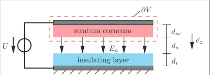
FIGURE 2 | Parallel-plate capacitor model; the dashed line marks the integration domain used for calculation of the electrostatic force.
denoted by a. By a comparison with the predefined relationships (5) and (6) the following parameters can be identified:
m = 2/3, n = 1, β = πR
∗, α = π 3R
∗4E
∗! 2/3
, (12)
where 1
R
∗= R 1
1+ R 1
2and 1
E
∗= 1 − E
1ν
12+ 1 − E
2ν
22. Inserting these parameters into Equations (9) and (10) results in:
F N (a) = 4 3
E
∗a 3 R
∗− p
8πE
∗wa 3 , (13) δ (a) = a 2
R
∗− r 2πwa
E
∗, (14)
which indeed represent the classical JKR solution.
Electrostatic Force and Work of Electroadhesion The most common approach to modeling the electrostatic contact between the fingerpad and the touchscreen is based on the parallel-plate capacitor shown in Figure 2. The conductive tissue of the skin as well as the conductive layer of the screen form the electrodes of the capacitor. Its space is filled by the stratum corneum, an air layer and the insulating layer of the screen. Here, the stratum corneum is assumed to be a perfect non-conducting layer, although it generally has a finite resistivity. However, if we focus on the AC case and the frequency of the applied alternating voltage is high enough, the assumption is justified. For extended approaches from the electrodynamic point of view, which study the frequency-dependence of the frictional force, the reader is referred to the works of Meyer et al. (2013), Vezzoli et al. (2014), and Shultz et al. (2015).
The electrostatic force onto the upper part of the capacitive system consisting of the upper plate and the stratum corneum (see Figure 2) can be calculated from the general definition, that is, by integration of the Maxwell stress tensor T over the surface of the enclosed volume:
−
→ F el = I
∂V
T · d − → A , (15) with T = ε
− → E − → E − 1 2
− → E · − → E
I
, (16)
where − → E denotes the electric field, I is the unit tensor of second order and ε the absolute permittivity. In our simple capacitive
system, the only contribution to the electrostatic force on the upper part comes from the electric field of the air gap − → E a , which points in the z-direction and thus perpendicular to the relevant surface. Therefore, only the zz-component of the Maxwell stress tensor is required to calculate the electrostatic force according to Equation (15), which leads to
−
→ F el = Z
A
T a,zz dA z − → e z = Z
A
1
2 ε a E 2 a dA z − → e z = 1
2 ε a AE 2 a − → e z . (17) From the continuity of the normal component of the electrical displacement at the interfaces between stratum corneum and air as well as air and insulating layer of the screen, the following relationships hold:
ε sc E sc = ε a E a = ε i E i , (18) where the abbreviations “sc” and “i” stand for “stratum corneum”
and “insulating layer,” respectively. In addition, the voltage between the plates can be determined from the line integration of the electrical field, which leads to the following result:
U = E sc d sc + E a d a + E i d i . (19) Herein, d sc , d a , and d i represent the thicknesses of the stratum corneum, air gap and insulating layer of the screen. From Equations (18) and (19) the electric field in the air gap can be determined and after substituting the result into Equation (17) the magnitude of the electrostatic force yields:
F el : =
−
→ F el
= U 2 A
2ε a
d sc
ε sc + d a
ε a + d i
ε i
− 2
= ε 0 U 2 A 2ε r,a
d sc
ε r,sc + d a
ε r,a + d i
ε r,i
− 2
, (20)
where we have introduced the relative permittivities ε r,sc , ε r,a , and ε r,i as well as the permittivity of free space ε 0 on the right side.
After dividing Equation (20) by the plate area, the electrostatic force per unit area is found:
σ el : = F el
A = ε 0 U 2 2ε r,a
d sc
ε r,sc + d a
ε r,a + d i
ε r,i
− 2
. (21)
Analogous to the work of adhesion that comes from the van der Waals forces, the work of electro-adhesion was introduced by Popov and Heß (2018). It represents the required work per unit area to separate the plates and can be calculated by:
w = Z ∞
d
aσ el
d ˜ a
d d ˜ a = ε 0 U 2 2
d sc
ε r,sc + d a
ε r,a + d i
ε r,i
− 1
. (22) Let us briefly take a closer look at the limiting case of
“direct contact,” i.e., a disappearing air gap. The corresponding electrostatic force results from Equation (20) taking into account d a = 0:
F el d a = 0
= ε 0 U 2 A 2ε r,a
d sc
ε r,sc + d i
ε r,i
− 2
. (23)
If we make use of the usual estimation ε r,a ≈ 1, then Equation (23) exactly agrees with the formula proposed by Strong and Troxel (1970) in their pioneering work:
F el ST
= ε 0 U 2 A 2
d sc
ε r,sc + d i
ε r,i
− 2
. (24)
It should be noted that alternative approaches to Equations (24) and (20) were proposed by Kaczmarek et al. (2006) and Vodlak et al. (2016), which are supported by several authors (see e.g., Radivojevic et al., 2012; Giraud et al., 2013; Vezzoli et al., 2014; Liu G. et al., 2018). It goes without saying that these approaches can alternatively be integrated into the new model. Nevertheless, this work makes use of Equations (20–
22). It is assumed that there is always an air gap even in the in-contact state, which includes not only the interstitial spaces between the ridges but also non-contacting areas on smaller length scales resulting from roughness. It is well-known that even the ridges themselves are far away from being smooth. They are punctuated by many concave shaped sweat pores openings.
According to measurements by Liu et al. (2013), the number of sweat ducts considerably varies between subjects and lies between 300 and 1,000 per cm 2 . Therefore, some authors have recently introduced the junction area as a measure of the real contact area (Dzidek et al., 2016). Current purely theoretical investigations using mean-field models based on multiscale contact mechanics take even smaller scales into account which results in a further, significant decrease of the predicted real contact area. A ratio A/A 0 < 10 − 3 is given by Ayyildiz et al. (2018) for instance.
Concept of an equivalent air gap
As mentioned above, the real contact area is made up of various micro-asperity contacts and is generally much smaller than the apparent or ridge contact area. This results in a non-uniform interfacial air gap between the surfaces of the stratum corneum and insulating screen layer. As part of a macroscopic model, we want to capture the whole influence of the non-uniform air gap on the electrostatic force by introducing an equivalent air gap of constant thickness. It is worth noting that the real non-uniform interfacial air gap and thus also the thickness of the equivalent air gap strongly depends on both the normal force and the applied voltage. If the real non-uniform air gap corresponding to a given normal force and voltage were known, the equivalent air gap would be obtained from:
σ el d a,eq
!
= 1 A 0
Z Z
A
0σ el d a x, y
dxdy, (25)
where d a,eq denotes the equivalent air gap. Unfortunately, it is impossible to determine the non-uniform air gap. However, the equivalent air gap concept can be used in another way.
Some scientists calculate the equivalent air gap from accessible experimental data on the frictional force in electroadhesive contacts to incorporate it into a suitable substitute model. For example, Guo et al. (2019) measured the friction force of the finger sliding on a 3M touchscreen at different normal forces but under a fixed apparent contact area. From their experimental results they estimated the electrostatic force, which increased
significantly with increasing normal force. The authors explain this effect through an existing (equivalent) air gap between the fingertip and screen, whose thickness decreases with increasing normal force by a power function. At 150 V peak-to-peak voltage, the thickness decreased from 2.5 to 1.5 micrometers when the normal force has been increased from 0.5 N to 4.5 N. Nakamura and Yamamoto (2016) have proposed a multi-user visuo-haptic system, which integrates an additional rubber-like pad between the fingertip and touchscreen surface that has a surface-insulated electrode on its bottom. By means of an electrically activated and insulated screen electrode an electrostatic force acts on the pad and is then transferred to the fingertip placed on the pad. The electrostatic component to the friction force obtained from measurements showed different behavior at small and large voltages. Thus, they included an equivalent air gap in their parallel-plate capacitor model that varies between 0 and 6 micrometers depending on the applied voltage. We would also like to highlight the work of Shultz et al. (2015), who succeeded in unifying the DC based Johnson Rahbek and AC based electrovibration force models. They clearly show that Coulombic attraction force across the very small interfacial air gap is the origin of both. An alternative possibility is to calculate the thickness of the air gap from knowledge of the measured capacitance, as implemented by Nakamura and Yamamoto (2017) or Shultz et al. (2018). In summary, all the above- mentioned works predict a thickness of the equivalent gap in the order of a few micrometers. Keeping this order of magnitude, the equivalent air gap as a function of the normal force is used in section Sliding Friction to fit the friction force resulting from the tangential contact model onto experimental data.
Application to Fingerpad in Contact With Capacitive Screen
In the following, the developed theoretical principles are applied to the normal contact between the fingerpad and the screen under electrovibration. Therefore, the solution of the corresponding non-adhesive contact is required, whereby “non-adhesive” means that the voltage is turned off. Adhesion due to van der Waals forces are excluded. One critical point must be discussed in advance. The compliance method is based on the principle of superposition, hence its application is restricted to linear elasticity. Human skin, however, shows non-linear material behavior and the contact between finger and screen is associated with large deformations. Although these non-linearities indicate a breakdown of superposition, Lin and Chen (2006) have demonstrated that under comparatively weak adhesion the compliance method can still be applied in the large-deformation regime assuming non-linear elastic materials. In this case, the adhesive part of the solution to be superposed must be understood as a linear perturbation of the non-linear non- adhesive one. Hence, the applicability of this so-called large- deformation JKR (LDJKR) theory is linked to the validity of the assumption:
F N − F 1 (A) δ − δ 1 (A) ≈ dF 1
dδ 1
A
. (26)
By using the finite element method, Lin and Chen (2006) studied two adhesive contact problems involving hyperelastic material:
the contact between a hyperelastic hemisphere and a smooth rigid substrate as well as the contact between a smooth rigid spherical indenter and a hyperelastic half-space. In both cases they checked the accuracy of Equation (26) which actually coincided with the simulation results. Further applications of the LDJKR to Neo-hookean layers can be found in the work by Lin et al. (2008). Without further proof, but based on the above explanations, it is assumed that the compliance method can be applied to the contact between the fingerpad and the screen, too.
The solution of the non-adhesive normal contact between the index finger and screen is required as input for the compliance method. For this purpose, experimental results from accessible literature are used. We focus on the range of small normal forces between 0 and 2 N, which are relevant regarding electrovibration.
Although some reported experimental data in literature vary significantly, there is general consensus that both the dependence of the apparent contact area A 0 and the ridge contact area A R on the normal force can be fitted to power functions according to Equation (5). Given exponents corresponding to the apparent contact area in the low force regime range between 0.36 and 0.42 and those corresponding to the ridge contact area range between 0.42 and 0.58 (Warman and Ennos, 2009; van Kuilenburg et al., 2013a; Lin et al., 2015; Dzidek et al., 2017;
Liu X. et al., 2018). Taking into account that the relationship between area and load depends on many things like the fingerpad inclination angle, measurement methods (ink printing or optical method), environmental conditions (temperature and humidity) and individual properties of the finger (influenced by age and gender of subjects) the differences in exponents are still relatively small. Soneda and Nakano (2010) determined slightly higher exponents from measurements with an optical method, 0.52 for the apparent and 0.68 for the ridge contact area, but they consider a different range of forces lying between 0.1 and 5 N.
For further investigations, values from the work by Dzidek et al.
(2017) are taken, since it also provides the required relationship between the contact area and indentation depth according to Equation (6).
Approach Based on Apparent Contact Area
The measurement results of Dzidek et al. (2017) stem from the left index finger of a 27-year-old female subject.
With regard to the power functions according to Equations (5) and (6), at a finger inclination angle of 30 degrees relative to the smooth countersurface, the following parameters were determined:
m 0 = 0.37, α 0 = 91.9 mm 2 N − m
0, n 0 = 1, β 0 = 64.4 mm 2 − n
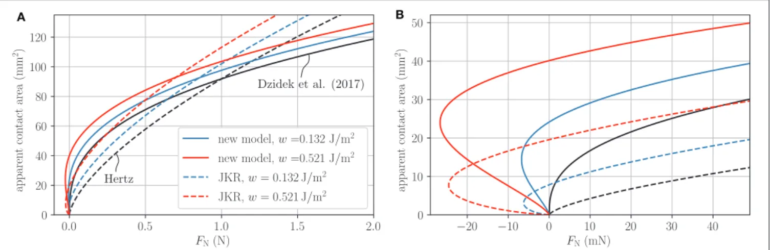
0, (27) where the subscript “0” signifies parameters corresponding to the apparent contact area. After inserting these parameters into Equations (9) and (10), the corresponding solution of the electroadhesive contact is found. In Figure 3, the apparent contact area as a function of the normal force is plotted for
different values of the work of electroadhesion. Curves over the entire loading range are shown on the left, whereas the plot on the right gives an enlarged view of the pull-off region associated with negative loads. The solid black lines represent the original power-law fits to the experimental measurements by Dzidek et al.
(2017). The other two solid lines illustrate the solutions under electroadhesion corresponding to different values of the work of adhesion, w = 0.132 J/m 2 and w = 0.532 J/m 2 . Both are calculated from Equation (22) considering a voltage of 200 V but in one case a realistic equivalent air gap thickness of 1 µm is assumed whereas the other one takes into account unlikely complete contact, characterized by an disappearing equivalent air gap. At first glance, especially if one assumes a moderate air gap thickness, the change in the contact area when switching on the voltage appears so small that one tends to neglect it.
However, it can be clearly seen from Figure 3 on the right that this is not permitted for the range of very small normal forces (combined with higher voltages), which is definitely still of interest for electrovibration. The curve associated with w = 0.132 J/m 2 predicts a pull-off force of 6.74 mN. In addition, the pure voltage-induced contact (no external normal force is applied) creates a contact area of 24.14 mm 2 . Unfortunately, to the best of the authors’ knowledge, no experimental data are available in this interesting range.
The percentage change in the apparent contact area decreases with increasing normal force. At a normal force of 0.5 N, the change is still around 9 %. Nevertheless, in recent measurements by Sirin et al. (2019b) for characteristic normal forces of 0.5 N, 1 N, and 2 N, no significant difference was observed between the (initial) apparent contact areas with and without electrovibration.
Thus, it can be assumed that switching on the voltage only results in an enlargement of the ridge contact area. This is the main reason why we decided to develop a model based on the ridge contact area instead of the apparent one.
Approach Based on Ridge Contact Area
Under the assumption that the LDJKR theory remains valid for applications to contact problems involving non-linear elastic human skin material, we were able to derive a solution for the electro-adhesive contact between the finger and the screen. It was tacitly assumed that the apparent contact area is compact and approximately circular. The applicability of the LDJKR theory to the ridge contact area requires an additional, very strict assumption. As previously mentioned, each contact area configuration under electroadhesion must be the same as that of the corresponding non-adhesive contact loaded by an appropriately chosen higher normal force (Ciavarella, 2018;
Popov, 2018). This condition is definitely not fulfilled here!
However, since more suitable simple methods do not exist, the compliance method is used once again to obtain a (rough) approximate solution.
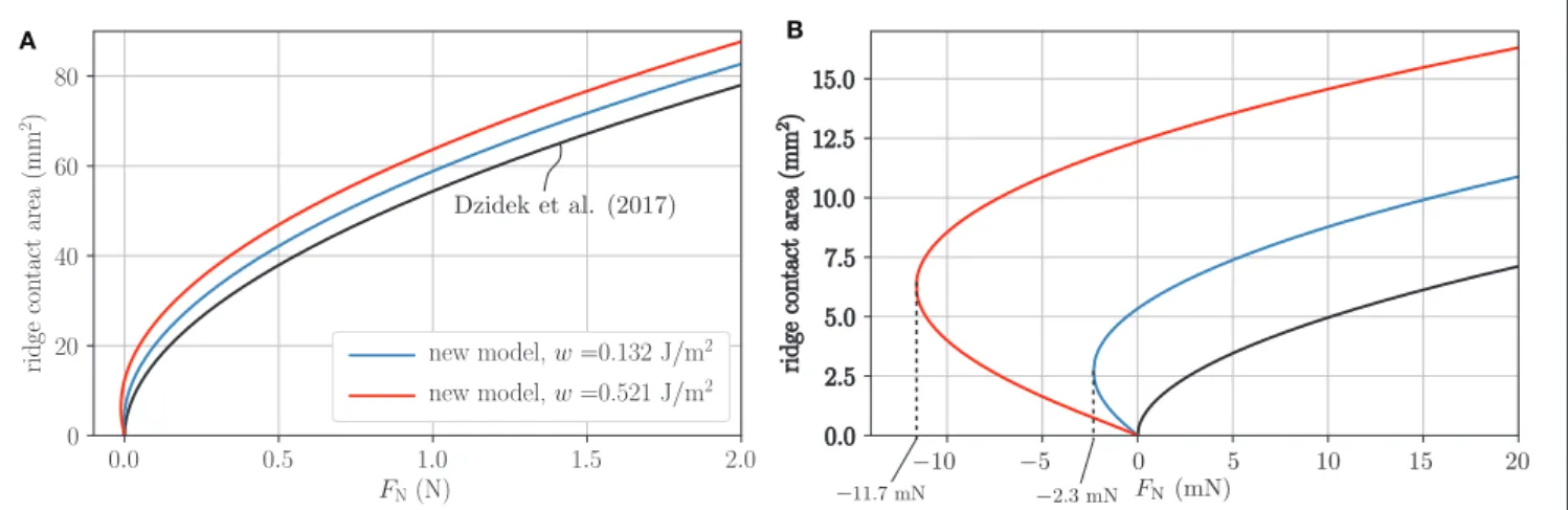
In the following, we proceed in exactly the same way as in the last section. First, the parameters for the power functions are taken from the work by Dzidek et al. (2017).
m R = 0.52, α R = 54.9 mm 2 N − m
R, n R = 1.41, β R = 33.3 mm 2 − n
R,
(28)
A B
FIGURE 3 | Apparent contact area as a function of normal load for different works of electroadhesion; black curves represent the non-adhesive solution; (A) Plot over the whole loading range; (B) Enlarged view of the pull-off region associated with negative loads.
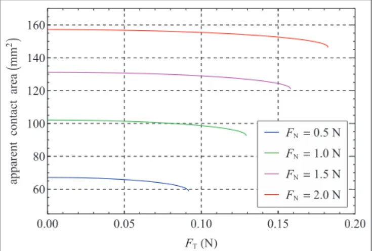
where the subscript “R” indicates parameters corresponding to the ridge contact area. Subsequently, these parameters are inserted into Equations (9) and (10) which yields the solution under electroadhesion. The ridge contact area as a function of the normal force is plotted in Figure 4, again distinguishing between the three characteristic cases: non- adhesive contact, contact under electroadhesion taking into account an equivalent airgap of 1 µ m as well as complete contact associated with a vanishing equivalent air gap.
In the latter two electroadhesive cases, pull-off forces of 2.3 and 11.7 mN are obtained, as illustrated by Figure 4B. The change in the ridge contact area at a normal force of 0.5 N reads 11.2% for an air gap of one micron and 23.8% for complete contact.
As already stated, there appears to be no experimental data in the literature to evaluate the quality of our model and adjust the equivalent air gap thickness from it. In this context, however, we would like to point out that models based on Hertz or the original JKR theory assuming a parabolic profile and a constant equivalent elastic modulus cannot map the apparent or ridge contact area as a function of the normal force correctly. To show this, the apparent contact area for the cases of Hertz and original JKR [see Equation (13)] are included in Figure 3. The effective radius was estimated with R
∗≈ 1 cm and an effective elastic modulus of E
∗≈ 47.4 kPa is chosen such that the apparent contact areas for the non-adhesive normal contact agree at F N = 1 N. The values for the work of (electro-)adhesion are chosen as for the new model. The Hertzian prediction differs significantly from the experimentally verified non-adhesive curve by Dzidek et al. (2017). Of course, these large differences are inherited in the JKR cases. At most, Hertz based models that take into account an equivalent effective elastic modulus that varies with the contact area (or indentation depth) would be qualified for modeling (van Kuilenburg et al., 2013a,b). Nevertheless, such models would still have to be suitably expanded to include the effect of electroadhesion.
TANGENTIAL CONTACT WITH ELECTROADHESION
A suitable, macroscopic model for mapping the electroadhesive frictional contact between the fingerpad and screen should fulfill three main characteristics:
I. It should be based on a model for normal contact under electroadhesion.
II. It must be able to reproduce the experimentally observed contact area reduction caused by the frictional force in the state of full slip.
III. It requires a macroscopic approach for the frictional force.
Regardless of these specifications, the quality of a model can only be ensured by experimental verification of all relevant correlations. To meet the first point, the normal contact model based on the ridge contact area presented in section Application to Fingerpad in Contact with Capacitive Screen is applied. It is essentially described by Equation (9) with exponents m R = 0.52 and n R = 1.41 originating from the experiments by Dzidek et al.
(2017). The occurring work of electroadhesion w is defined by Equation (22).
To satisfy requirement II, most current studies exploit adhesion theories based on fracture mechanics concepts. For this reason, section Tangential Contact under Full Stick assumption—
Peeling starts with a discussion about peeling. However, by means of simulations with a two-dimensional FE model of the fingertip in section Transition from Stick to Slip—the Evolution of Contact Area in the Non-adhesive Case, it is shown, that the area reduction is mainly caused by large deformations of the non-linear elastic material around the distal phalanx. Therefore, in consistence with the FE results and available experimental investigations by Sahli et al. (2018) the area reduction is incorporated empirically [see Equation (43)].
On the defined macroscopic scale, a pressure-controlled
friction law is assumed in section Sliding Friction. In connection
with the specific parameter optimization, this leads to a good
A B
FIGURE 4 | Ridge contact area as a function of normal load for different works of electroadhesion; black curves represent the non-adhesive solution; (A) Plot over the whole loading range; (B) Enlarged view of the pull-off region associated with negative loads.
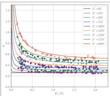
agreement of the friction force and the friction coefficient with experimental data. However, the incorporation of extended approaches consisting of both a pressure-based and an adhesion- based term is in principle possible.
Tangential Contact Under Full Stick Assumption—Peeling
Most current theoretical studies on tangential contacts of soft materials try to explain the experimentally observed contact area reduction by fracture mechanics concepts. They focus on the adhesive contact between elastically similar materials loaded by a small tangential force that does not cause any slip in the contact area. Under this full-stick condition all material points within the contact area undergo the same tangential displacement δ T with respect to points remote from the contact area. In this case, the compliance method can easily be extended by including corresponding energetic terms to the elastic strain energy as well as the mechanical potential energy of the external load. This results in an energy release rate given by:
G = (F 1 − F N ) 2 2S 2
dS dA + F T 2
2S T 2
dS T
dA and G = (δ 1 − δ) 2
2 dS dA + δ T 2
2 dS T
dA (29)
where S T : = dF T /dδ T denotes the tangential contact stiffness.
After setting the energy release rate G equal to the work of (electro)adhesion w the general solution of the (no-slip) tangential contact under electroadhesion is obtained. Note, that the applicability of the extended compliance method is neither restricted to homogeneous materials nor to the half- space approximation or circular contact areas, but linear material behavior is required. In principle, the same requirements apply as for the theory of pure normal contact with adhesion. In this context, Equation (29) represents a novelty to the best of the authors’ knowledge. Unfortunately, its applicability to non-linear elastic materials is constrained by very small tangential forces.
Since the tangential stiffness of the contact does not emerge from any literature, a direct extension of the promising results for the normal contact with adhesion from section Application to Fingerpad in Contact With Capacitive Screen is not readily possible. In order to discuss the influence of the tangential force on the apparent contact area between the finger and the screen, the (homogenized) Hertzian-based contact model is used as a rough approximation instead. In this case the normal and tangential contact stiffness read (Popov et al., 2019).
S (A 0 ) = 2E
∗r A 0
π , S T (A 0 ) = 2G
∗r A 0
π with 1
G
∗: = 2 − ν 1
4G 1 + 2 − ν 2
4G 2
. (30)
By substituting the results of Equation (30) into Equation (29) and taking into account G = w, the apparent contact area as a function of the applied external forces is determined after some rearranging
A
0(F
T, F
N) = π
3R
∗4E
∗
F
N+3πR
∗w + s
6π R
∗wF
N+ 9π
2R
∗2w
2− E
∗G
∗F
T2
2/3