Silicon, Titanium and Iron Oxides by Plasma Enhanced Chemical Vapor Deposition for Solar
Water Splitting
Inaugural-Dissertation zur Erlangung des Doktorgrades
der Mathematisch-Naturwissenschaftlichen Fakultät der Universität zu Köln
vorgelegt von Myeongwhun Pyeon aus Yeonggwang, Süd Korea
Köln, 2018
Die vorliegende Arbeit wurde im Zeitraum von April 2014 bis October 2018 am Lehrstuhl für Anorganische und Materialchemie an der Universität zu Köln unter Anleitung von Prof. Dr.
Sanjay Mathur angefertigt.
Berichterstatter: Prof. Dr. Sanjay Mathur Prof. Dr. Mathias Wickleder Prof. Dr. Taejin Hwang Vorsitzender: Prof. Dr. Klas Lindfors Tag der mundlichen Prufung: 23.11.2018
Dedicated to my parents
Acknowledgement
I thank Prof. Dr. Sanjay Mathur for his admission to PhD study in AK Mathur. He has been providing me priceless opportunities and encouragement not only as a supervisor but also as a mentor. I believe that great atmosphere in the working group reflects his warmth and friendly eagerness for discussing with students. In the same breath, my special gratitude goes to Prof. Dr.
Taejin Hwang whom I respect in scientific and in philosophical standpoints. I owe him lots of patience he made to educate and to inspire me. I appreciate Prof. Dr. Mathias Wickleder for being an examiner willingly of my thesis despite very late request. It is my great honor to have Prof. Dr. Sanjay Mathur (supervisor), Prof. Dr. Taejin Hwang (co-supervisor) and Prof. Dr.
Mathias Wickleder (examiner) as a committee for my PhD defense.
Dr. Yakup Gönüllü deserves to be highly acknowledged who was willing to be a friend of people working in the group rather than a colleague or a leader. His organization skill and scientific experience on PECVD and metal oxides helped me plan experimental works and sorting data well in the beginning of my study. I appreciate Dr. Ashish Lepcha for his hospitality and sacrifice he showed whenever I need some help, which let me feel like home and keep up with my works throughout my stay in AK Mathur. His invitations to dinner were always great where we could build intimate relationship having nice conversation on daily life, cultural background and of course research works, etc. Besides, I would like to thank Dr. Corinna Hegemann, Dr. Lisa Czympiel and Dr. Thomas Fischer for their dedication to organization.
Specifically in research works, Dr. Meng Wang was an outstanding researcher who led me to the concept of PEC water splitting. Thanks to him, I could reach the field with fewer obstacles. I also must acknowledge Dr. Meenal Deo and Mr. Mehmet Gürsoy who actively participated in the subgroup, called plasma group. Dr. Deo supported my works by advising on scientific and technical aspects with full of responsibility. Mr. Gürsoy who has excellent understanding on PECVD shared his precious experience and knowledge with us, which led to meaningful achievement in magnets-assisted PECVD for Fe2O3 and SiOx films. Moreover, I would like to thank Dr. Tero-Petri Ruoko who introduced a new and a strong tool to verify kinetics of photocarriers which is TAS (transient absorption spectroscopy). Based on his experience and specialty on TAS, we could obtain better insights and possibility for further works in PEC water splitting. All of these collaborative works were realized by being active international characteristics of the working group. An additional remark goes to Ms. Nürgul Tosun who arranged microscopic analyses, Ms. Ruth Bruker for contribution to SEM images with full of skills and experience, technicians working in the Werkstatt (it is so shameful for me not to know
their names) for fabricating experimental equipment with excellence and Mr. Mustafa Demirbilek the Werkmeister for maintaining facilities.
I can’t miss to mention about friends working together under the name of AK Mathur especially in the plasma lab. Mr. Alexander Möllmann and Mr. Danny Bialuschewski perform excellent works based on their enthusiasm and hard working. In addition, I should express my gratitude to Dr. Jennifer Leduc, Ms. Aida Raauf, Mr. Eunhwan Jung, Rishabh Garg, Senol Ö z, Karim Arroub, Ufuk Atamtürk, and Daniel Stadler for having fun and serious conversation which was one of the most important aspects staying abroad. I also admire their attitude to integrate people into the group without any prejudice, which I could feel comfortable and rely on them. Although I can’t name the entire group members, I must show my best respect to colleagues who volunteer to operate analytic tools, study themselves about the machines and support the others. And I would like to acknowledge the members who sacrificed and volunteered to take responsibilities for inner/outer events that impressed numerous people. Within those scientific activities, I witnessed a lot of positive aspects of colleagues like integration, altruism and self-motivation, which affected me.
Most of all, my family, the reason why I am, I thank you.
Abstract
This study focuses on the synthesis and modification of silicon, titanium and iron oxides using PECVD (plasma enhanced chemical vapor deposition). The motivation for this work resulted from the urgent need for alternative energy solutions and demand for functional coatings. More detailed, thin films of semiconducting metal oxides (α-Fe2O3, TiO2) were prepared and modified to be applied for photoelectrochemical (PEC) water splitting (WS) that has been regarded as a promising approach to eco-friendly generation of hydrogen from sea water. Main efforts were put into the improvement of the PEC performance, represented by photocurrent density and onset potential in linear scan voltammetry by three experimental strategies.
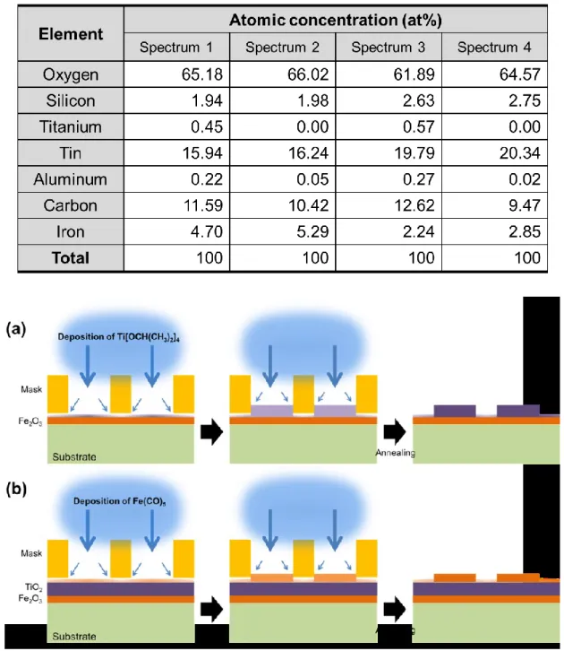
The first strategy was to fabricate heterojunctions, consisting of Fe2O3 (representing α-Fe2O3, hematite) and TiO2. A distinctive structure of heterojunction photoelectrodes was fabricated by employing a striped metal mask during PECVD, in order to achieve macrostructuring. Double- layered TiO2//Fe2O3:FTO electrodes with striped structures of TiO2 and triple-layered Fe2O3//TiO2//Fe2O3:FTO electrodes with orthogonal cross-bar structures were produced.
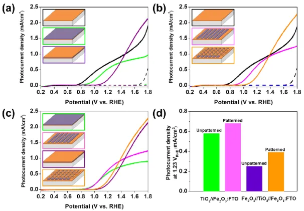
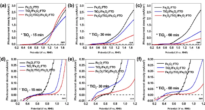
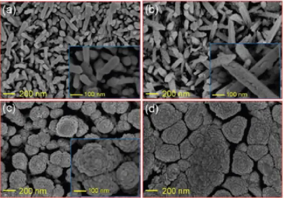
Although neither the double nor triple layered electrodes showed enhanced PEC performances compared to single-layered Fe2O3 photoanodes, most likely due to increased interfacial recombination, patterned double and triple heterojunction photoelectrodes showed increased photocurrent densities of approximately 17 % and 56 %, respectively, compared to the unpatterned ones (0.58 mA/cm2 for the double layer and 0.25 mA/cm2 for the triple layer at 1.23 V vs. reversible hydrogen electrode (RHE)). This could be attributed to the coexistence of Fe2O3 and TiO2 with characteristic surface morphology in contact with electrolyte as well as to unintentional elemental doping. In addition to the planar heterojunction, hematite nanorods synthesized by a hydrothermal route were covered with PECVD grown TiO2. It appeared that TiO2 nanoparticles were homogeneously deposited onto hematite nanorods, forming a core-shell structure with a Fe2O3-TiO2 heterojunction. The highest photocurrent density (0.74 mA/cm2 at 1.5 V vs. RHE) was obtained from a Fe2O3-TiO2 photoanode where the deposition time for TiO2 was 30 min, while the pristine hematite nanorods and the PECVD grown TiO2 (30 min) photoanodes exhibited 0.19 mA/cm2 and 0.04 mA/cm2, respectively, under similar electrochemical conditions.
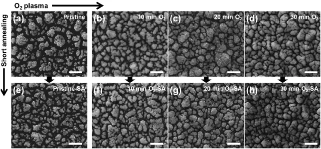
Secondly, PECVD was utilized not only to produce hematite thin film but also to alter surface chemical states by post-deposition treatment of films with oxygen plasma, followed by rapid thermal treatment (referred as “short annealing” in the main text). Oxygen plasma treatments led to significant changes in the microstructure of hematite surfaces, exhibiting that growth of
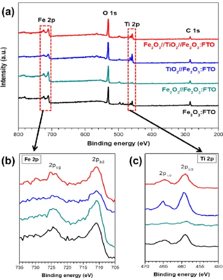
particles was promoted as the treatment duration increased. Moreover, XPS (X-ray photoelectron spectroscopy) analysis used to investigate the surface chemical states, showed a shift to lower binding energies, suggesting an interaction of Fe atoms with surface adsorbed oxygen species.
These altered chemical states at the hematite surface seemed to be responsible for the onset potential shift in anodic direction that indicates sluggish oxidation on the surface, which was corroborated by TAS (transient absorption spectroscopy). However, upon the rapid thermal treatment, recovery in chemical shift was observed, indicating rearrangement of surface states and suggesting that chemisorbed oxygen is not an integral part of the hematite lattice. More interestingly, the onset potential moved back to the level of the untreated photoanode. It strongly indicates that the surface chemical states are highly influential forwards water oxidation at the photoanode/electrolyte interface in PEC water splitting reaction. Furthermore, an increased photocurrent density of up to 2-fold was observed from the sample treated with both oxygen plasma and short annealing compared to the pristine hematite photoanode.
The third approach involved modulation of plasma using external magnetic fields in PECVD processes based on the assumption that plasma confinement would affect the deposition kinetics.
As a result, morphology and crystallinity of the hematite films remarkably varied depending on the characteristics of applied magnetic fields such as magnetic polarity and geometry of magnetic flux. In this study, two types of magnets having different geometry, i.e. rod-type and disk-type, were employed and the investigation was conducted to evaluate the influence of magnetic fields. The hematite film deposited under the repulsive magnetic field induced by the rod-type magnets produced hematite particles orthogonally grown to the substrate, leading to a porous structure while the one produced under the attractive field showed a densely packed surface and a suppressed (110) crystalline plane, revealed by XRD (X-ray diffraction) analysis.
Likewise, when the hematite films were grown in the presence of magnet stacks (3 disk-type magnets), more compact surfaces were obtained than the reference hematite sample. Moreover, in terms of crystallinity, samples grown in repulsive and attractive arrangement of magnets exhibited (104) plane became dominant with decreased signal of the (110) plane. When those hematite films were evaluated for PEC water splitting, the ones deposited under magnetic fields regardless of types of magnets used, generated more photocurrent density than the reference hematite photoanode did. Thus, the effectiveness of magnet-assisted PECVD for modulating hematite films was verified as a potential strategy to improve the functional performance of photoanode materials. In another set of experiment, PECVD processes with hexamethyldisiloxane (C6H18OSi2, HMDSO) for the deposition of SiO2-like (SiOx or SiOC) films was conducted. It was revealed that the deposition rate and surface hydrophobicity of SiOx
was increased with magnet-assisted PECVD. A higher water contact angle was attributed to increased surface roughness and surface carbon content revealed by AFM (atomic force microscopy) and XPS, respectively.
Kurzzusammenfassung
Diese Arbeit konzentriert sich auf die Synthese und Modifizierung von Silizium-, Titan- und Eisenoxiden mithilfe von PECVD (Plasma-gestützte chemische Gasphasenabscheidung), um den Bedarf an alternativen Energielösungen abzudecken, sowie die Anforderungen an funktionellen Beschichtungen zu untersuchen. Im Detail wurden dünne Filme aus halbleitenden Metalloxiden (α-Fe2O3, TiO2) hergestellt und modifiziert, um sie für die photoelektrochemische (PEC) Wasserspaltung (WS) zu verwenden, die als vielversprechender Ansatz zur umweltfreundlichen Wasserstofferzeugung ausgehend von Meerwasser angesehen wird. Im Fokus stand die Verbesserung der PEC-Leistung basierend auf der Photostromdichte und dem Onset-Potential in der linearen Scan-Voltammetrie, welches durch drei experimentelle Strategien überprüft werden sollte.
Die erste Strategie war die Herstellung von Heteroübergängen, bestehend aus Fe2O3 (α-Fe2O3, Hämatit) und TiO2. Photoelektroden mit Makrostrukturierung und einem Heteroübergang wurden hergestellt, indem eine gestreifte Metallmaske während des PECVD-Prozesses verwendet wurde. Eine doppelschichtige TiO2//Fe2O3:FTO-Elektrode mit einer Streifenstruktur aus TiO2 und eine dreischichtige Fe2O3//TiO2//Fe2O3:FTO-Elektrode mit orthogonaler Crossbar- Struktur wurden hergestellt. Obwohl weder die Doppel- noch die Dreifachschicht eine verbesserte PEC-Leistung im Vergleich zu einer monolagigen Fe2O3-Photoanode aufwiesen, zeigten die strukturierten Doppel- und Dreifach-Heteroübergangs-Photoelektroden eine erhöhte Photostromdichte bei 1,23 V gegenüber einer reversiblen Wasserstoffelektrode (RHE) von etwa 17% und 56% im Vergleich zu den unstrukturierten (0,58 mA/cm2 für die Doppelschicht und 0,25 mA/cm2 für die Dreifachschicht). Dies könnte auf die Koexistenz von Fe2O3 und TiO2 mit der charakteristischen Oberflächenmorphologie im Kontakt mit dem Elektrolyten sowie auf die unbeabsichtigte Elementdotierung zurückgeführt werden. Zusätzlich zum planaren Heteroübergang wurden Hämatit-Nanostäbe, die auf hydrothermalem Weg synthetisiert wurden, mit PECVD-gewachsenem TiO2 bedeckt. Es zeigte sich, dass TiO2-Nanopartikel homogen auf Hämatit-Nanostäbchen abgeschieden wurden und eine Kern-Schalen-Struktur von Fe2O3-TiO2- Heteroübergängen gebildet wurden. Die höchste Photostromdichte (0,74 mA/cm2 bei 1,5 V gegen RHE) wurde mit einer Fe2O3-TiO2-Photoanode erhalten, wobei die Abscheidungszeit für TiO2 30 Minuten betrug, während die unbehandelten Hämatit-Nanostäbe und die PECVD- hergestellten TiO2-Photoanoden (30 min) nur 0,19 mA/cm2 bzw. 0,04 mA/cm2 unter ähnlichen elektrochemischen Bedingungen zeigten.
Zweitens wurde die PECVD auch zur Veränderung der chemischen Oberflächenzustände durch
Nachbehandlung von Filmen mit Sauerstoffplasma eingesetzt. Das Sauerstoffplasma führte zu einer signifikanten Veränderung der Mikrostruktur an der Hämatitoberfläche, was zeigte, dass das Wachstum von Partikeln mit zunehmender Behandlungsdauer gefördert wurde. Darüber hinaus zeigten chemische Zustände, die durch XPS (Röntgenphotoelektronenspektroskopie) detektiert wurden, eine Verschiebung zu einer niedrigeren Bindungsenergie, was auf eine Wechselwirkung von Fe-Atomen mit oberflächenadsorbierten Sauerstoffspezien hindeutet. Diese veränderten chemischen Zustände der Hämatitoberfläche scheinen für die Verschiebung des Anfangspotentials in anodischer Richtung verantwortlich zu sein, was auf eine träge Oxidation an der Oberfläche hindeutet, welches durch TAS (Transiente Absorptionsspektroskopie) bestätigt wurde. Bei der schnellen thermischen Nachbehandlung wurde jedoch eine Erholung der chemischen Verschiebung beobachtet, was auf eine Umordnung der Oberflächenzustände hindeutet und nahelegt, dass chemisorbierter Sauerstoff kein integraler Bestandteil des Hämatitgitters ist. Interessanterweise bewegte sich das Anfangspotential wieder auf das Niveau der unbehandelten Photoanode. Es zeigt stark an, dass die chemischen Zustände der Oberfläche einen starken Einfluss auf die Wasseroxidation an der Photoanoden/Elektrolyt-Grenzfläche in der PEC-Wasserspaltungsreaktion haben. Darüber hinaus wurde eine erhöhte Photostromdichte von bis zu dem 2-fachen Wert der Probe beobachtet, die sowohl mit Sauerstoffplasma als auch mit kurzem Tempern behandelt wurde, verglichen mit der ursprünglichen Hämatit-Photoanode.
Der dritte Ansatz umfasste die Modulation von Plasma unter Verwendung von externen Magnetfeldern in den PECVD-Prozessen basierend auf der Annahme, dass die Plasmaeingrenzung die Ablagerungskinetik beeinflussen würde. Als ein Ergebnis variierten die Morphologie und die Kristallinität der Hämatitfilme bemerkenswert in Abhängigkeit von den Eigenschaften der angelegten Magnetfelder, wie der magnetischen Polarität und der Geometrie des magnetischen Flusses. In dieser Studie wurden zwei Arten von Magneten mit unterschiedlichen Geometrien, d. h. Stab- und Scheiben-Typ, verwendet, und die Untersuchung wurde durchgeführt, um den Einfluss von Magnetfeldern zu bewerten. Die Abscheidung, welche unter dem von den stabförmigen Magneten induzierten abstoßenden Magnetfeld durchgeführt wurde, erzeugte Hämatitpartikel, die orthogonal zum Substrat gewachsen waren, was zu der Bildung einer porösen Struktur führte, während bei dem Anziehungsfeld eine dicht gepackte Oberfläche mit unterdrückter (110)-Kristallebene entstand, welches durch XRD Analyse (Röntgenbeugung) gezeigt wurde. Wenn die Hämatitfilme in Gegenwart von Magnetstapeln (3 Scheibenmagnete) gezüchtet wurden, wurden in ähnlicher Weise kompaktere Oberflächen erhalten als bei der Referenz-Hämatitprobe. Im Hinblick auf die Kristallinität zeigten Proben, die in einer abstoßenden und anziehenden Anordnung von Magneten gewachsen waren eine
dominantere (104)-Ebene und ein verringerten Signal in der (110)-Ebene. Diese Hämatitfilme wurde mittels PEC-Wasserspaltung untersucht und die Elektroden, welche unter Magnetfeldern (unabhängig von der Art der verwendeten Magnete) abgeschieden wurden, wiesen eine höhere Photostromdichte als die der Referenz-Hämatit-Photoanode auf. Daher wurde die Wirksamkeit der magnetunterstützten PECVD zur Modulation von Hämatitfilmen als eine mögliche Strategie zur Verbesserung der funktionellen Leistungsfähigkeit von Photoanodenmaterialien verifiziert. In einer anderen Versuchsreihe wurde ein PECVD-Prozess mit Hexamethyldisiloxan für einen SiO2-ähnlichen (SiOx oder SiOC) Film durchgeführt. Es zeigte sich, dass die Ablagerungsrate und Oberflächenhydrophobie von SiOx mit magnetunterstütztem PECVD erhöht wurde. Ein höherer Wasserkontaktwinkel wurde der erhöhten Oberflächenrauigkeit und dem Oberflächenkohlenstoffgehalt zugeschrieben, die durch AFM (Rasterkraftmikroskopie) bzw.
XPS detektiert wurden.
Table of Contents
1 Introduction... 1
1.1 Chemical vapor deposition (CVD) ... 4
1.2 Plasma enhanced chemical vapor deposition (PECVD)... 7
1.2.1 Plasma characteristics ... 7
1.2.2 Gas phase plasma-chemical reactions ... 8
1.2.3 Surface reactions in PECVD ... 13
1.2.4 Applications of PECVD grown thin films... 13
1.3 Metal oxides ... 17
1.3.1 Functional metal oxides synthesized by a variety of routes ... 17
1.3.2 Targeted applications of PECVD metal oxides ... 18
1.4 Photoelectrochemical (PEC) water splitting ... 19
1.4.1 Mechanism and background ... 19
1.4.2 State-of-the-art and literature survey ... 21
1.5 Hydrophobic coatings ... 24
1.5.1 Mechanism and background ... 24
1.5.2 State-of-the-art and literature survey ... 25
2 Synthesis of heterojunction Fe2O3-TiO2 films ... 29
2.1 Motivation and background ... 29
2.1.1 Design of heterojunction Fe2O3-TiO2 photoelectrodes for PEC water splitting ... 29
2.1.2 Core-shell structured heterojunction of Fe2O3-TiO2 photoelectrodes ... 39
3 Surface modification of hematite films by post-treatments ... 43
3.1 Motivation and background ... 43
3.1.1 Post-synthesis treatment of hematite via oxygen plasma ... 43
3.1.2 Post-synthesis treatment of hematite via argon plasma ... 52
4 In-situ modulation of thin film growth by external magnetic fields ... 57
4.1 Motivation and background ... 57
4.1.1 Effect of magnetic fields on a magnetic oxide (hematite) ... 58
4.1.2 Effect of magnetic fields on a non-magnetic oxide (SiOx) ... 70
5 Experimental ... 77
5.1 Synthesis of heterojunction Fe2O3-TiO2 films ... 77
5.1.1 Design of heterojunction Fe2O3-TiO2 photoelectrodes for PEC water splitting ... 77
5.1.2 Core-shell structured heterojunction of Fe2O3-TiO2 photoelectrodes ... 78
5.2 Surface modification of hematite films by post-treatment ... 79
5.2.1 Post-treatments of hematite films via oxygen/argon plasma and short annealing ... 79
5.3 In-situ modification of metal oxides via magnetic field assisted PECVD ... 79
5.3.1 Effect of magnetic fields on hematite photoelectrodes for PEC water splitting ... 79
5.3.2 Effect of magnetic fields on surface functionality of SiOx films ... 82
5.4 Characterization methods ... 82
6 Summary and outlook ... 85
7 References ... 89
8 Indices ... 101
8.1 Figures index ... 101
8.2 Schemes index ... 103
8.3 Tables index ... 104
9 Appendix ... 107
9.1 Abbreviations (in order of appearance) ... 107
9.2 Lebenslauf ... 109
9.3 Publication list ... 110
9.4 Presentations... 111 Erklärung ... 113
1 Introduction
Hydrogen both in industry and research fields has drawn tremendous attention as a promising alternative energy carrier, which enables to store and to distribute sustainable energy sources.
Due to its abundance in nature and production of carbon-free by-products, development of technologies attracts and motivates research fields to realize “Hydrogen Economy”1 in the future.
Currently, over 95 % of hydrogen is produced from fossil-fuels such as natural gas, oil or coal worldwide. For example, hydrogen production in US mainly relies on steam methane reforming and the annual production exceeded 5,000 tons in the industrial marketplace.2 Upon increasing concern about reducing carbon-based by-products to decelerate air pollution, a breakthrough in development of hydrogen production became an utmost topic.
Solar energy-driven splitting of water is one of the promising methodologies, which utilizes semiconducting materials The term photoelectrochemical (PEC) water splitting that is widely used is derived from its concept that charge carriers “photo”generated by solar irradiation are involved to “electrochemical” redox reactions that split water molecules into hydrogen and oxygen. To realize an efficient PEC water splitting system, it is necessary to address several prerequisites in materials selection. Since the PEC water splitting system consists of photoelectrods in contact with aqueous electrolyte under solar irradiation, chemical stability is highly required. The reason for using aqueous electrolyte is due to the fact that pure water with high electrical resistance impedes protons and hydroxide ions to be mobile enough. Typical electrolytes can have wide range of pH.3 In terms of electronic structures, photoelectrode materials need to possess appropriate energy band gap (Eg) to efficiently absorb solar irradiation and their band edges (valence and conduction bands) should position properly (Detailed discussion will be given in 1.4). Scheme 1 depicts several aspects to be considered for development of new photoelectrode materials for PEC water splitting, which describes that the successful expansion in development of the optimum photoelectrodes relies on interplay between understanding, engineering the materials and development of PEC systems.
Scheme 1 Complex interplay of material properties and device integration in the
development of new materials for photoelectrochemical water splitting (PEC-WS) reactions.
Works in this thesis mainly deal with deposition and modification of metal oxides synthesized by PECVD for PEC water splitting. Thanks to intense efforts delivered in the working group, a major part of works is focused on modification strategy to verify effectiveness of several idea- based approaches on targeted functionalities (PEC water splitting and hydrophobicity for α- Fe2O3 (hematite) and SiOx, respectively) utilizing a PECVD technique. Thus, this report consists of general descriptions of CVD (chemical vapor deposition) that will provide background information starting from a mechanism of gas phase reactions to form thin films. Then, this will be extended into the PECVD that is one of the modified forms of a conventional thermal CVD.
The section providing introduction to PECVD highlights from fundamental plasma chemistry which is essential in plasma reactions to applications of exemplary PECVD grown films. In addition to process-related aspects, following sections will cover the specific applications of PEC water splitting and surface hydrophobicity, which point out state-of-the-art of each application and challenges. Prior to discussions on mechanistic characteristics of gas phase chemical deposition, a comparison of some processes for thin film fabrication is provided in the following sections.
Among a number of processes to produce functional coatings in research and in industry,
PECVD is widely known as an advantageous technique that overcomes several limitations which wet-chemical processes and other gas phase depositions such as PVD (physical vapor deposition) and thermal CVD have faced in synthesis of thin films. For instance, PECVD is a favorable method to deposit thin films on a wide range of substrates including temperature sensitive substrate, e.g. polymer that is not applicable to unmodified CVD due to high temperature process.
Besides, substrates with sophisticated geometry can be used in PECVD owing to isotropic chemical reaction in plasma whereas films formation in thermal CVD takes place along a direction of precursor transport, which limits the use of substrates with a complex 3-D structure.
Table 1 provides a list of characteristics of typical methods used for film fabrication.4,5 Table 1 A comparison list of various techniques applied for fabrication of thin films.
Practically, in preparation of photoelectrodes (thin films) for PEC water splitting, facileness and effectiveness of utilizing PECVD process are quite obvious. Especially, while nanoparticles in suspension to be deposited on substrates require additional consideration for film stability, PECVD usually guarantees formation of highly adhesive films on various substrates. This is crucial for films used in PEC water splitting application that the films are immersed in acidic/base aqueous solution under illumination with simulated solar light. Peeling-off of the material from the substrate is of course not preferable. This issue is not about photochemical stability of the material such as dissolution in non-neutral aqueous solution but about process related one.
In the last part of this section, PEC water splitting and hydrophobic coatings will be addressed as specific applications of PECVD metal oxides, which account for main results and discussion of this report.
In Chapter 2, syntheses and characterizations of multi-layered metal oxides consisting of Fe2O3 and TiO2 are presented, which were developed for PEC water splitting. A distinguished study
plan in this report was set to investigate the effect of macropatterning on fabrication of multi- layered heterojunction of Fe2O3/TiO2 by employing a featured mask. Owing to the designed mask, a simple pattern of stripes could be fabricated on substrate (see Scheme 4). From sequential deposition and annealing, double and triple layers with patterns could be fabricated and photoresponses of these heterostructured photoanodes were evaluated and compared with ones without patterns. In addition to planar heterojunctions, 1D (1-dimensional) core-shell heterostructures of Fe2O3-TiO2 were fabricated and their structural effects on PEC water splitting performance were evaluated. Tandem synthesis routes including hydrothermal synthesis and PECVD were employed to fabricate hematite nanorods covered by TiO2 shell.
In Chapter 3, chemical modification of as-synthesized hematite films was demonstrated by plasma treatment followed by thermal treatment steps. Actually, this work was derived from several tryouts that focused on PECVD SnO2 on hematite film for temperature-driven diffusion of Sn atoms both from top and bottom (substrate) to modulate electronic properties of hematite.
We observed that hematite films with additional PECVD of tin(IV) tert-butoxide (Sn[OC(CH3)3]4) exhibited superior current-voltage (I-V) characteristics than pure PECVD hematite films despite no sign of SnO2 deposition in the reaction chamber. Tracking back to the synthesis procedure, a set of experiment was designed without applying precursor, i.e. only introducing plasma with oxygen gas, for the PECVD process. Characterization of morphology, topology, crystallinity, and chemical states as well as evaluation of the modified hematite films in PEC performance is reported.
In Chapter 4, in-situ modulation of growth of metal oxides (Fe2O3 and SiOx) was performed by applying magnetic fields in PECVD processes. Commercially available magnets with two distinguished geometries (rod-type and disk-type) were employed and experimental setup for PECVD was designed accordingly. There was obvious distortion of plasma during processes due to magnets. Influence of the plasma confined by magnets was investigated and their properties were evaluated.
Experimental procedures taken to realize ideas are given in Chapter 5. This Chapter includes materials used, process parameters of PECVD and supplementary Schemes and Tables for clearer descriptions of actual processes.
1.1 Chemical vapor deposition (CVD)
Among various material processing means, CVD is a well-established technique that enables to mainly produce thin solid films and is complex involving gas phase chemical reactions and
surface reactions. In terms of processing environment, it is distinguished from solution-based chemical processes since chemical reactions to deposit solid films are initiated in the gas phase.
When utilizing liquid or solid precursors in CVD, therefore, significant consideration of precursor choice is required. It leads to great efforts to balance volatility and stability of precursors in molecular design. It can also be differentiated from PVD with respect to type of driving force to activate raw materials and kinetics in film formation. While CVD includes substantial chemical reactions for producing thin films, PVD does not but relies largely on physical kinetics in an operation. Briefly, a target material (source) gets evaporated by various means of energy input such as ion beam, electron beam, plasma, and pulsed laser. Then this vaporized particles become condensed on the electrode to form desired films.6,7 Scheme 2 illustrates a thermal CVD system that represents a typical set-up of CVD equipment.
The horizontal reaction tube (typically quartz) is placed in an oven that is facilitated for heating up chemical (typically, several hundreds of degrees Celsius) and isolating the reaction tube to sustain steady transport of precursor to the substrate. When the precursor takes sufficient thermal energy, it starts to be transported into the reaction tube in a gas phase. Decomposition of precursor molecules takes place driven by thermal energy near the substrate which is locally heated in the reaction tube. Physical/chemical phenomena to form solid films on the substrate can be categorized in several steps:8 1) thermally activated precursor molecules react each other in the gas stream, 2) reactive molecular species diffuse through boundary layer and get adsorbed onto the substrate surface, 3) the adsorbed reactants further react with other adsorbent molecules and diffuse on the surface until they lose their energy, 4) nucleation and growth of reactants takes place where they became stable, 5) when the reactants on the substrate still have too high energy or failed to react with other molecules they get desorbed and involved into the out gas stream.
The unreacted molecules (marked in green arrows in Scheme 2) should be collected before they reach a pump by cooling traps.
Scheme 2 An illustration of a typical thermal CVD system.
There are some variations of CVD that can be classified with respect to several aspects.9 The first aspect to categorize types of CVD is energy source to decompose precursor molecules. As already introduced plasma enhanced CVD (PECVD) utilizes reactive ions and electrons to drive chemical reaction of precursor fragmentation. Plasma-assisted CVD can be further divided into MWCVD (microwave plasma-assisted CVD) and RPECVD (remote plasma enhanced CVD) depending on energy source addressed to generate plasma and structure of PECVD system, respectively. On the other hand, input energy in photo-assisted CVD is light (photons). The light is irradiated either to precursor molecules or to a substrate for in-situ modification of film growth.
Like PECVD, the photo-assisted CVD can be potentially applied to low temperature deposition.
The second aspect would be operation condition, represented by a level of vacuum. APCVD (atmospheric pressure CVD) is widely used in industry for large scale and mass production of especially glass coatings due to unnecessariness of vacuum system. Considering characteristics of CVD, the APCVD requires extra attention that unwanted chemical reaction could be involved in an ambient pressure, which leads to development of low pressure gas phase deposition having favorable control in composition and uniformity of films. Typically, LPCVD (low-pressure CVD) and UHVCVD (ultrahigh vacuum CVD) are classified as modern CVD that are operated at sub- atmospheric condition and below 10-6 Pa (~10-8 torr), respectively.10–12 Moreover, a physical status of precursor vapor also assorts CVD types. When the chemical source exhibits insufficient vapor pressure, it can be transported to a substrate with help of ultrasonification. The resultant precursor can form liquid/gas aerosol, named as AACVD (aerosol-assisted CVD). Often
chemicals of liquid phase can be directly injected into a specially designed chamber that enables to vaporize them (direct liquid injection CVD, DLICVD). Then the precursor vapor is eventually transported to a conventional CVD reaction chamber. Figure 1 presents a classification diagram of CVDs as a summary.
Figure 1 Classification of various CVD processes.
1.2 Plasma enhanced chemical vapor deposition (PECVD) 1.2.1 Plasma characteristics
Plasma enhanced chemical vapor deposition (PECVD or PACVD as plasma-assisted CVD)13,14 is a mature methodology to produce various types of films that manifest characteristic chemical and/or physical properties both in industry and in academia. As the name implies, plasma is involved in a gas phase chemical deposition. Plasma is the fourth status of matterand the term was originally introduced by an American chemist/physicist Irving Langmuir in 1928, where it was defined as a region containing balanced charges of ions and electrons.15 Consequently, the resultant space charge is very small due to similar amount of ions in the ionized gas and electrons.
Plasma can be artificially generated by input of energy to ionize gas, producing charged ions and electrons. In general, electric current as energy source is applied to gas that is heated to certain extent since thermal energy is insufficient to discharge gas molecules to form the fourth status of matter. Once the gas molecule is discharged, positive charges and electrons are pulled to a cathode and to an anode, respectively. During this stage, enormous amount of collisions takes place between these charged particles and the number of charged particles rapidly increases due to increased ionization. The ionization of gas medium consists of excitation and relaxation (de-
excitation) of electrons, leading to radiation of characteristic light, which is why color of plasma glow varies depending on the type of plasma forming gas. This ionized gas provides energy to dissociate molecules and promote reaction between molecules and substrate, subsequently forming films in PECVD.
The early demonstration of plasma was dedicated by Sir William Crookes who developed a
“glow discharge tube” in 1879.16,17 He built a glass tube retaining high vacuum and supply electrical current throughout the tube. The actual apparatus designed consists of a metal disk in the middle of the tube that is negatively polarized and two other poles connected to positive terminal that are placed end-to-end of the tube. Upon supplying electrical current along the wire,
“dark space” is formed near the both surfaces of the metal disk in the middle. Moreover, one can observe thickness of “dark space” changes as the extent of vacuum varies. This dark space became renowned later as term “plasma” by Langmuir as mentioned above. Prof. Crookes believed that this behavior of dark space reflects mean free path of molecules. When the molecules are in high vacuum, (in other words, very small number of molecules) the length of their mean free path becomes so large that these molecules travel with exceedingly high velocity (energy). However, in the opposite case, molecules have a lot more chance to collide each other with insufficient energy. It, consequently, led to variation in thickness of the dark space depending on vacuum. Of course, characteristics of the molecules in high vacuum should not be regarded ordinarily since these molecules (preferred terminology by Prof. Crookes was gaseous residue) behave differently compared with gas in an ambient condition.
1.2.2 Gas phase plasma-chemical reactions
There are chemically active components in plasma-chemical processes and each component plays its characteristic role in a specific process. The chemical reactions in plasma involve ionization/recombination, excitation/relaxation, association/dissociation, and charge transfer.
Since these reactions occur between plasma species such as electrons, ions, atoms, molecules, and radicals simultaneously, it is not simple to establish PECVD modeling. Nevertheless, brief introduction to elementary chemical reactions18 in plasma will be given to understand what happens in the artificial plasma for thin film growth.
Electrons are usually the first component receiving energy from electric field and initiate chemical reactions with high energy due to small mass and high mobility. This makes a term electron energy distribution function (EEDF, f(E)) important to estimate rates of plasma- chemical reactions, which represents the probability density for an electron to have energy E and can be described as following;
𝑓(E) = 2√𝐸/𝜋(𝑘𝑇𝑒)3 exp (−𝐸/𝑘𝑇𝑒),
where k is a Boltzmann constant and Te is the electron temperature.
The EEDF is largely influenced by the frequency of electric field applied to generate plasma (f = 𝜔 2𝜋⁄ ) in case the field is generated by AC (alternating current). Since the higher frequency, in general, yields higher power efficiency, degrees of ionization and dissociation become more effective in microwave (MW, f = 2.45 GHz) than in radio frequency (RF, f = 13.56 MHz) PECVD.19
Moreover, ions (much heavier than electrons) also affect significantly plasma-chemical kinetics due to their high energy. Atoms and radicals contribute to plasma-chemical reactions through taking part in a number of plasma-stimulated processes (e.g. O atoms and OH radicals for oxidation process). Photons generated during plasma-chemical reaction can also play a key role such as plasma light source and UV sterilization of water.20–23
Scheme 3 A scheme of reactive species generated in plasma.
The first elementary plasma-chemical reaction to be considered is ionization. Ionization is a process that neutral atoms and molecules lose their electrons upon application of external field, producing positive ions. Within ionization, it can be subdivided into several groups depending on plasma-chemical systems as following (Table 2).
1) Direct ionization of neutral and unexcited atoms, radicals, or molecules by single collision with an electron: electrons with high energy collide with other components, which results in non- dissociative or dissociative ionization depending on electron energy (i.e. non-dissociative ionization takes place when “electron energy ≥ ionization potential” and dissociative ionization takes place when “electron energy >> ionization potential”).
2) Ionization by heavy particles that involves collision of ion-molecule or ion-atom: very high kinetic energy is required for ions and neutrals to be able to provide ionization (10-100 keV), which is ~103 more than the ionization potential. If a metastable atom A* possesses higher electron excitation energy than the ionization potential of another atom B, collision between these two components lead to ionization process. Another case is associative ionization taking place even though the total electron excitation energy is insufficient. The associative ionization occurs through formation of molecular ion (AB+).
3) Photo-ionization of neutral species: when photon with certain wavelength (λ) is irradiated on neutral particles A in plasma, A can be ionized. The photon wavelength providing ionization is determined by the equation, λ (nm) = 1,240 𝐼 (𝑒𝑉)⁄ , where I is ionization potential of A. For effective ionization, λ should be usually <100 nm that is in ultraviolet range.18
Table 2 Classification of ionization processes in plasma (An atomic radical is presented as A*).
Types of ionizations Chemical reactions
Direct ionization
e + AB → AB+ + e + e (non-dissociative ionization) e + AB → A + B+ + e + e (dissociative ionization)
Ionization by heavy particles
A* + B → A + B+ + e (Penning ionization) A* + B → AB+ + e (Associative ionization) A+ + BC → AB+ + C
(ionization by interchange) Photo-ionization hν + A → A+ + e
Specifically, positive ions play an important role in plasma-chemical reaction. As a counter reaction of ionization, recombination takes place when an electron collides with a positive ion.
Since this electron-ion recombination is an exothermic process, there should be certain channels to release energies during the process. The released energy from the recombination contributes to the following reactions.
1) Dissociative electron-ion recombination: from the direct impact of electron to a positively charged gas molecule, the released energy from the recombination contributes to dissociation of
an intermediate molecule and to excitation of the dissociated products.
e + AB+ → (AB)* → A + B*
2) Three-body electron-ion recombination: excess energy goes to the kinetic energy of a free electron that participates in the recombination. This additional electron support efficiently the recombination and is much more favorable than ions and neutrals do since those heavy species are unable to accumulate energy fast enough in their kinetic energy. Like the earlier case, the released energy is used to excite the neutralized gas atom.
e + e + A+ → A* + e
3) Radiative electron-ion recombination: the recombination energy of electron-ion can yield an intermediate state of an atom and the energy is released in the form of light.
e + A+ → A* → A + hv
Likewise, negative ions take part in some elementary plasma-chemical reactions either by being collided with other charged particles or by being produced as following.
1) Dissociative electron attachment: dissociation of molecules (reactants) occurs through an intermediate species, initiated by electron impact. The intermediate excited state is not stable so reverse auto-detachment of electron can occur when it does not receive enough energy from electron for dissociation.
e + AB → (AB-)* → A + B-
2) Three-body electron attachment: when electron collides with two atoms, one of the atoms can be ionized becoming a negative ion. This reaction can occur where the electrons have not enough energy to dissociate molecules and it is a main channel to consume electrons. This makes the three-body electron attachment important in atmospheric discharges.
e + A + B → A- + B
3-1) Associative electron detachment: a reverse reaction of dissociative electron attachment.
A- + B → (AB-)* → AB + e
3-2) Electron impact detachment: a negative ion is relaxed by losing its additional electron due to electron impact. This reaction is important when the degree of ionization is high in plasma since the influence of forming of neutral particles by losing electrons would be more sensitive where
there is a plenty of negative ions.
e + A- → A + e + e
3-3) Detachments driven by collisions between excited particles: when two excited particles collide, electron is detached from a negative ion and the other particle (electronically excited) becomes relaxed. This process occurs when the radical (B*) has higher electronic excitation energy than the electron affinity of A.
A- + B* → A + B + e
In addition to charged particles (electrons and ions), behaviors of neutral species need to be considered since they also play a critical role in a specific condition. These processes take place in various forms such as vibrational excitation, rotational excitation, electronic excitation, and dissociation of molecules by electron impact. Especially for dissociation of molecules, Fridman classified it into 5 groups depending on detailed mechanisms involved and obviously intermediates with varied electronic energy are formed in each mechanism.18 Giving a general description, the mechanisms can be classified by the excited states from their ground states.
Mechanism A and E include excitations to the repulsive states by direct electron impact. The repulsive state is at which molecules are unstable so their potential energy curves do not exhibit minimum points and consequently spontaneous dissociation of molecules occurs. In contrast, when molecules are excited to the attractive states, their energy curves show minimum points and the molecules are stable being combined. However, in plasma environment, energies of molecules excited to attractive states exceed dissociation energy, which leads to dissociation of molecules into fragments. Table 3 lists five mechanisms of dissociation of neutral molecules by electron impact.
Table 3 Dissociation mechanisms of neutral molecules.
Now one can expect a counter reaction of the excitation of neutral molecules, which can be described as relaxation. In most of cases, relaxation of molecules is related with surface reaction, determining whether if nucleation/growth of films that are initiated by stabilized species will be taken place or desorption of the species with insufficiently stable molecules will occur. Plasma- chemical reactions with surfaces will be discussed in the following section.
1.2.3 Surface reactions in PECVD
From a variety of gas-phase reactions, excited (electronically, vibrationally and rotationally) particles that are transferred to an exposed surface further experience chemical reactions along the surface, which leads to film formation. There exists an interface at the surface in contact with plasma, called plasma sheath. The plasma sheath is electrically non-neutral unlike plasma bulk, which leads to floating potential (𝑉𝑓) within the sheath and its thickness depends on the average electron energy and electron density. Positive ions are diffused through this plasma sheath due to difference between the plasma potential (𝑉𝑃) and 𝑉𝑓 and accelerated to the substrate with a maximum kinetic energy of 𝐸𝑖,𝑚𝑎𝑥 = 𝑒|𝑉𝑃− 𝑉𝐵| + ∆𝐸/2, where 𝑉𝐵 is biased voltage to the substrate and ∆E/2 is the term for periodic modulation of the sheath voltage in case, which is dependent on the frequency of plasma power.19
1.2.4 Applications of PECVD grown thin films
PECVD has emerged as a technology to produce films, overcoming some limitations of conventional gas phase deposition techniques. Thin films with diverse properties such as optical, mechanical, electrical, and thermal properties can be fabricated by PECVD processes.19 This has led to increased interest in PECVD technique to enhance coating properties for various applications as shown in Table 4.
Table 4 Various applications of PECVD functional coatings (adapted from Ref.19).
For example, DLC (diamond-like carbon) coating that has been applied to biomedical engineering, optical lenses, silicon solar cells, and so on due to its superior surface characteristics is one of widely spreading thin film systems in industry.24 DLC forms hybridization of sp2 (graphitic type) and sp3 (diamond type). The extent of sp3 and hydrogenation determines its property, which categorizes DLC into a-C (hydrogen-free DLC), a-C:H (hydrogenated DLC), ta- C (tetrahedral amorphous carbon), and ta-C:H (hydrogenated tetrahedral amorphous carbon).25 By modulating process parameters in PECVD, nature of DLC coatings can be modified and their
properties can be improved.26–29 Since L. Holland and S. M. Ohja30 reported about
“carbonaceous” coatings through radio frequency (r.f.) plasma consisting of butane (C4H10)/Ar.
W. Milne31 demonstrated thin film deposition of polycrystalline diamond through decomposition of CH4/Ar gas mixture in r.f. plasma. Following research works have been conveyed and developed for diamond-like coatings that exhibit high resistivity (~1012 Ω∙cm)32 and refractive index (2.4-2.9).31 Furthermore, sometimes PECVD for DLC coatings can be combined with other techniques to incorporate dopants such as Fe, Ti, Mo, and W for improving lubrication properties, electrical conductivity, corrosion resistance, and thermal stability.33–35 Hence, the physical/chemical properties of the resultant coatings can vary by modulating bias voltage, temperature, amount of reactive gas, type of accompanying gases (e.g. Ar, H2, He, N2), and a ratio of gas mixture.36,37 Table 5 lists DLC coatings produced by PECVD.
Table 5 Various DLC coatings produced by PECVD.
Materials
Reactive/
additive gases
Control
parameters Target properties Ref.
a-C:H CH4/Ar, He,
N2 r.f. power Electrical resistivity, hardness,
friction coefficient 38
Polycryst- alline diamond
CH4/Ar r.f. power - 31
a-C:H C2H2 Deposition temperature
Electrical conductivity, optical
absorption coefficient 39 a-C:H C2H2/H2, He Deposition
temperature Adhesion, wear/dielectric strength 40
Ag-DLC CH4 - Bactericidal activity 41
Ti doped
a-C:H CH4/H2+Ar - - 42
a-C:H CH4/Ar +HMDSO
r.f. power,
HMDSO/CH4 Microhardness, elastic modulus 43 F doped
DLC C2H2/Ar+CF4 Flow rate of
CF4 Protein absorption 44
Another well studied system with PECVD represents silicon-based materials that can be implemented by introducing certain silicon precursors along with additive gases, like hydrocarbons, nitrogen and oxygen to achieve required phases.45 Silicon carbide (SiC) has been renowned for its excellent mechanical properties and produced in industrial scale since late 1800s to be used as an abrasive. Shortly afterwards, it was used in the first radios as a detector, which opened up an electrical application of SiC followed by demonstration of LEDs (light-
emitting diodes). In addition, SiC can be applied as a protective coating to prevent MEMS (micro-electomechanical systems) from corrosion thanks to its chemical inertness.46–48 Most frequently, mass production of SiC powders have been conveyed through solid-phase reaction (Acheson method), and yet there are alternative processes to obtain pure SiC or to hybridize with other materials being suggested.49–52 PECVD is advantageous to synthesize SiC films at low temperature (200 ℃) whereas high process temperature of 1500-1600 ℃ is typically required in the thermal CVD, utilizing silane and hydrocarbons as silicon and carbon precursors, respectively.53,54 Early studies on PECVD of SiC films have focused on syntheses of polycrystalline/amorphous (a-SiC:H) films and their mechanical, electrical and optical properties, depending on various PECVD parameters.55–57 Moreover, a recent report showed that the silane plasma fragments (SiH3 and SiH2) exhibited selective kinetics towards Si-H termination sites to grow Si in PECVD. A DFT (density functional theory) calculation utilized in the study provides energy barriers of the plasma fragments throughout the reaction pathways, which allowed to estimate and to determine which bonding is favorable for each fragment. It appeared that both silyl (SiH3) and silylene (SiH2) favor to abstract H from Si-H bondings rather than from C-H bondings although their reaction mechanisms differ. This is intriguing that plasma environment under controlled conditions is not indiscriminate unlike general assumption.58 Table 6 provides various SiC coatings prepared by PECVD.
Table 6 Silicon carbide films prepared by PECVD.
Materials
Reactive/
additive gases
Control
parameters Target properties Ref.
SiC SiH4, C2H4/Ar
Deposition temperature, power density, SiH4/C2H4 ratio
Mechanical properties (intrinsic and thermal stress, tensile stress, Young’s modulus), optical
properties (refractive index)
59
a-SiC:H SiH4,
CH4/Ar - Dielectric properties (dielectric
constant/loss, breakdown voltage) 60
a-SiC SiH4, CH4 r.f. power density
Electrical resistivity, Chemical resistivity (dissolution rate), Biocompatibility
53
a-SixC1-x:H SiH4, CH4 Deposition
temperature - 61
SiC SiH4, CH4 - Optoelectronic properties
(refractive index, absorbance) 62
a-SiCx:H SiH4, CH4
CH4/SiH4 ratio, deposition temperature, r.f. power density
Optoelectronic properties (optical
band gap, refractive index) 63
a-SiC:H CH3SiCl3 Substrate temperature
Mechanical properties
(nanohardness, elastic modulus, abrasive wear resistance)
64
a-SixC1-x:H SiH4, C2H2
SiH4/C2H2 flow rate
Oxidation behavior in a-SixC1-x:H
films 65
The last category of materials would be metal oxides that can be synthesized by PECVD. Due to high feasibility of employing appropriate chemicals as metal sources (e.g. organometallics), PECVD has been regarded as a promising approach to fabrication of metal oxide thin films.
Further description on metal oxides will be given in the following section to highlight their properties in detail.
1.3 Metal oxides
Metal oxides form the largest group in ceramic materials and exhibit several superior properties such as chemical inertness, high temperature properties and high electrical resistivity (except for some oxides like indium oxide and tin oxide).66 Possibilities to tune their properties have been attracting researchers’ tremendous interest for many application areas. There have been a remarkable number of investigations on metal oxides in various application aspects, which reflects their importance and opens up new prospects. Especially, transition metal oxides possess unusual properties due to the unique nature of the outer d-electrons. Representative properties of the transition metal oxides can be classified as:67 1) electronic properties arisen from charge density waves (e.g. K0.3MoO3), charge ordering (e.g. Fe3O4) and defect ordering (e.g. Ca2Mn2O5, Ca2Fe2O5), 2) magnetic properties from ferromagnetism (e.g. CrO2, La0.5Sr0.5MnO3) to antiferromagnetism (e.g. NiO, LaCrO3), 3) switchable orientation states as in ferroelectric (e.g.
BaTiO3, KNbO3) and ferroelastic (e.g. Gd2(MoO4)3) materials.
1.3.1 Functional metal oxides synthesized by a variety of routes
Various synthesis methods have been developed to produce metal oxides having desired chemical, physical, and morphological features for various applications. Fabrication of metal oxide thin films can be classified into two main groups: wet (solution-based) processes and dry (vapor-based) processes. Dip-coating,68 electrospinning,69 spray coating,70 and doctor blading71 can be given as examples of the solution-based techniques. Table 7 lists a recent progress on metal oxide films deposited by wet-chemical processes for applications.
Table 7 A list of metal oxides synthesized by wet-chemical processes for applications.
Deposition
methods Materials Applications Ref.
Dip-coating
Graphene-Mn3O4
Graphene-Fe2O3 Lithium-ion battery 72
TiO2 Electrochromic 73
Graphene oxide Electrical devices 74
Electro- spinning
La0.88Sr0.12MnO3 Biosensor 75
Fe3O4 Biosensor 76
ZnO Hybrid solar cell 77
Spray coating
Fe2O3 Catalytic oxygen evolution and gas
sensing 78
Cu2O Thin-film transistor 79
Indium-gallium-zinc-
oxide (IGZO) Thin-film transistor 80
Doctor- blading
SnO2-ZnO Dye-sensitized solar cell 81
ZnO and Al doped
ZnO Polymer solar cell 82
TiO2 and ZnO Dye-sensitized solar cell 83 Despite relative simplicity of the wet processes compared with gas phase deposition, contact with chemical solvents throughout the process can be undesirable. Besides, liquid phase solvents such as polymer binders usually need to be removed. In technical point of view, it can be difficult to handle particles with sizes of less than 100 μm for producing fine films because strong liquid surface tension forces could cause sticking between particles, leading to agglomeration of particles.84,85 Also, some fragile substrates can be damaged with aggressive solvents used in wet processes. The homogeneous transfer of solvents into corrugated parts of the geometrically complex substrates can be challenging due to the surface tension of liquids, which resulted in poor coating conformity.86 On the other hand, PECVD offers superior performance in production of conformal coatings thanks to isotropic nature of plasma where concurrent chemical reactions take place. Plasma-driven chemical reactions are effective as long as the transfer of precursor into the reaction chamber is guaranteed.
1.3.2 Targeted applications of PECVD metal oxides
The properties of the metal oxides can be engineered through (nano)structuring to take
advantages of featured morphology depending on their applicable area. A dedicated article by Ren et al.87 reviewed ordered mesoporous metal oxides and their applications. They successfully covered a variety of metal oxides with mesoporous structures from synthesis and preparation of the materials to applications in energy conversion, storage, catalysis, sensing, adsorption and separation.
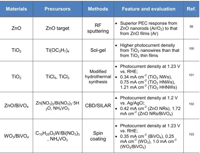
Nanostructured 1D metal oxides for photodetectors have been discussed by Zhai et al.88 1D nanostructures are regarded as ideal systems for investigating fundamental phenomena in nanoscale and studying aspect ratio dependence of properties of metal oxide materials for expected applications. In this comprehensive review article, photoresponse of 1D metal oxides including ZnO, SnO2, Cu2O, Ga2O3, Fe2O3, In2O3, CdO, and CeO2 are introduced and the sate- of-the-art of photodetector research is provided. There are other strategies to modify metal oxide materials for targeted applications, for instance, engineering of band structure, defects and crystallinity.89–91
1.4 Photoelectrochemical (PEC) water splitting 1.4.1 Mechanism and background
There is no doubt on critical necessity for development of environmentally friendly and sustainable energy even without mentioning numerical statistics on global energy crisis due to increased demand for energy.92 Therefore, producing alternative energies that can compete with fossil fuels has been of a great counterdemand. As hydrogen is suggested as a promising alternative energy source, PEC water splitting (also referred to photocatalytic water splitting) to dissociate water into hydrogen and oxygen by facilitating solar energy seems to be attractive.
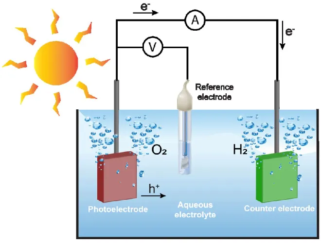
Figure 2 shows a graphical demonstration of a typical three-electrode PEC cell.
Fundamental background of PEC water splitting will be introduced by describing a typical PEC system consisting of anode and cathode. These electrodes are immersed in aqueous solution (weak acidic or alkaline solutions). For a practical use, pure water is not applicable due to very low ionic conductivity (>0.05 µS∙cm-1)91 that protons are not mobile enough to participate in redox reactions. (refer to Equation 1-3).
𝐻2O + 2ℎ+→ 2𝐻++1
2𝑂2 (𝑎𝑛𝑜𝑑𝑒) Equation 1 2𝐻++ 2𝑒−→ 𝐻2 (𝑐𝑎𝑡ℎ𝑜𝑑𝑒) Equation 2 𝐻2𝑂 + 2ℎ++ 2𝑒−→ 𝐻2+1
2𝑂2 Equation 3
A target material that can be either an anode or and cathode or both should exhibit