Research Collection
Conference Paper
Mobile Robot Miniaturization
A Tool for Investigation in Control Algorithms
Author(s):
Mondada, Francesco; Franzi, Edoardo; Ienne, Paolo Publication Date:
1993
Permanent Link:
https://doi.org/10.3929/ethz-a-010111554
Rights / License:
In Copyright - Non-Commercial Use Permitted
This page was generated automatically upon download from the ETH Zurich Research Collection. For more information please consult the Terms of use.
Experimental Robotics III, Proceedings of the 3rd International Symposium on Experimental Robotics, Kyoto, Japan, October 28-30, 1993, Springer Verlag, London, 1994, pp501-513.
Mobile robot miniaturisation:
A tool for investigation in control algorithms.
Francesco Mondada, Edoardo Franzi, and Paolo Ienne Swiss Federal Institute of Technology
Microcomputing Laboratory IN-F Ecublens, CH-1015 Lausanne E-mail: Francesco.Mondada@di.ep.ch
Edoardo.Franzi@di.ep.ch Paolo.Ienne@di.ep.ch
Abstract
The interaction of an autonomous mobile robot with the real world critically depends on the robots mor- phology and on its environment. Building a model of these aspects is extremely complex, making sim- ulation insucient for accurate validation of control algorithms.
If simulation environments are often very ecient, the tools for experimenting with real robots are often inadequate. The traditional programming languages and tools seldom provide enought support for real- time experiments, thus hindering the understanding of the control algorithms and making the experimen- tation complex and time-consuming.
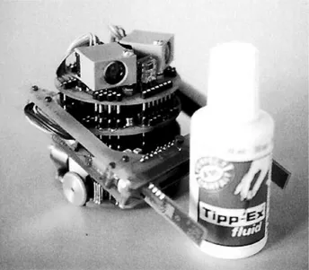
A miniature robot is presented: it has a cylindri- cal shape measuring 55 mm in diameter and 30 mm in height. Due to its small size, experiments can be performed quickly and cost-eectively in a small work- ing area. Small peripherals can be designed and con- nected to the basic module and can take advantage of a versatile communication scheme. A serial-link is provided to run control algorithms on a workstation during debugging, thereby giving the user the oppor- tunity of employing all available graphical tools. Once debugged, the algorithm can be downloaded to the robot and run on its own processor.
Experimentation with groups of robots is hardly possible with commercially available hardware. The size and the price of the described robot open the way to cost-eective investigations into collective be- haviour. This aspect of research drives the design of the robot described in this paper. Experiments with some twenty units are planned for the near future.
1. Introduction
Today the mobile robotics eld receives great atten- tion. There is a wide range of industrial applications of autonomous mobile robots, including robots for au- tomatic oor cleaning in buildings and factories, for mobile surveillance systems, for transporting parts in factories without the need for xed installations, and for fruit collection and harvesting. These mobile robot applications are beyond the reach of current technol- ogy and show the inadequacy of traditional design methodologies. Several new control approaches have been attempted to improve robot interaction with the real world aimed at the autonomous achievement of tasks. An example is the subsumption architecture proposed by Brooks [1] which supports parallel pro- cessing and is modular as well as robust. This ap- proach is one of the rst solutions systematically im- plemented on real robots with success. Other re- searchers propose new computational approaches like fuzzy logic [2] orarticial neural networks [3].
The interest in mobile robots is not only directed to- ward industrial applications. Several biologists, psy- chologist and ethologists are interested in using mo- bile robots to validate control structures observed in the biological world. Franceschini [4] uses a robot to validate the structure of the retina observed on a y, Beer [5] to replicate the mechanism that coordinates leg movements in walking insects, Deneubourg [6] to get a better understanding of collective behaviour in ant colonies.
All these research activities are based on mobile robot experimentation. A simpler way to validate con- trol algorithms is to use simulations, but the simpli- cations involved are too important for the results to
be conclusive. The control algorithm embedded in the robot must consider its morphology and the proper- ties of the environment in which it operates [7]. Real world features and anomalies are complex and di- cult to modelise, implying that the experimentation of control algorithms through simulation can only be used in preliminary study but cannot prove the suc- cess of the control algorithm in the real world. The sole way to validate an algorithm to deal with these problems is to test it on a real robot [8].
Many robots have been designed to perform experi- ments on control algorithms but only a few make cost- ecient experiments possible. Brooks has designed several robots with eective electronics and mechan- ics [9]. The control algorithms are programmed in the subsumption behavioural language, taking into ac- count software modularity, and real-time and parallel processing. Unfortunately, during experiments, only a few tools are available to improve the understanding of the control process. Moreover, the custom program- ming language makes code portability and algorithm diusion dicult. Steels [10] uses a video-camera to record robot actions during experiments but all the data concerning the robot control process are available only at the end of the experiment. Other platforms, such as the Nomad robot [11], make real-time inter- action possible via a radio link, and have standard programming languages, but the size of the robot and the environment it requires make experimentation un- comfortable.
The lack of a good experimentation mobile robot for single-robot experiments, means that it is im- possible today to perform collective-behaviour exper- iments. The programming environment and the real- time visualisation tools are totally insucient for this purpose.
The development of the miniature mobile robot Kheperaaddresses the problems mentioned above. Its hardware is designed so that it is small enough for the operation of several at the same time and in small ar- eas, for example on a desk-top. Modularity allows new sensors and actuators to be easily designed and added to the basic structure. A versatile software structure is provided to help the user to debug the algorithms and to visualise the results.
2. Hardware
Miniaturisation is an important challenge for indus- try: CD players, computers, video cameras, watches and other consumer products need to implementmany functionalities in a small volume. In the robotics eld many applications need small actuators, small teleop- erated machines or tiny autonomous robots. Dario
[12] gives a comprehensive description of the research eld and of the available technology. In the Khep- era design, miniaturisation is the key factor in making cost-eective experimentations possible both for single or multiple robot congurations.
2.1. Generalities
The robot presented in this paper is only a rst step in the direction of miniaturisation. Dario dene this category of robots as miniature robots. They mea- sure no more than a few cubic centimetres, generate forces comparable to those applied by human opera- tors and incorporate conventional miniature compo- nents. The next miniaturisation step needs special fabrication technologies, today in development. Khep- era uses electronic technology available today: the new family of 683xx microcontrollers from Motorola makes the design of complete 32 bit machines extremely com- pact. Surface mounted devices(SMD) allow an impor- tant increase in component density on printed circuit boards. New compact sensors, including some signal preprocessing on the sensing chip, reduce the need of additional circuitry. Only the mechanical parts (wheels, gears, manipulator) are built expressly for Khepera, as well as the magnetic sensors for count- ing the wheel revolutions.
The design of such miniaturised robots demands a great eort spanning several elds. The result is a complex compromise between functionalities to be implemented, available volume, current technology, power requirements, etc.
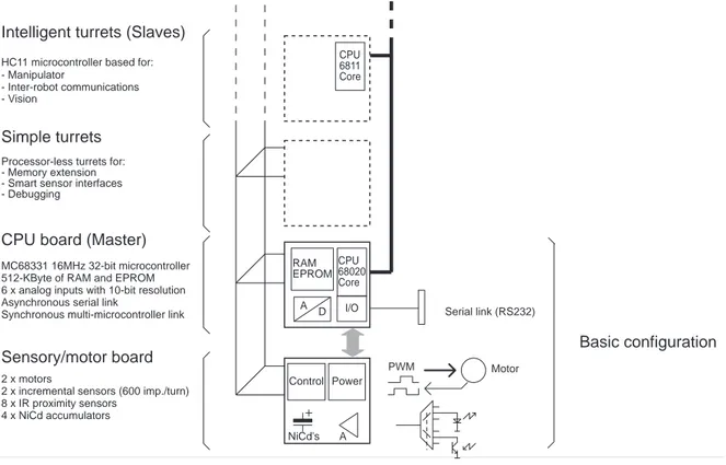
Khepera is composed of two main boards (gure 2).
pince.eps 8172 mm
Figure 1. The Khepera robot.
architecture.eps 155107 mm
Motor PWM
Multi-microcontroller extension network
MC68331 16MHz 32-bit microcontroller 512-KByte of RAM and EPROM 6 x analog inputs with 10-bit resolution Asynchronous serial link
A Control 2 x motors
2 x incremental sensors (600 imp./turn) 8 x IR proximity sensors
4 x NiCd accumulators
Synchronous multi-microcontroller link Serial link (RS232)
- Vision
Processor-less turrets for:
A D
RAM EPROM
NiCd's Power
Simple turrets
CPU board (Master)
Sensory/motor board
I/O - Manipulator
- Inter-robot communications
Intelligent turrets (Slaves)
CPU 68020 Core CPU 6811 Core HC11 microcontroller based for:
- Memory extension - Smart sensor interfaces - Debugging
Basic configuration
Parallel main processor bus
Figure 2. Khepera hardware architecture.
topology.eps 5852 mm
Master 68331
Basic configuration of Khepera
Slave HC11 Communication
Slave HC11 Manipulator Slave
HC11 Vision
Slave HC11 Other
Figure 3. Khepera communication network topology.
Application-specic extension turrets for vision, for inter-robot communications, or which are equipped with manipulators can be directly controlled via the Khepera extension busses. Khepera can be powered by an external supply when connected for a long time to a visualisation software tool; however, on-board ac-
cumulators provide Khepera with thirty minutes of autonomous power supply.
2.2. Distributed processing
One of the most interesting features of Khepera is the possibility of connecting extensions on two dierent busses. One parallel bus is available to connect sim- ple experimentation turrets. An alternative and more sophisticated interface scheme implements a small lo- cal communication network; this allows the connec- tion of intelligent turrets (equipped with a local micro- controller) and the migration of conventional or neu- ral pre-processing software layers closer to the sensors and actuators. This communicationnetwork (gure 3) uses a star topology; the main microcontroller of the robot acts as a master (at the centre of the star). All the intelligent turrets are considered as slaves (on the periphery of the star) and use the communication net- work only when requested by the master.
This topology makes it possible to implement dis- tributed biological controls, such as arm movement coordination or feature extraction and pre-processing in the vision, as observed in a large number of insects.
The multi-microcontroller approach allows the main
microcontroller of Khepera to execute only high level algorithms; therefore attaining a simpler programming paradigm.
2.3. Basic conguration
The new generation of Motorola microcontrollers and in particular the MC68331 makes it possible to build very powerful systems suitable for miniature neural control. Khepera takes advantage of all the micro- controller features to manage its vital functionality.
The basic conguration of Khepera is composed of the CPU and of the sensory/motor boards.
The CPU board is a complete 32 bit machine in- cluding a 16 MHz microcontroller, system and user memory, analogue inputs, extension busses and a se- rial link allowing a connection to dierent host ma- chines (terminals, visualisation software tools, etc.).
The microcontroller includes all the features needed for easy interfacing with memories, with I/O ports and with external interruptions. Moreover, the large number of timers and their ability to work in associ- ation with the I/O ports indicate that this device is the most important component in the design.
The sensory/motor board includes two DC mo- tors coupled with incremental sensors, eight analogue infra-red (IR) proximity sensors and on-board power supply. Each motor is powered by a 20 kHz pulse width modulation (PWM) signal coming from a ded- icated unit of the microcontroller. These signals are boosted by complete four-quadrant NMOS H bridges.
Incremental sensors are realised with magnetic sen- sors and provide quadrature signals with a resolution of 600 impulsions per wheel revolution. IR sensors are composed of an emitter and of an independent receiver. The dedicated electronic interface is built with multiplexers, sample/hold's and operational am- pliers. This allows the measurement of the absolute ambient light and the estimation, by reection, of the relative position of an object from the robot.
2.4. Additional turrets
To make experiments involving environment recog- nition, object detection, object capture and object recognition possible, two intelligent turrets have been designed and built: one for stereoscopic vision, the other containing a manipulator.
The stereoscopic vision turret employs two 64 pixel linear photoelement arrays and a dedicated optical el- ement. The analogue value of each pixel is coded on 16 grey levels. To obtain useable data under a wide spectrum of enlightenment conditions, an additional sensor is used to perform as an automatic iris: the in- tegration time necessary for the photoelement arrays
piggy-back.eps 75138 mm
10 mm Sensory/motor CPU
Vision
Bus
Figure 4. Khepera physical structure: Basic sen- sory/motor, CPU and vision boards.
is controlled by intensity of the ambient light. Mon- dadaet al. [8] proved the validity of this stereoscopic vision in robot navigation (spatial frequency ltering was used in obstacle detection and avoidance).
The manipulator turret makes Khepera capable of an interaction with objects of its environment. Two DC motors control the movements of the manipulator (elevation and gripping). Dierent classes of objects can be detected by the gripper sensors which measure sizes and resistivities.
Robots displaying collective behaviour need means to perform inter-robot communications and localisa- tion. Turrets providing Khepera with these function- alities are under study at the time of writing.
software.eps 71131 mm
Mail box
External interruption
Stand-alone process Motion control IR control
Protocol with a visualisation software tool Turret
communications
Main board
High level main Application
High level turret control
Communication network
Gripper board
To the other turrets
Gripper control
Arm control
Object control
Hardware link
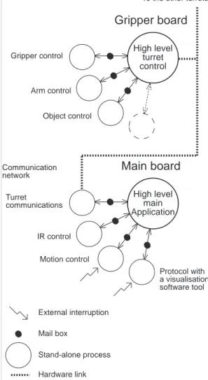
Figure 5. Hierarchical software structure.
3. Software
Managing all the Khepera resources is a complex task.
The large number of asynchronous events to control, and the necessity to share some critical interfaces led to the development of a complete low-level software organised as a collection of basic I/O primitives [13].
3.1. Hierarchical software structure
The multi-microcontroller approach and the complex tasks to manage required a hierarchical approach to the software structure. The concept chosen applies when intelligent turrets (equipped with a microcon- troller) are used. Two software structures are imple- mented: a single high-level application program and a number of stand-alone local processes (gure 5).
Stand-alone local processes (e.g., for IR sensor se- quencing, motion control, wheel incremental-sensor
counting, etc.) are executed cyclically according to their own event timer and possibly in association with external interruptions. The high-level applica- tion software run the control algorithm and commu- nicate with the stand-alone local processes via a mail- box mechanism. This decoupling of low- and high- level tasks makes the development of complex appli- cations quick and easy.
3.2. Control of Khepera
Experiments with Khepera are performed in two dif- ferent ways: by running algorithms on autonomous robots or in connection with visualisation software tools.
As already mentioned, the details of the basic in- put/output activities are managed through a library of stand-alone processes. During the development, the standard RS232 link is used, through a generic high level protocol, to communicate with these pro- cesses from a workstation. The application software is therefore run on the workstation and calls to the basic primitives make it possible to monitor the robot activity possible. All standard and specialised visual- isation tools can be employed to simplify the control algorithm debugging.
Because the application software is written in stan- dard C language, debugged algorithms can easily be converted to run on the Khepera CPU. Applications can be downloaded to Khepera and the robot becomes autonomous from the development environment.
4. Experimentation environment
The quality of the measurements obtained in robot experiments and the eciency of the whole experi- mentation process critically depends on the structure of the working environment. Tools currently available for simulation are far better developed than those used for experimenting with real robots. The real time in- teraction with the control process and the continuous visualisation of the parameters make possible a faster and better understanding of the mechanisms involved.
For these reasons, it is necessary to develop better vi- sualisation and interactive software tools adapted to the experimentation tasks.
The simplest way to implement a comprehensive graphical interface is to use a scientic workstation.
This must be connected to the robot to collect the data for display and to communicate the orders com- ing from the user. The physical arrangement of all ele- ments involved in the experiment must be compact, al- lowing a complete and comfortable control. Thanks to miniaturisation, this can be obtained as illustrated in gure 6: the entire conguration, including robot, en-
environment.eps 7656 mm
Figure 6. Khepera experimentation environment.
vironment and workstation, is conveniently arranged on a normal table. In the arrangement shown in g- ure 6 the serial link cable does not disturb the move- ment of the robot. A device to prevent the cable from rolling up is placed at mid-length on the serial cable.
For experiments involving more than one robot, the wired serial link can no longer be used. Special radio communication modules are being developed for this purpose. This additional module will provide means to control several Khepera at the same time.
With a wired or a radio serial link, the data ow be- tween workstation and robot must be as little as pos- sible. To minimise this ow without restricting user ability, the control algorithm runs on the workstation and communicates to the robot only the data concern- ing sensors and motors. This conguration is optimal when an important number of parameters must be dis- played and controlled.
Several programming and visualisation tools are used to perform experiments with Khepera. Here, three programming styles will be presented: the rst uses a classical programming language to build stand- alone applications, the second a complete graphical programming interface and the third is a compromise between the previous two, making the best of both.
4.1. Complete applications
A rst programming possibility is to code the con- trol algorithm and the user interface in a traditional way. This is a good choice for software engineers or re- searchers who have already developed a visualisation and control interface, for instance in a simulation en- vironment. It is often the case that, when a researcher starts to perform real robot experiments, a simulator has already been developed and used for preliminary
studies. In this situations, the simulator can easily be adapted by replacing the simulated actions with calls to the interface with the real robot. This can usually be made without modifying the user interface.
Some very interesting results have been achieved with this approach on the neural networks simulator developed by Ph. Gaussier [14]. The simulator is used as a tool to design neural networks for robot control.
A real time visualisation interface permits a veriable step-by-step learning process on the robot.
A similar experience in interfacing Khepera with a simulator is in progress using the simulator BugWorld, developed at the Institute fur Informatik of the Uni- versity of Zurich. In this case, the control interface will be complemented with a measurement system which enables the user to plot the trajectory of the robot in real time on the host screen.
4.2. LabVIEW
The software packageLabVIEW is a commercialprod- uct from National Instruments [15] and runs on several host machines (PC, Macintosh or Sun workstations).
LabVIEW has been developed as an environment for the design ofvirtual instruments (VI). Every VI com- prises a control panel and an interconnection diagram.
On the panel, the user can interactively specify graph- ical devices for input (e.g., sliding cursors, buttons, text controls) and for output (e.g., gauges, images, graphs). In the diagram, the user graphically enters the functionality of the VI. A library of standard func- tionalities is available to perform this task: icons per- forming numerical functions, string treatment, matrix computations, etc. can be linked together to design an algorithm. An icon can be associated with a complete VI and used hierarchically in the diagram of another instrument, thus allowing a modular approach. More- over, modules can be written in standard program- ming languages, such asCorPascal.
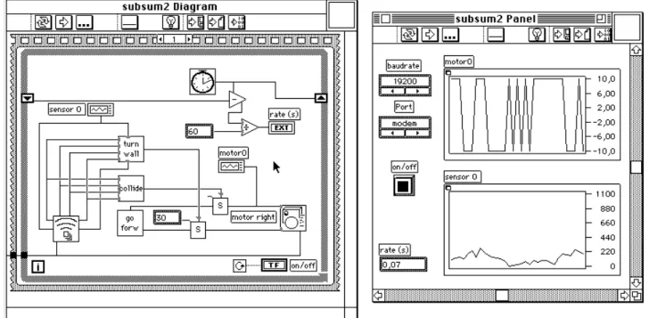
An sample experiment is shown in gure 7. The diagramrepresents the computationof a subsumption- based algorithm [1]. Two modules, collide and turn wall, take inputs from the sensors (bottom left icon) and are connected to feed appropriate commands to the motors (right icon). The sensorsand motoricons communicate with the robot through the wired serial link. The two graphs on the panel visualise the state of one motor and of one sensor. The modules in the top right part of the diagram evaluate the period required to recompute the algorithm; this is displayed at the bottom left of the panel.
LabVIEW is an optimal tool for the design of ex- perimentation environments without the use of pro- gramming languages. The complete graphical inter-
labview.eps 16985 mm
Figure 7. LabVIEW display.
face helps specifying the interaction items of the panel but becomes inecient when designing complex con- trol algorithms. In this case, it is more ecient to de- sign modules using standard programming languages.
The only disadvantage of LabVIEW version 2 is that the display possibilities are somehow limited. The ver- sion 3 will provide more interactive capabilities and will be a better design tool for mobile robot experi- mentation.
4.3. Grapher
Grapher [16] is an experimentation tool developed at LAMI by Y. Cheneval and L. Tettoni for the Es- prit Elena Project. Due to code optimisation and to improve performance, the software package is avail- able only on SUN SparcStations. In the Grapher en- vironment, an experiment is dened interconnecting modules that perform sub-tasks such as pure compu- tation, visualisation or control. The programming of these modules is done in C language. The intercon- nections are graphically specied by the user. The wiring diagram is on a single level, therefore prevent- ing a hierarchical approach. For this reason, and to avoid over-complicated wiring schemes, the modules perform quite complex tasks. To facilitate the de- velopment, a large number of standard modules are available, making the best of the available hardware possibilities; the performance and exibility of the vi-
sualisation is particularly impressive. Comparing Gra- pher to LabVIEW, the former is less intuitive, needs some programming knowledge but make complex ex- perimentation ecient. The experiment described in the next section illustrates this aspect.
5. Experimentation in Distributed Adaptive Control
As an example of the development techniques out- lined above, the environment to evaluate a control ar- chitecture will be presented in this section. The con- trol mechanism is developed according to the design methodology ofdistributed adaptive control [17]. This approach is in turn derived from a distributed self- organising model of the behavioural phenomenon of classical conditioning [18] [19]. The example involves an autonomous agent that can learn to avoid obstacles using collision and proximity sensors.
The control structure consists of a neural net with three groups of neurons (gure 9) named Uncondi- tioned Stimulus (US),Conditioned Stimulus(CS) and Motor actions (M). Neurons of the US group are di- rectly connected with collision sensors, simulated here by the saturation of the proximity sensors. A prewired connection between the US and the M groups imple- ments the robot basic reex of avoiding obstacles at the time of a collision. Neurons of the CS group obtain their inputs from the proximity sensors. The learning
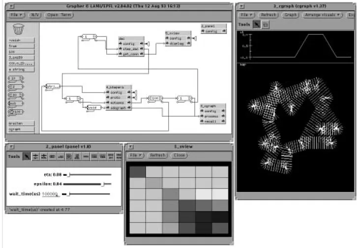
grapher.eps 170119 mm
Figure 8. Grapher display.
is performed with an Hebbian rule on the connections between CS and US. The weights Ki;j of these con- nections are updated according to:
Ki;j= 1
N
(sisj,sKi;j) (1) where N denes the number of units in the CS, is the learning rate, the decay rate, and sthe average activation in the group US.
This way, the robot can develop a conditional re- sponse, learning to avoid obstacles using the proxim- ity sensors without producing collisions. During the experimentation it is interesting to observe the evolu- tion of the learning process on the matrixK, which depends on and.
The software environment used for this experiment is Grapher (see section 4.3). Figure 8 shows the ex- periment display on a SUN SparcStation. The princi- pal window, on the top left, illustrates the functional diagram of the experiment: The dac module (centre top) performs the computation of the algorithm and
interacts with the modulekhepera(centre bottom) to control the robot. Three other modules permit user interface. The panel module (top right) allows the user to control , and the algorithm computation period by means of sliding cursors. Thexviewmodule displays the K matrix in the centre bottom window.
Finally, thecgraphmodule (bottom right) displays the sensor state and the trajectory of the robot, as visible in the rightmost window.
If the control algorithmCsource with no display ca- pabilities is available, the experimental set-up can be designed in less than one day. The user gains com- plete control of the physical robot, the development environment and all the parameters of the algorithm in real time, thus obtaining an optimal visualisation of the process.
6. Conclusions
The miniaturisation of Khepera makes a compact and ecient experimentation environment possible. As- sociated with eective software tools, this robot is an
dac.eps 7972 mm
Conditioned Stimulus Hebbian rule
Unconditioned Stimulus
prewired reflexes avoid right avoid left go forward (default) collision detectors
proximity sensors
Motor actions
CS
US
Figure 9. Distributed Adaptive Control experiment architecture.
optimalplatform to test control algorithms. The mod- ularity at the hardware, software and control tools lev- els gives to the user the necessary exibility to perform accurate experiments quickly. An example of exper- imentation environment has been presented. The re- duced size and cost of the miniature robots described make possible experimentation on collective behaviour among groups of robots. This will be the main re- search activity in the near future.
Acknowledgements
The authors would like to thank Andre Guignard for the important work in the design of Khepera and Jelena Godjevac, Paul Verschure, Claude Touzet, Philippe Gaussier, Stephane Zrehen, Yves Cheneval and Laurent Tettoni for help in testing the algorithms and in the development of the experimentation tools.
This work has been supported by the Swiss National Research Foundation (project PNR23).
References
[1] R. A. Brooks. A robust layered control system for a mobile robot. IEEE Robotics and Automation, RA- 2:14{23, March 1986.
[2] J. Heller. Kollisionsvermeidung mit fuzzy-logic.Elek- tronik, 3:89{91, 1992.
[3] U. Nehmzov and T. Smithers. Using motor actions for location recognition. In F. J. Varela and P. Bourgine, editors,Proceedings of the First European Conference on Articial Life, pages 96{104, Paris, 1991. MIT Press.
[4] N. Franceschini, J.-M. Pichon, and C. Blanes. Real time visuomotor control: From ies to robots. In Proceedings of the Fifth International Conference on Advanced Robotics, pages 91{95, Pisa, June 1991.
[5] R. D. Beer, H. J. Chiel, R. D. Quinn, K. S. Espen- schied, and P. Larsson. A distributed neural network architecture for hexapod robot locomotion. Neural Computation, 4:356{65, 1992.
[6] J. C. Deneubourg, S. Goss, N. Franks, A. Sendova, A. Franks, C. Detrin, and L. Chatier. The dynam- ics of collective sorting: Robot-like ant and ant-like robot. In J. A. Mayer and S. W. Wilson, editors, Simulation of Adaptive Behavior: From Animals to Animats, pages 356{365. MIT Press, 1991.
[7] R. A. Brooks. Intelligence without representation.
Articial Intelligence, 47:139{59, 1991.
[8] F. Mondada and P. F. M. J. Verschure. Modeling system-environment interaction: The complementary roles of simulations and real world artifacts. InPro- ceedings of the Second European Conference on Arti- cial Life, Brussels, 1993.
[9] R. A. Brooks. Elephants don't play chess. Robotics and Autonomous Systems, 6:3{15, 1990. Special issue.
[10] L. Steels. Building agents out of autonomous behav- ior systems. InThe Biology and Technology of Intel- ligent Autonomous Agents. NATO Advanced Study Institute, Trento, 1993. Lecture Notes.
[11] Nomadic Technologies, Inc., Palo Alto, Calif. The NOMAD Robot. Data-sheet.
[12] P. Dario, R. Valleggi, M. C. Carrozza, M. C. Mon- tesi, and M. Cocco. Microactuators for microrobots:
A critical survey.Journal of Micromechanics and Mi- croengineering, 2:141{57, 1992.
[13] E. Franzi. Low level BIOS of minirobot Khepera. In- ternal report R93.28, LAMI - EPFL, Lausanne, 1993.
[14] P. Gaussier. Simulation d'un systeme visuel com- prenant plusieurs aires corticales: Application a l'- analyse de scenes. PhD thesis, Paris XI - Orsay, Paris, November 1992.
[15] National Instruments Corporation.LabVIEW 2, Jan- uary 1990. User Manual.
[16] Y. Cheneval, P. Bovey, and P. Demartines. Task B2:
Unied Graphic Environment. Delivrable R1-B2-P, ESPRIT Elena Basic Research Project no. 6891, June 1993.
[17] P. F. M. J. Verschure, B. J. A. Koese, and R. Pfeifer.
Distributed adaptive control: The self-organization of structured behavior. Robotics and Autonomous Agents, 9:181{96, 1992.
[18] P. F. M. J. Verschure and A. C. C. Coolen. Adap- tive elds: Distributed representations of classically conditioned associations. Network, 2:189{206, 1991.
[19] I. P. Pavlov.Conditioned Reexes. Oxford University Press, London, 1927.