ZUR WIRTSCHAFTSINFORMATIK UND ANGEWANDTEN INFORMATIK ISSN 0937-3349
Nr. 65
Modelling and Validating Business Collaborations:
A Case Study on RosettaNet
Andreas Sch¨ onberger
March 2006
FAKULT¨ AT WIRTSCHAFTSINFORMATIK UND ANGEWANDTE INFORMATIK
OTTO-FRIEDRICH-UNIVERSIT¨ AT BAMBERG
Distributed and Mobile Systems Group
Otto-Friedrich Universit¨at Bamberg
Feldkirchenstr. 21, 96052 Bamberg, GERMANY
Prof. Dr. rer. nat. Guido Wirtz
http://www.uni-bamberg.de/en/fakultaeten/wiai/faecher/informatik/lspi/
Due to hardware developments, strong application needs and the overwhelming influence of the net in almost all areas, distributed and mobile systems, especially software systems, have become one of the most important topics for nowadays software industry. Unfortunately, distri- bution adds its share to the problems of developing complex software systems. Heterogeneity in both, hardware and software, concurrency, distribution of components and the need for inter- operability between different systems complicate matters. Moreover, new technical aspects like resource management, load balancing and deadlock handling put an additional burden onto the developer. Although subject to permanent changes, distributed systems have high requirements w.r.t. dependability, robustness and performance.
The long-term common goal of our research efforts is the development, implementation and evaluation of methods helpful for the development of robust and easy-to-use software for com- plex systems in general while putting a focus on the problems and issues regarding the software development for distributed as well as mobile systems on all levels. Our current research acti- vities are focussed on different aspects centered around that theme:
• Robust and adaptive Service-oriented Architectures: Development of design methods, lan- guages and middleware to ease the development of SOAs with an emphasis on provable correct systems that allow for early design-evaluation due to rigorous development me- thods and tools. Additionally, we work on approaches to autonomic components and container-support for such components in order to ensure robustness also at runtime.
• Agent and Multi-Agent (MAS) Technology: Development of new approaches to use Multi- Agent-Systems and negotiation techniques, for designing, organizing and optimizing com- plex distributed systems, esp. service-based architectures.
• Peer-to-Peer Systems: Development of algorithms, techniques and middleware suitable for building applications based on unstructured as well as structured P2P systems. A specific focus is put on privacy as well as anonymity issues.
• Context-Models and Context-Support for small mobile devices: Investigation of techni- ques for providing, representing and exchanging context information in networks of small mobile devices like, e.g. PDAs or smart phones. The focus is on the development of a tru- ly distributed context model taking care of information reliability as well as privacy issues.
• Visual Programming- and Design-Languages: The goal of this long-term effort is the uti- litization of visual metaphores and languages as well as visualization techniques to make design- and programming languages more understandable and, hence, easy-to-use.
More information about our work, i.e., projects, papers and software, is available at our ho- mepage. If you have any questions or suggestions regarding this report or our work in general, don’t hesitate to contact me at guido.wirtz@wiai.uni-bamberg.de
Guido Wirtz
Bamberg, April 2006
A Case Study on RosettaNet
Andreas Sch¨ onberger
Lehrstuhl f¨ ur Praktische Informatik, Fakult¨ at WIAI
Abstract The way business processes are organised heavily influences the flexibility and the expenses of enterprises. The capability to address changing market needs in a timely manner and to provide appropriate pricing is indispensable in a world of internationalisation and gro- wing competition. Optimising processes that cross enterprise boundaries potentially is a key success factor in achieving this goal but it requires the information systems of the participa- ting enterprises to be consistently integrated. This gives rise to some challenging tasks. The personnel involved in building up business collaborations comes from different enterprises with different business vocabulary and background which requires extensive communication support.
The lack of central technical infrastructure, typically prohibited by business politics, calls for a truly distributed and computer-aided collaboration structure, so that the resulting complexity must be handled somehow. Nevertheless robustness is an important factor in building business collaborations as these may exchange goods of considerable value.
This technical report proposes the use of a two step modelling approach that separates business logic, modelled in the so-called centralised perspective (CP), from its distributed implementati- on, modelled in the so-called distributed perspective (DP). The separation of these perspectives enables business people to concentrate on business issues and to solve communication problems in the CP whereas technical staff can concentrate on distribution issues. The use of stringent modelling rules is advised in order to provide the basis for formal analysis techniques as one means to achieve robustness.
Considering the choreography of RosettaNet Partner Interface Processes (PIPs) as the sub- ject of analysis, UML activity diagrams for modelling the CP and WSBPEL for modelling the DP are described as enabling techniques for implementing the proposed two step modelling approach. Further, model checking is applied to validate the CP and DP models in order to detect errors in early design phases. As the adequacy of model checking tools highly depends on the detailed modelling techniques as well as the properties to be checked, a major part of our discussion covers relevant properties and requirements for a model checker.
Keywords validation, verification, UML, business process modelling, distributed system,
business to business integration, distributed consensus, RosettaNet, WSBPEL
Contents
1 Introduction 1
2 Basics 4
2.1 Model Checking . . . . 4
2.2 RosettaNet . . . . 6
3 An approach for modelling business collaborations 8 3.1 The core approach . . . . 8
3.1.1 The centralised perspective . . . . 8
3.1.2 The distributed perspective . . . . 12
3.2 Using UML activity diagrams for modelling the centralised perspective . . . . . 18
3.3 Using WSBPEL for modelling the distributed perspective . . . . 20
4 A RosettaNet use case 23 4.1 The centralised perspective . . . . 25
4.2 The distributed perspective . . . . 29
4.2.1 Conceptual modelling . . . . 29
4.2.2 WSBPEL realisation . . . . 38
5 Validating business collaborations 47 5.1 Collaboration properties that should be checked . . . . 47
5.1.1 Sanity of the centralised perspective . . . . 48
5.1.2 Conformance of the distributed implementation to the centralised per- spective . . . . 49
5.1.3 Interference of local business politics with the centralised perspective . . 52
5.2 Requirements of a model checker . . . . 52
5.3 Validating the use case . . . . 53
5.3.1 Validating the centralised perspective . . . . 54
6 Related work 73
7 Conclusion, practical experience and future work 78
Bibliography 80
A Promela validation models 82
B List of previous University of Bamberg reports 111
List of Figures
1 Abstraction of system S to S’ . . . . 5
2 UML activity diagram visualising the BOV of a PIP . . . . 6
3 Idealised run of 2PC protocol . . . . 10
4 Coordinator automaton of MCP . . . . 15
5 Participant automaton of MCP . . . . 16
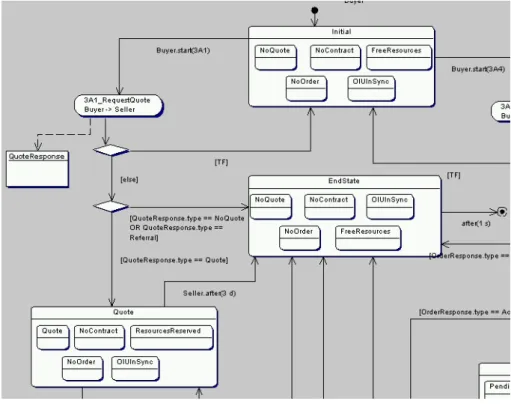
6 Use case: Path from state Initial to state Quote . . . . 25
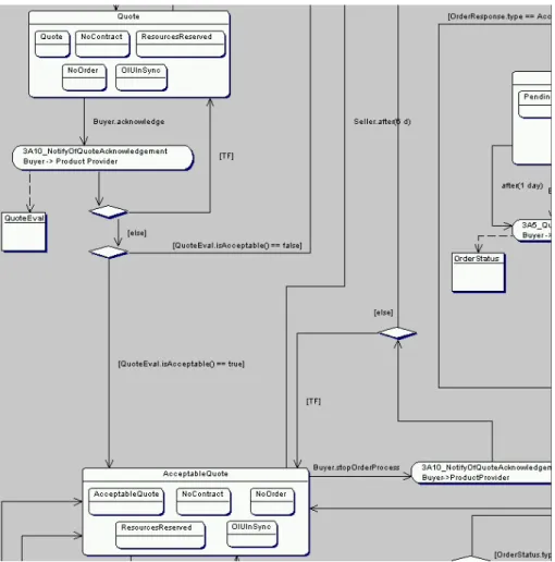
7 Use case: Path from state Quote to state AcceptableQuote . . . . 27
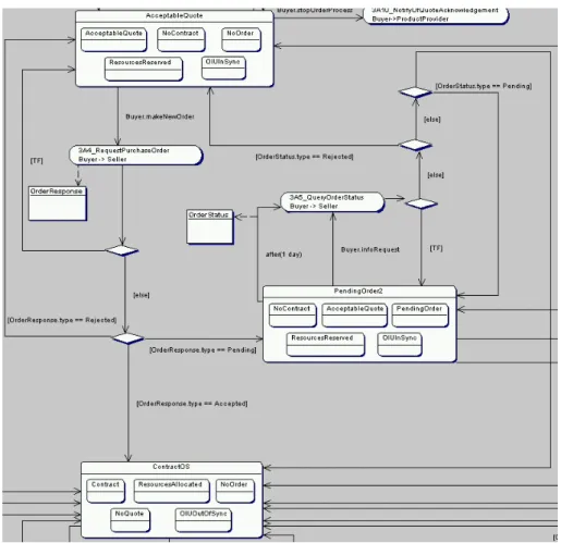
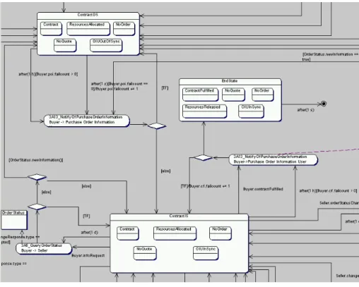
8 Use case: Path from state AcceptableQuote to state ContractOS . . . . 28
9 Use case: Path from state ContractOS to state EndState . . . . 29
10 Sender automaton of a Two-Action Activity . . . . 30
11 Receiver automaton of a Two-Action Activity . . . . 31
12 Sender automaton of a Single-Action Activity . . . . 33
13 Receiver automaton of a Single-Action Activity . . . . 34
14 Message exchange between protocol process and internal process . . . . 35
15 Separate variables for each guard . . . . 56
16 Reuse of variables in guards . . . . 57
17 A loop through PIP 3A7 14 . . . . 58
18 Receiver automaton actually validated . . . . 67
19 Sender automaton actually validated . . . . 68
1 Media Control Protocol validation levels . . . . 50
2 PIP execution protocol validation levels . . . . 51
List of Abbreviations
2PC Two-Phase-Commit Protocol BOV Business Operational View CP Centralised Perspective CTL Computation Tree Logic DP Distributed Perspective FSV Functional Service View
IFV Implementation Framework View MC Micro-choreography
MCP Media Control Protocol OIU Order Information User PIP Partner Interface Process PIPXP PIP Execution Protocol
PLTL Propositional Linear Time Logic RTC Real Time Clock
UML Unified Modeling Language
WSBPEL Web Services Business Process Execution Language
1 Introduction
Business processes define how enterprises produce and exchange goods and services. The flow of information is the main leverage for controlling business processes and heavily influences the flexibility and the expenses of enterprises. One example for being flexible is giving the customer the possibility to configure the product himself, e.g. choosing the colour of product parts or choosing add-ons that provide more functionality. But this requires enterprises to quickly inte- grate customer preferences in the current production schedule, i.e. the flow of information must be well-designed and well-managed. One example for reducing costs is minimising the time un- til goods and services are billed which again requires a well-designed and well-managed flow of information. Enterprises can use flexibility and minimal expenses to realise strategies like providing a high customer value or offering the best price. Hence, optimising business processes is a core technique for enterprises to continue to exist in stiff competition. Optimising business processes can be done by automating the flow of information. Automating the flow of infor- mation of business collaborations between enterprises, i.e. optimising cross-enterprise business processes, still has unexploited potential to furnish competitive advantages but gives rise to hard challenges as well.
The personnel involved in building up business collaborations frequently comes from different enterprises with different business vocabulary and background which requires extensive commu- nication support. The lack of central technical infrastructure, typically prohibited by business politics, demands for truly distributed computation so that the resulting complexity must be handled somehow. Nevertheless, robustness is an important factor in building business collabo- rations as these may exchange goods of considerable value. Therefore we propose the following approach to building up business collaborations:
1. Modelling a business collaboration from a centralised perspective. Communi- cation between personnel from different enterprises can be supported by first focussing on the business logic of the collaboration. The so-called centralised perspective (CP) specifies the abstract business state of the collaboration, the events that trigger state changes, so- called micro-choreographies that consistently perform state changes and the control flow of the collaboration. Interpreting the CP as the common view of all collaboration partici- pants on the collaboration progress is key to understanding the CP. Thus the state under consideration reduces to the facts the collaboration participants have to agree upon and micro-choreographies can be interpreted as single actions that change state leaving out message passing details. This modelling metaphor makes modelling quite simple and does not require technical experts, who possibly don’t know business logic very well, to create the model. Nevertheless, the modelling technique applied should have clear semantics to avoid misunderstandings between collaboration participants and to provide the founda- tion of (semi-)automated generation of a distributed implementation. The model of the CP then gives context to a distributed implementation of the collaboration which is a similar approach as pursued by WS-CAF/WS-Context ([OAS03]).
2. Modelling a business collaboration from a distributed perspective. The so-
called distributed perspective (DP) models the implementation of the CP in a distributed
environment by specifying a representation of the abstract business state and by spec-
ifying protocols for performing micro-choreographies that ensure distributed consensus.
2 1 INTRODUCTION Complexity is handled in a twofold way. First, the global view on business logic is already fixed when modelling the DP, so technical aspects can be focussed. Second, the concept of micro-choreography helps in unitising the implementation model, which decomposes the overall task. Further, tasks to be fulfilled on the DP are achieving agreement on the start of micro-choreographies, proving that the DP conforms to the CP and integrating local business politics of the collaboration participants.
3. Applying model checking techniques to ensure robustness. Business collabora- tions possibly exchange goods and services of considerable value. Therefore, a robust design is needed in order to avoid losses. This means that the protocol to perform a collaboration should ideally be defined in such a way that errors are only possible by violating the protocol thus identifying a responsible person to call to account for losses in case an error occurs. This goal requires to look at all possible protocol runs for a given environment. As the set of possible runs in a concurrent environment grows quickly, time- consuming and error-prone manual analysis should be extended by automated analysis techniques such as model checking. Model checkers compute all possible runs of a given protocol and offer the possibility to check properties. Model checking is suited to per- form validation in early design phases because models are relatively small and undetected errors cause high costs. Major problems in applying model checking techniques are the identification of relevant properties to check and the choice of the right model checker.
Therefore this technical report gives a taxonomy of relevant properties of business collab- orations and identifies requirements for model checkers. A core requirement for applying model checking is that the model checker in use can be applied directly to the models of the CP and DP or, at least, to enhanced models of the CP and DP because having to model the collaboration twice would be too costly.
In practice, the approach proposed must be supported by suitable technologies and tools. As the relationships between enterprises are numerous, i.e. enterprises have many partners, and dynamic, i.e. enterprises acquire and lose partners, these technologies and tools should be based on standards. Standards support quick and low-cost automation of business collaborations.
We propose UML activity diagrams ([OMG03]) and WSBPEL ([IBM03]) as enabling, but not exclusive, technologies for modelling the CP and the DP respectively. UML activity diagrams offer a visual notation which supports the communication functionality of the CP. WSBPEL and in particular Web Services are platform and programming language independent which is important for connecting heterogeneous systems. Both, UML activity diagrams and WSBPEL, rely on standards.
A case study on choreographing RosettaNet Partner Interface Processes (PIPs) is conducted to evaluate the approach proposed in conjunction with UML activity diagrams and WSBPEL.
RosettaNet suits well as the subject of our case study because it is a standard itself and a major part of the RosettaNet standard is devoted to standardising message contents of business collaborations, an important task that is not addressed by our approach. The use of model checkers, namely TCM/TATD
1for validating the CP and SPIN
2for validating parts of the DP, is shown by applying them to the models of the case study. The use of these tools is not shown in a general way because model checking depends on the detailed modelling techniques
1
http://wwwhome.cs.utwente.nl/~tcm/tatd.html
2
http://spinroot.com/spin/whatispin.html
as well as the properties to be checked. A more important result of our work is therefore the creation of a taxonomy of relevant properties for business collaborations and the identification of requirements for a model checker.
This technical report is structured as follows. Section 2 gives a short introduction to the technologies applied. Section 3 explains our modelling approach in detail and shows how UML activity diagrams and WSBPEL can be used for modelling the two complementary perspectives.
Section 4 introduces the use case of the case study and describes the modelling of the use case in detail. In section 5 the modelling results are validated and a taxonomy of properties as well as core requirements for a model checker are given. Section 6 then discusses related work.
Finally, section 7 concludes the paper and identifies future work.
4 2 BASICS
2 Basics
The technologies and concepts used in this report range from modelling systems in general, UML 1.5 activity diagrams ([OMG03]), Web Services
3and WSBPEL ([IBM03]) to model checking as well as RosettaNet
4. A comprehensive introduction to all of these is out of scope of this report.
Therefore, only a short introduction to model checking and RosettaNet is provided here.
2.1 Model Checking
Model checking is a technique for validating finite systems. Finiteness is a requirement because, in general, the whole state space is being explored for validation purposes. Usually, temporal logic is used to formulate properties that are then proved to be true or not. Temporal logic is particularly useful to express relationships between multiple states of the state space under consideration. The atoms of temporal logic formulae refer to single states of a state space so that, normally, their formalisation depends on the type of system to be validated.
A model checker is a tool for applying model checking techniques to particular types of systems.
Model checkers differ in input language for specification of systems, in query language for for- malisation of properties and in algorithms for verifying properties. The main functionality of a model checker is the application of verification algorithms as well as the translation of input specifications and properties into a structure suitable for verification. Input and query language are crucial for intuitive use of a model checker. Frequently, a system must be translated to the input language of a model checker before it can be validated, so intuitive use is important.
Ideally, the paradigm of the input language fits the system under consideration. For example, the widely-used model checker SPIN uses the paradigm of concurrent processes that exchange messages via message channels.
Model checkers are frequently used for validating concurrent systems. As the components of a concurrent system are asynchronously executed, the state space of such systems usually in- creases exponentially in the number of components and states of components. This necessitates the use of automated methods for analysis. Unfortunately, the validation of systems often fails because available validation resources, in terms of CPU cycles and main memory, do not suf- fice for the huge state space of concurrent systems. This problem is also known as the state explosion problem. If the state space of a system is too huge or not finite then abstraction mechanisms can be applied.
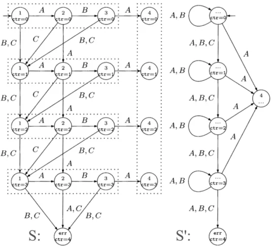
To do so, a system S is translated into an abstract system S’ that typically has a smaller state space. Then S’ is validated instead of S and the validation results are transferred to S. Figure 1 shows an abstraction example (taken from [BBF01], p.111). The number of states in the left system have been reduced by collapsing the states in a dotted area to one state respectively.
The transitions of S have been transferred to S’ according to the following rule: If a transition starts from/ends in a state in S than it starts from/ends in its corresponding collapsed state in S’. The result of this abstraction is shown on the right side of the figure. S’ has a smaller state space than S but it allows for more system runs. Apparently, not all properties that hold for S’ also hold for S. For example, it can be shown that, only using A transitions, every state in
3
http://www.w3.org/2002/ws/
4
http://www.rosettanet.org/
Figure 1: Abstraction of system S to S’
S’ is reachable. This property does not hold for S.
In order to decide whether a property can safely be transferred or not, the distinction between safety properties and liveness properties is useful.
Informally speaking, a safety property expresses that a particular state will never be reached whereas a liveness property expresses that a particular state will be reached if some conditions are met. The classification is easier to make following the rule in [BBF01], p.84, for identifying safety properties:
[...]when a safety property is violated, it should be possible to instantly notice it. If this depends on the remainder of the behaviour, then a behaviour which would end immediately would not violate the safety property. Hence we can only notice it, in the current state, relying on events which occurred earlier[...]
Safety properties that hold for S’ also hold for S. The reason is that S’ allows strictly more system runs than S does. This can be shown by the fact that any transition that can be taken in S can also be taken in S’. The transfer of safety properties from S’ to S is only correct, but not complete. If a safety property holds in S’ it also holds in S, but if a safety property does not hold in S’ then it is not necessarily the case that it does not hold in S as well. Generally, the transfer of liveness properties is not admissible.
In this report, only abstractions that allow for strictly more system runs are used so that the
transfer of properties follows the rules just described.
6 2 BASICS
2.2 RosettaNet
RosettaNet is a non-profit standards organisation dedicated to supporting B2B integration and endorsed by over 500 companies worldwide. Founded in 1998, RosettaNet defines business messages and rules for its electronic exchange. Therefore RosettaNet uses technology and ideas from Open-edi ([ISO04]), UN/CEFACT Modeling Methodology (UMM, [UN/01]) and ebXML
5. The core RosettaNet standards are Partner Interface processes (PIPs) and the RosettaNet Im- plementation Framework (RNIF) [Ros02], [Dam04]. PIPs, classified in clusters like cluster 3 Order Management and segments like segment 3A Quote and Order Entry, describe the ap- plication context, the content and parameters for the electronic exchange of one or two business documents. The RNIF in turn provides a metamodel for PIPs and details the technology for their execution.
PIPs describe the exchange of business documents at three levels, namely the Business Oper- ational View (BOV), the Functional Service View (FSV) and the Implementation Framework View (IFV).
The BOV describes a PIP from a business perspective. This includes an informal textual de- scription of the application context of the PIP and an UML activity diagram visualizing the PIP. In that diagram, the roles of the business partners involved are represented by swimlanes.
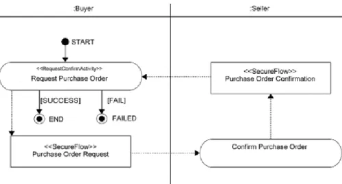
The first activity of such a diagram is stereotyped with a Business Transaction Type according to UMM ([UN/01] chapter 1, p.14 f.)). Figure 2 shows an example of such a diagram that fur- ther visualises business documents to be exchanged as object flows. Finally, the BOV specifies start and end states of a PIP execution and Business Process Activity Controls like Time to Perform for the overall PIP.
For each role of the BOV a component is defined in the FSV that is responsible for exchanging
Figure 2: UML activity diagram visualising the BOV of a PIP
business documents as Actions and control messages as Signals. The exchange of each message is detailed by Message Exchange Controls and finally the intended order of message exchanges is represented by an UML sequence diagram.
The main task of the IFV is the detailed specification of the business documents to exchange which is done in a xsd-file. Moreover the IFV specifies encryption details of the messages to be
5
http://www.ebxml.org/
exchanged.
Apart from defining a metamodel for PIPs, a major part of the RNIF is devoted to specifying
a reliable protocol for exchanging the messages of a PIP. This is different from the information
in the FSV where only the idealised flow of messages is given. RNIF defines four variants of
message exchange protocols as Business Message Patterns ([Ros02] p.75 ff) that can be used
to type a PIP.
8 3 AN APPROACH FOR MODELLING BUSINESS COLLABORATIONS
3 An approach for modelling business collaborations
As already pointed out in the introduction, automating business collaborations needs modelling support for communication purposes. Models provide this support by defining a unified system of concepts and sometimes even semantics for these concepts. Models are further useful for accomplishing analysis, design and documentation tasks. Subsection 3.1 introduces the two- step modelling approach referred to in the introduction. Subsections 3.2 and 3.3 show how UML activity diagrams and WSBPEL can be applied to modelling the CP and DP respectively.
3.1 The core approach
The idea for separating the CP and the DP of a business collaboration bases on the insight that collaboration participants first have to agree upon what to do in a collaboration from a global point of view before specifying a collaboration from a local point of view. A business collaboration can be interpreted as a single business process that spans multiple enterprises.
The purpose of the CP is to model this business process by identifying relevant states and actions. The purpose of the DP is to specify the distributed implementation of the overall business process.
3.1.1 The centralised perspective
The definition of state is crucial for modelling the CP on business collaborations. The goal of any business collaboration is achieving a new and common state, e.g. signing a new contract.
Moreover the applicability of transactions and the way transactions are conducted within a
collaboration may depend on what steps have been taken before. The exchange of an order
of goods may require a quote to be exchanged beforehand and refer to prices that are fixed in
the quote. Interpreting a collaboration as a single business process, we decided to model state
explicitly in our approach and to define it as the common view of the collaboration partners on
the progress of the collaboration (process state in the following). A process state is composed
of the relevant attributes of the collaboration, e.g. the information if a contract has already
been signed or if certain resources are free or not. Process states are therefore the basis for
communication between collaboration participants who negotiate which process states should
be reached and which attribute values should be associated with these process states. Clearly,
it is impossible in a truly distributed environment to ensure that the collaboration participants
have the very same view on process states at every point in time. So it is more adequate to
think of a process state as an abstract business state. The collaboration participants always
reside in the same business state or if any participant has changed its state then all other
participants must make a change to the same state in finite time and no further state changes
are allowed until all participants have reached that state. Such a semantics can be achieved
by using distributed consensus mechanisms. An alternative approach is to let the views of the
collaboration participants on progress diverge but then the number of process states to model
would possibly grow exponentially. That is why the use of so-called micro-choreographies
6is proposed to consistently change process states by means of two-phase-commit protocols (2PC in the following). If no communication is possible at all the use of so-called distributed time-outs is envisaged to make state changes, e.g. for releasing valuable resources of a participant. A distributed time-out is only allowed if communication was successful beforehand, e.g. it can be agreed upon the reservation time of a resource reservation while agreeing upon the reservation itself. The mechanism to negotiate a distributed time-out while performing a 2PC can be found in the following excursus.
Excursus: Distributed time-out after 2PC. This excursus presents the negotiation of a distributed time-out during the execution of a 2PC run. A distributed time-out can then be fired without any further communication.
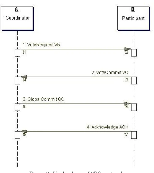
The discussion of this excursus concentrates on when the collaboration participants have to activate timers that fire the time-out events. Therefore, figure 3 shows an idealised run of 2PC. The labels used in figure 3 are used in the following discussion where labels tX represent points in time and labels VR, VC, GC and ACK represent the messages exchanged. The object instances A and B represent two participants of a 2PC run. To demonstrate the viability of negotiating a distributed time-out during a 2PC run, two scenarios are analysed:
• Scenario 1. In this scenario, B reserves resources in favour of A. B uses a distributed time-out to release these resources after a certain amount of time. But in any case, it should be provided that A can have faith in the reservation by B until A triggers a time- out event himself. Therefore B has to trigger a time-out event after A does. This can be accomplished by triggering the timer of A earlier than the timer of B.
The first step in doing so is that B reserves resources immediately before t3. If the 2PC run ends with a result of Abort afterwards, B releases the resources and no distributed time-out is needed at all. Otherwise, A activates its timer immediately before t5 whereas B activates its timer directly after t6. Let the duration of the timers be d. Then the time-out event of A is triggered at t5 + d at the latest and the time-out event of B is triggered at t6 + d at the earliest. As t5 necessarily precedes t6, the time-out event of A is triggered earlier than the time-out event of B if the clock drift of both is acceptable (see below). Hence, the goal is achieved.
Clearly, message losses must be taken into account. If VR and VC messages are lost, the emerging situations can easily be handled by aborting the 2PC run. If GC or ACK messages are lost, the situation is more complex.
The loss of such messages are detected by A by not receiving any ACK messages. In this case A repeatedly sends GC messages until he either receives an ACK message or a 2PC timer (not to confuse with the timer for distributed time-outs), activated by A before sending the first ACK message, has run out. In either case, A then proceeds in the business collaboration. Even if the 2PC timer mentioned runs out, A can have faith in the reservation of the resources because B reserved these before t3.
B detects the loss of GC or ACK messages by either never receiving a GC message or by receiving multiple GC messages. If B receives no GC messages at all in a certain time
6
The notion of micro-choreography is inspired by the fact that collaboration participants have to exchange
a set of messages according to some strict rules for implementing consistent changes of process states.
10 3 AN APPROACH FOR MODELLING BUSINESS COLLABORATIONS
Figure 3: Idealised run of 2PC protocol
period, manual intervention is needed to resolve the state of A. Duplicate GC messages can be answered by B with ACK messages but this is not necessary because A can proceed without ACK messages as well.
If ACK messages are lost A can only proceed after a 2PC timer has run out. In the meantime, B could already have need in performing further micro-choreographies. In order to avoid unnecessary delays in the execution of the collaboration, B can stop A from waiting for ACK messages by using piggy-backing. Therefore B adds an ACK message to the first message of the new micro-choreography. If A receives the message of the new micro-choreography it receives the missing ACK message as well and can terminate the 2PC run.
• Scenario 2. In this scenario A reserves resources for B. As this a symmetric case to scenario 1, the timer of B must be activated earlier than the timer of A.
In scenario 2, the reservation of resources is done by A immediately before t5. If the
reservation is not successful A aborts the 2PC run, otherwise Commit is the only possible
result of the 2PC run. B starts its timer immediately before t3 whereas A starts its timer
after successfully having reserved the resources. This means A starts its timer after t4.
Let d be the duration of the timers. Then, the time-out event of B is triggered at t3 + d at the latest whereas the time-out event of A is triggered at t4 + d at the earliest. As t3 necessarily precedes t4 the time-out event of B is fired earlier than the time-out event of A if the clock drift of A and B is acceptable (see below). Hence, the goal is achieved.
Clearly, the timer of B can only tentatively be activated and must be deactivated if the 2PC run terminates with a result of Abort. The tentative activation of the timer of B does not mean B can begin new micro-choreographies assuming that resources are re- served while the reservation by A fails later on. This situation to happen would require that B begins a new micro-choreography before the current 2PC run is terminated. To do so is not allowed.
The correctness of the mechanism for scenario 2 in the case of message losses can be con- firmed by looking at the properties of 2PC because 2PC already considers message losses.
If A and B detect an Abort result of the 2PC run, then either no timers for distributed time-out have been activated or the activation has been cancelled. No resources are then reserved either. If A detects a Commit result and B blocks continuously (because GC messages get lost), then B cannot use the resources reserved. But this is not a problem because the collaboration participants must ensure that message losses are not the stan- dard case. If A and B both detect a Commit result it only has to be considered that B must activate its timer before he sends the first (of possibly multiple) VC messages.
As the point in time at which the first VC message is sent precedes the point in time at which the first VC message is received, the time-out event of B is fired earlier as described above. Further cases do not exist.
It is noteworthy that the mechanism described here does not require the clocks of the partici- pants to be synchronised. This is because the activation of timers relies on time intervals and on the order of message dispatch and message receipt. A problem to be handled is clock drift, i.e.
the clock of A could run faster than the clock of B or the other way round. This problem can be solved by multiplying the timer duration of the participant who reserves resources for the other participant by a factor of λ. The value of λ can be deduced by looking at the maximum clock deviation of customary Real Time Clocks (RTC in the following). According to manufacturers of RTCs, the clock deviation ranges between 3 ppm approx. and 100 ppm approx. depending on the particular RTC product. To safely calculate λ, a clock deviation of 300 ppm approx.
is assumed. This means that a RTC runs 0.0003 * 3600 = 1.08 seconds per hour too fast or too slow as maximum. This means that the clock drift of A and B can be at most approx. 2 seconds per hour. Hence 1.0006 should be a safe value for λ. The collaboration participants have to ensure that the clock deviation assumed is not exceeded. Maybe time buffers have to be introduced for handling clock deviation excesses.
One could criticise that the proposed mechanism for realising distributed time-outs needs man- ual intervention in certain situations. But these situations are fairly rare assuming reasonable investment in communication infrastructure and 2PC is used here at the level of business processes. Manual intervention can therefore be justified.
end of excursus
Having defined process states and micro-choreographies as core concepts of the CP, the relation
of these concepts has to be clarified. A process state cannot be directly changed into another
process state. Either a global event, i.e. a distributed time-out, or a local event that triggers
12 3 AN APPROACH FOR MODELLING BUSINESS COLLABORATIONS a micro-choreography must be used to leave a process state. A distributed time-out must have been agreed upon before by means of distributed consensus and always points to exactly one other process state. Local events can be detected locally, but after detection of a local event the execution of a micro-choreography must be negotiated by means of a protocol because another participant might have detected a local event as well. The execution of a micro-choreography can lead to multiple process states depending on the content of the business messages that have to be exchanged during a micro-choreography. It is important to note that no data other than the content of the business messages that has been agreed upon by 2PC may be used to route between multiple process states. It is reasonable to divide the result of a micro-choreography in a technical result and a business result to perform the actual routing. The technical result is a boolean value that is true whenever all relevant business messages of a micro-choreography have successfully been exchanged, interpreted and agreed upon by 2PC. It is not sensible to represent a business result as either SUCCESS or FAILURE because it is not really clear if a cancellation of an order is a success or a failure nor is the set of possible business results always restricted to two values, e.g. in a case where an offer may be accepted, rejected or be decided upon at a later point in time. Finally, it is useful to introduce roles in the CP in order to prevent the modellers from specifying processes that are extraordinarily hard to implement.
Roles can be used to identify the 2PC coordinator of micro-choreographies, the participant in charge for detecting local events that trigger micro-choreographies as well as to make clear whose resources are released by means of distributed time-outs.
3.1.2 The distributed perspective
While the distributed environment of business collaborations can be largely ignored in the CP, the DP must respect the restrictions of distributed computing. As business collaborations usually cannot be built on a central technical infrastructure, automation based on the shared memory paradigm is hardly possible. Considering insecure communication media, e.g. commu- nication over the internet, the message passing paradigm is adequate for automating business collaborations. The following constraints must be addressed.
• There are no assumptions about how long a message travels from sender to receiver.
• Messages can overtake each other.
• Messages can be lost or be duplicated.
• Finally the clocks of the collaboration participants must be assumed to be not synchro- nised.
As already mentioned in the discussion of the CP, such an environment prevents the collabo-
ration participants from having exactly the same view on collaboration progress at every point
in time. But it can be made sure that any local process of a participant is at most one step
behind the local process of another participant by using the well-known 2PC. The detailed
protocols for specifying the implementation of the collaboration, in particular the implemen-
tation of micro-choreographies, depend to some extent on the application domain and on the
particular use case. This subsection therefore discusses the tasks for specifying the DP and gives detailed protocols only where appropriate. Generally speaking, the task of the DP is to represent the process states of a collaboration and to specify the number, types and order of messages to be exchanged. This task can be decomposed into the following packages.
Representing process states. Process states are abstract business states. Thus the current process state can be represented by a single variable of an enumeration type, that contains all possible process states. The attributes of a process state can then be deduced by relating the value of the variable to a process state in the CP.
Executing micro-choreographies. The messages to exchange within a micro-choreography (MC) depend on the state changes that should be performed. Arbitrary business documents can be exchanged within a MC. No matter what business documents are exchanged, at the end of a MC a 2PC run has to be performed in order to achieve distributed consensus whether all business documents have successfully been transmitted and interpreted or not. The coor- dinator of the 2PC run can be determined by choosing the participant who has received the last business document. Typically, all business messages then successfully have been exchanged and interpreted and the only task of the 2PC is to agree upon that. The result of such a 2PC run then always will be Commit, except communication failures prevent the participants from concluding such a result. In order to avoid blocking processes, manual intervention is needed in the typical 2PC blocking situation. The notification of such a blocking situation then must be performed reliably which can be safely done because the notification can be performed locally.
More detailed treatment can be found in literature (e.g. [TS02], section 7.5.1). Throughout this technical report the protocol for executing MCs will be called MC execution protocol.
Triggering the execution of micro-choreographies. A MC is usually triggered by the collaboration participant who sends the first message of the MC. In some process states there may be multiple MCs that can be triggered, maybe by different collaboration participants.
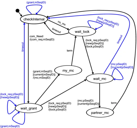
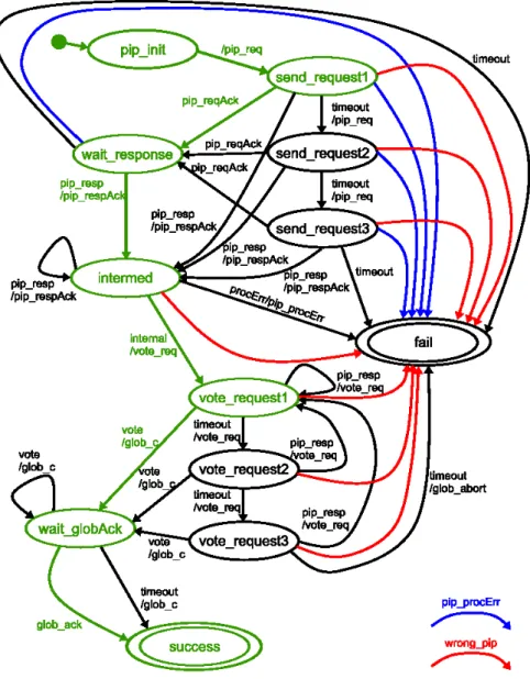
As the execution of a MC may lead to new process states where other MCs can be triggered the participant with the privilege to trigger a MC must be determined by a protocol. Such a protocol must also take into account that distributed time-outs can lead to process state changes and thus affect the applicability of MCs. Ideally, such a protocol negotiates an instance number for the execution of the MC as well. The so-called media control protocol (MCP) is introduced here to solve these tasks.
The discussion assumes two collaboration participants. In process states in which only one collaboration participant can trigger new MCs the MCP task is easy to solve. That is why only the case where both collaboration participants can trigger a MC is described. The protocol proposed can also be applied to the case where only one participant can trigger a MC. Model checking has been applied to develop the following protocol. The development and validation of the protocol is described in section 5.
Considering the constraints of the distributed environment (cf. p.12) the receiver of a message
can hardly be expected to really be ready to receive the message. The reason is that he might
have time-outed before. To be precise the main task of the MCP, i.e. determining who begins
14 3 AN APPROACH FOR MODELLING BUSINESS COLLABORATIONS the next MC, is redefined as following: At any point in time only one collaboration participant has the right to trigger a MC, i.e. to send the first message of the MC. If the other participant still waits for the first message to arrive, i.e. he does not time-out before, and if the message transmission does not take too long, then the MC can successfully be triggered by delivering the first message. Clearly, the first message of a former MC could be delivered as well but this message then has the wrong instance number. The MCP proposed here is not fair, i.e. one participant can continuously prevent the other from beginning MCs by acquiring the right to begin MCs himself. Only one participant of a MCP run can prevent the other from triggering MCs. A MCP run starts when a new process state is reached and it stops when a process state is left. In the following the privileged participant is called coordinator whereas the disadvantaged participant simply is called participant.
In order to acquire the right to trigger a MC the coordinator as well as the participant first have to request their communication right. If they are granted the right to trigger a MC and they didn’t change their MCP state in the meantime, then they can send the first message of the MC. Outdated messages of a MCP run are handled by means of sequence ids. To generate these ids the coordinator as well as the participant hold two sequence counters each. One counter counts the number of own requests and is incremented before any new request. The second counter contains the number of requests of the partner. The detailed usage is described below.
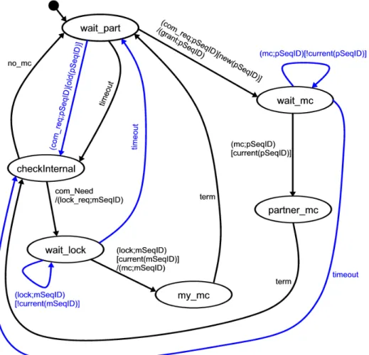
Figure 4 shows the protocol machine of the coordinator. The intended behaviour is displayed
in black colour. The states and transitions that are only introduced because of the constraints
of the distributed environment are displayed in blue colour. The coordinator starts the MCP
in state wait part. If he receives a communication request (com req ) in this state, he has to
check whether the sequence id contained in the request is bigger than the value of the counter
for the participant. If this is the case, the coordinator accepts the request for communication
and sends a grant message to the participant that contains the sequence id of the com req just
received. Afterwards the coordinator waits for the first message of a MC (mc ) that then must
use the sequence number of the grant message. If he receives such a message the MC begins and
the coordinator therefore switches to state partner mc. At this point the MC is executed. After
the MC has terminated the coordinator switches to state checkInternal and checks if he has to
trigger some MCs on his own. The coordinator also switches to state checkInternal if he time-
outs in state wait part. If there are no MCs to trigger in state checkInternal, the coordinator
switches to state wait part and waits for another com req sent by the participant. Otherwise
the coordinator increments the counter for his own requests and uses it as the sequence id of a
lock req message he sends to the participant in order to request communication himself. If the
coordinator then receives a lock message that carries a sequence id which has the same value
as the sequence id he used in his last lock req, the coordinator switches to state my mc and
then sends the first message of the MC adding the value of his request counter as sequence
id. After the MC has terminated the coordinator switches to state wait part and checks for
new com reqs to arrive. All other transitions are used to handle communication errors. To
do so, outdated messages are deleted or states are left by means of time-out because some
expected messages do not arrive. Figure 5 shows the protocol machine of the participant. The
participant starts a MCP run in state checkInternal. If he doesn’t need to execute any MCs, the
participant switches to state wait lock and waits there for lock req messages of the coordinator
to arrive. The participant checks if an arriving lock req message carries a sequence id that is
bigger than his partner counter. If this is the case, the participant updates his partner counter
with the value of the sequence id and sends back a lock message carrying the same value. If no
Figure 4: Coordinator automaton of MCP
lock req message arrives in state wait lock the participant time-outs and then switches to state checkInternal to check the need for own MCs again.
If the participant has received a valid lock req in state wait lock he switches to state wait mc.
There, the participant waits for the first message of the negotiated MC (mc) to arrive that must
carry a sequence id that is the same as his partner counter. If such a mc message arrives the
participant switches to state partner mc and then performs the rest of the MC. After the MC
has terminated, the participant switches to state checkInternal again to check the need for own
MCs. If any MCs ought to be executed the participant increments his request counter and then
uses its value as a sequence id of a com req message he sends to the coordinator. Afterwards
the participant switches to state wait grant. If a grant message arrives with a sequence id
that is the same as the participant’s request counter, the participant switches to state my mc
and performs the MC. After the termination of the MC the participant reaches state wait lock
again and waits for lock req messages. In state wait grant the participant can receive a lock req
instead of a grant as well. If such a lock req message contains a valid sequence id the participant
must send back a matching lock message analogously to state wait lock and then switch to state
wait mc. This behaviour resolves the conflict that emerges from both partners trying to acquire
the right to trigger a MC. All other transitions and states are used to handle communication
errors analogously to the coordinator protocol machine.
16 3 AN APPROACH FOR MODELLING BUSINESS COLLABORATIONS
Figure 5: Participant automaton of MCP
The MCP described so far only ensures that at any point in time at most one communication partner has the right to trigger a MC, i.e. at most one partner is in the state labelled my mc.
The second partner would need a permission to enter the same state. But as the first partner does not handle any requests before the MC has finished (then state my mc is left), the second partner cannot gain such a permission.
It has not yet been described in detail how the instance numbers are provided for the execution of MCs. The communication partners can choose the sequence id of the request message they used to acquire the right to trigger a MC as an instance number of the MC. These sequence ids can easily be made unique by using a scheme like the following. The coordinator starts his sequence id counter (request counter) with a value of 1 whereas the participant starts with 0.
Both partners then always increment their counters by 2.
Distributed time-outs (which lead to new process states) can be handled by checking if the
respective timer has run out in a MCP state that is reached again and again. The start states
of the communication partners can be used for this task, i.e. wait part for the coordinator and
checkInternal for the participant. If a distributed time-out event is detected, the current MCP
run is terminated, the new process state (not a new MCP state) is entered and a new MCP
run is started. As the clocks of the communication partners cannot be assumed to be tightly synchronised and as the transmission time of messages that are used to negotiate a distributed time-out beforehand must be considered, a distributed time-out can lead to an intermediate state. The communication partners then reside in different process states until the second partner has detected the distributed time-out as well. There could be MCs that are applicable for a communication partner in both of these process states. Then a MC could be started with the communication partners assuming different process states which could lead to diverging local views on the collaboration progress. This clearly is unintended. To avoid diverging views the current process state can be added to lock req and com req messages. If the process state contained in such a message does not correspond to the local process state when evaluating such a message, no answer is sent back. The communication partner who has not performed the distributed time-out will then eventually detect and perform it.
The description how MCs are integrated in the MCP deviates from reality for demonstration and analysis purposes. The first message of a MC is not transmitted by the MCP as presented in the protocol machines but by the MC itself. The transmission of the first MC messages is added to the MCP because otherwise it would not be so apparent when MCs are performed.
Further, the outgoing transitions from my mc and partner mc are simplifying reality. Any MC includes a 2PC run at the end. So, the communication partners could be blocked
7while performing the MC. Then the non-blocking partner could not acquire the right to trigger MCs because his partner wouldn’t answer. This problem can be solved by piggybacking the result of the last 2PC run to any new lock req or com req message. The blocking partner would then first read the 2PC result, then switch MCP state and finally evaluate the new request message.
Finally process state changes that emerge from MC runs must be considered. If the result of a successful MC run leads to a process state change the respective partner would terminate the current MCP run, switch the process state and eventually start a new MCP run. If the other partner blocked during the MC run the partners would then reside in different process states. As opposed to the situation that emerges from distributed time-outs, in this situation, progress can only be achieved by freeing the blocking partner. But this definitely would lead to a process state change of the blocking partner as well.
Generating and interpreting business documents. When automating existing business collaborations, the business logic for generating and interpreting business documents is implic- itly, i.e. in the heads of business people, or explicitly, i.e. in business software, present. Further this logic depends on each particular use case. That is why these tasks are not described in detail in this technical report. Instead, the assumption is made that the evaluation of any business document can be represented by a finite set of values. It is also noteworthy that the generation and interpretation of business documents is a lever for applying local business pol- itics to the collaboration. In this technical report the so-called internal process is responsible for generating and interpreting business documents.
7
At most one partner can be blocked because of 2PC properties
18 3 AN APPROACH FOR MODELLING BUSINESS COLLABORATIONS Detecting events of the real world and changing the real world. Business collabora- tions are driven by changes in the real world (events) and affect the real world. It is assumed that there are already systems that are able to detect events and change the state of the real world when automating business collaborations. Nevertheless, there must be a clear concept on how to relate these existing systems to the CP and DP on the collaboration. Details depend on particular use cases. Thus this report does not provide general integration rules but shows how such existing systems can be integrated in the use case analysed in section 4. Again, it is noteworthy that integration of such systems is a lever for applying local business politics to the collaboration. In this technical report the so-called internal process is responsible for detecting events of the real world and for changing the real world.
Specifying the control flow of the collaboration. Control flow is needed to route between process states and MCs. The choice of the MCs to execute depends on events from the real world. The choice of new process states depends on distributed time-outs and the results of MC runs. Further constructs like decision, loop, parallel flow or synchronization are needed to fine-tune the control flow. In this technical report the so-called local process is responsible for the control flow of the collaboration. This local process, augmented by the MCP and MC execution protocol will be called the protocol process in this report.
To complete this subsection, an assumption implicitly contained in the approach proposed here is pointed out. Before any changes to the real world can be made a 2PC run has to be successfully executed at the end of a MC run. A 2PC run to complete successfully requires that every business document of a MC has to be successfully exchanged and interpreted. From this follows that the business documents must be interpreted again (after the 2PC run) to perform the changes to the real world. The application of 2PC would be useless if business documents would not be available or could not be interpreted after the 2PC run. Therefore the assumption must be made that a business document exchanged during a MC is stored safely and that once a business document was interpreted successfully, it can be interpreted successfully again and again.
3.2 Using UML activity diagrams for modelling the centralised per- spective
To efficiently use the concepts introduced, an appropriate modelling language has to be pro- vided. We found that UML 1.5 activity diagrams are a good choice for the following reasons.
UML 1.5 activity diagrams ([OMG03]) are a language suitable for modelling business processes as stated in [DH01]. Activity diagrams are a visual language thus supporting the commu- nication task of a model. There’s a large user community using activity diagrams so that a modelling approach based on activity diagrams can easily be adopted in practice. UML is a standardised language which provides the evolution and free-of-charge use of the language and a more or less common meaning of the modelling elements simplifying the exchange of models.
Finally, the artefacts of our modelling approach can easily be mapped to activity diagram el-
ements as described below. This proposal for modelling the behavioural view on the CP with
UML 1.5 activity diagrams can easily be modified to be used with UML 2.0 statecharts.
Process states can be represented by state machine states as activity diagrams are a special case of state machines in UML 1.5. Such states can be hierarchically composed. Thus all attributes that make up the process state of a collaboration can conveniently be modelled as substates of the state machine state. Any micro-choreography or distributed time-out that can be applied in a certain process state is connected to that process state by a transition.
Micro-choreographies can be modelled as activities where a single activity models a whole MC. Note that the way distributed consensus is achieved within the activity is not explicitly shown. A consistent outcome of the MC is only implicitly required. The point in time at which MCs get triggered can be captured by events that are added to the transitions that lead into an activity. Such events are always local to one participant. The name of the participant who detects the event can be added to the event identifier in order to make clear that he is responsible for detecting it. Further, guards of incoming transitions to an activity can be used to condition the triggering of the MC. Variables in such guards can be local to one participant as this participant can decide upon the triggering of a MC without consulting his collaboration partners. Activities terminate when the distributed commit protocol that has to be executed at the end of each MC has finished. Therefore no events are allowed in outgoing transitions of an activity. The result of a MC can be visualised as an object flow with multiple result types.
The result of a MC execution can then be used in guards to route the collaboration.
Distributed time-outs can be represented as UML when or after events of transitions. Dis- tributed time-outs are designed for situations where no communication is possible, so these transitions directly connect two process states. While distributed time-outs are detected in process states, their corresponding timers are activated in MCs. This leads to unclear seman- tics that may vary from use case to use case. The following questions therefore have to be answered. If there are multiple transitions that lead into a process state and are preceded by a MC, which of these transitions activate timers for a distributed time-out? If there are multiple distributed time-outs in a process state, must all or only a part of them be activated by a MC?
If there are loops in the collaboration, is the timer of a distributed time-out triggered each time a MC leads to a process state or only the first time?
The possibility of loops in a collaboration gives rise to another semantics question. If a process state is left before the timer of a distributed time-out event is detected, should the correspond- ing timer then continue to progress, should it halt until the process state is reached again or should it be completely cancelled?
Two hints can be given for answers to this questions without looking at use cases. If the execu- tion of a MC results in technical failure no timers of distributed time-outs may be affected at all because in extreme cases a participant may not even have noticed that his partner has tried to execute a MC. And, if timers are not completely cancelled when leaving a process state, then the distributed time-out events they fire can only be applied if the collaboration resides in the corresponding process state or at the moment this process state is reached again.
Control flow is supported by activity diagrams with various node types. Alternative flows of
execution can be visualised by decision and merge nodes whereas parallel flows of execution can
be visualised by fork and join nodes. Further, transitions can be used to specify the relation
between process states and micro-choreographies. Process states may have multiple incoming
and outgoing transitions. Outgoing transitions of a process state always have an event that
shows which real world event leads to the execution of the transition, i.e. local events of the
20 3 AN APPROACH FOR MODELLING BUSINESS COLLABORATIONS participants that trigger MCs or global distributed time-out events. Transitions accompanied by local events end in activities whereas transitions accompanied by global events end in new process states.
Micro-choreographies always have exactly one incoming and one outgoing transition. Such an outgoing transition ends in a decision process that determines the next process state depending on the outcome of the micro-choreography. Therefore, the outcome is divided into a technical and a business result. If the execution of a MC fails technically the process always returns to the process state from which the MC was initiated. This case can be represented as a guard with the constant technical failure (TF). If the execution of a MC succeeds technically, the next process state depends on the content of the business documents that have been exchanged. This circumstance can be represented by using the names of the relevant business documents as the initial part of variable names that are evaluated in guards to determine the next process state.
The restriction that there may only be one incoming transition to a micro-choreography is made to guarantee an unique process state to fall back to in case of a TF. Hence, the same MC may be modelled multiple times within a collaboration.
Guards can be used as described in the discussion of process states and MCs. Finally transitions may be accompanied by actions. Actions are useful for manipulating local variables of the participants for routing purposes. Note that actions may not be used to manipulate process states because distributed consensus would therefore be needed.
Roles are a means to specify the tasks a collaboration participant is obliged to fulfil and are useful for the purposes described in section 3.1.1. In activity diagram modelling, swimlanes can be used to visualise roles. Further, role names can be used as part of event identifiers to meet the tasks described in section 3.1.1.
Business documents store the information that is negotiated during a collaboration. In activity diagram modelling, object flows can be used to reference the structural definition of such documents thus abstracting from the details of such documents.
3.3 Using WSBPEL for modelling the distributed perspective
While a modelling language for the CP must support the communication task of models, it is the primary task of a modelling language for the DP to provide a concise model that can easily be executed. WSBPEL is such a language that describes a business collaboration at the level of Web Service calls. WSBPEL models can be executed by deploying them on adequate process engines providing the right binding information. WSBPEL is well-suited for modelling the DP of business collaborations for various reasons. The modeller can take the point of view of one collaboration participant interacting with his partners of the collaboration via message exchanges which is precisely the task of modelling the DP. Web Services are platform and programming language independent thus supporting the integration of heterogeneous systems which are likely to be found when integrating business processes. And, as well as activity diagrams, WSBPEL has a large user community and is a standardised language.
The main tasks in modelling the DP have already been identified in subsection 3.1.2. The
task of representing process states can be fulfilled by using a single global variable with an
enumeration type that enumerates all possible process states. XML Schema
8can be used to create such an enumeration type. The task of specifying the control flow of the collaboration can then be accomplished by referencing that global process state variable. The whole business collaboration from a single participant’s point of view can be represented in WSBPEL as a WSBPEL while loop waiting for termination of the collaboration. Within this loop a WSBPEL switch construct can be used to select the right code depending on the content of the global process state variable. The condition for terminating the collaboration is then manipulated in process state logic. The WSBPEL scope construct can be used to support the specification of the process state logic of a particular process state. A WSBPEL scope can be used to restrict the validity of variables to a particular code fragment and it offers the WSBPEL onAlarm construct for specifying relative and absolute timers, i.e. timers with a time period or with a fixed point in time. These timers can be used to model distributed time-outs by writing appropriate variables when running out. Therefore, it has to be considered that the timer of a distributed time-out is activated during the execution of a MC that has been triggered in a different process state. Thus it makes no sense to use relative timers because a collaboration participant could be blocked during the 2PC run of the MC while his partner is already able to proceed. As relative timers are activated when the WSBPEL scope of a process state gets activated, there would be no control over the sequence of starting timers. Absolute timers that refer to global datetime variables should be used instead. Then an absolute point in time can be computed for this timer when performing the 2PC run of the respective MC. When such a timer runs out a variable can be written to store the information that a distributed time-out event has been fired. Unfortunately, there’s a drawback of this approach. A 2PC run could block that long that the point in time the timer runs out already has passed when the WSBPEL scope of the new process state is reached. The WSBPEL standard does not define whether a time-out event should be fired or not in such a situation which may lead to compatibility problems among WSBPEL engines. Therefore the assumption is made that a process state is entered before a respective timer of a distributed time-out, if any, has run out. The fact, that the duration of a reservation at the level of business processes is long relative to the time needed to perform a 2PC run and resolving blocking situations, justifies this assumption. Special scenarios that do not meet this assumption need different approaches.
The task of triggering the execution of micro-choreographies is addressed by using the MCP (p. 13). As already stated above a new MCP run is started each time a new process state is reached. To represent the MCP in WSBPEL, a loop can be used that is inserted directly within the WSBPEL scope of a process state. Within this loop different code fragments can be applied depending on the current process state. MCP states can be represented by a variable with an enumeration type that enumerates all MCP states. An example of different code fragments depending on process states is the choice between the coordinator and the participant role of the MCP. In order to detect distributed time-outs, the variables storing the information about distributed time-out events can be read before switching over the MCP states in the MCP loop.
Clearly, a distributed time-out can then only be detected when a MCP state changes. A MCP state change can be deferred if a 2PC run blocks. But then a MC run is just being performed and distributed time-outs shall not be applied during a MC run.
Finally a WSBPEL model of the DP must also address the tasks of detecting events of the real world and changing the real world, generating and interpreting business documents as well as
8